ACI Farfisa myCom 1MCFCPL Manuale del proprietario
- Tipo
- Manuale del proprietario

- 1 -
123
456
789
0BA
Mi 2470
Kit 1MCFCPL
PRS210
Trasformatore
Transformer
PL92
Tettuccio antipioggia e telai portamoduli
Rain shelter with module frames
PL11G
Posto esterno citofonico con tecnologia GSM
GSM intercom door station
FC52PL
Tastiera per controllo accessi
Keypad for access control
IT
KIT CITOFONICO GSM CON TASTIERA PER
CONTROLLO ACCESSI
EN
GSM INTERCOM KIT WITH KEYPAD FOR AC-
CESS CONTROL
123
456
789
0BA
Installazione
Installation
1
2
Posizionare l'antenna tra il riporto del telaio ed
il modulo posto esterno.
Insert the antenna between the top plastic
frame and the GSM module.
3
4
- 4 -
PL11G
220-230V
0
127V
PRS210
FC52PL
1 2 3
4 5 6
7 8 9
0 BA
PL92
PL11G
FC52PL
IN1
IN2
GND
X
NA1
C1
/+
/-
12Vac
NC1
NO1
C1
NC1
PA
*
CA
*
SE
*
TA
*
NC2
NA2
C2
NC2
NO2
C2
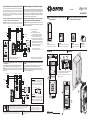
Schémas d’une installation de portier GSM
Les 2 schémas suivants permettent l’activation du portail automatique et
de la serrure électrique soit en composant le code programmé sur le
clavier FC52PL, soit en utilisant la fonction CLIP du poste extérieur
PL11G, soit en composant sur le téléphone le numéro à 2 chiffres de
activation pendant la conversation avec le poste extérieure ( voir les
instructions jointes aux produits).
1) Schéma avec actionnement en parallèle des relais 1 et 2 du
clavier FC52PL avec les relais 1 et 2 du poste extérieur PL11G.
Attention. Avec ce schéma les relais 1 et 2 du clavier FC52PL et du poste
extérieur PL11G doivent être programmés tous de la même façon.
127V0 230V
110-127Vac
220-230Vac
127V0 230V
PRS210
CA. Portail automatique.
Portal automático
PA. Poussoir ouvre porte (optionnel).
Pulsador abrepuerta (opcional).
SE. Gâche électrique (12Vca-1A max.).
Cerradura eléctrica (12Vca-1A max).
TA. Transformateur additionnel de 12Vca et
de puissance adéquate pour l’activation
de la serrure électrique (type PRS210)
Transformador adicional de 12 Vca y
de potencia adecuada por la activacion
de la cerradura electrica (tipo PRS210).
* Articles non inclus dans le kit.
Artículos no incluidos en el kit.
2) Schéma avec actionnement direct des relais 1 et 2 du poste
extérieur PL11G.
Les relais du clavier FC52PL ne commandent pas directement les
serrures, mais elles sont activées en utilisant les entrées du poste
extérieur PL11G.
Attention. Avec ce schéma il faut programmer correctement les modes
et les temps d’activation des entrées et des sorties du poste extérieur
PL11G.
Entrées
Entradas
2) Esquema con accionamiento directo de los relés 1 y 2 del puesto
exterior PL11G.
Los relés del teclado FC52PL no mandan directamente las cerraduras,
pero ellas son activadas utilizando las entradas del puesto exterior
PL11G.
Atención. Con este esquema hace falta programar correctamente los
modos y los tiempos de activación de las entradas y las salidas del
puesto exterior PL11G.
Esquemas de una instalación de portero GSM
Los 2 esquemas siguientes permiten la activación del portal automático
y de la cerradura eléctrica sea componiendo anteriormente el código
programado sobre el teclado FC52PL, sea utilizando la función CLIP
del puesto exterior PL11G, sea componiendo sobre el teléfono el
número a 2 cifras de activación durante la conversación con el puesto
externo ( ver las instrucciones adjuntas a los productos).
1) Esquema con accionamiento en paralelo de los relés 1 y 2 del
teclado FC52PL con los relés 1 y 2 del puesto exterior PL11G.
Atención. Con este esquema los relés 1 y 2 del teclado FC52PL y del
puesto exterior PL11G tienen que ser programados todo de la misma
manera.
- Los conductores en negrita deben tener una
sección mínima de 0,75 mm² (AWG 18).
- Les conducteurs marqués en foncé ont une
section minimum de 0,75mm² (AWG18).
IMPORTANT
Afin de réduire le bruit dû à la commutation de
la serrure électrique, il est nécessaire de relier
le transil (inclus dans l'article FC52PL) aussi
près que possible de la charge.
IMPORTANTE
Con el fin de reducir el ruido debido a la
conmutación de la cerradura eléctrica, es
necesario conectar el tránsil (incluido en el
artículo FC52PL) lo más cerca posible a la
carga.
PL11G
220-230V
0
127V
PRS210
FC52PL
1 2 3
4 5 6
7 8 9
0 BA
PL92
PL11G
FC52PL
NA1
C1
/+
/-
NC1
NC2
NO1
NO2
C1
C2
NC1
IN1
IN2
GND
X
NC2
NA2
C2
CA
*
PA
*
PA
*
SE
*
12Vac
TA
*
ACI srl Farfisa Intercoms
Via E. Vanoni, 3 • 60027 Osimo (AN) • Italy
Tel: +39 071 7202038 (r.a.) • Fax: +39 071 7202037
e-mail: [email protected] • www.acifarfisa.it
Smaltire il dispositivo secondo quanto prescritto dalle norme per la tutela dell'ambiente.
Dispose of the device in accordance with environmental regulations.
Écouler le dispositif selon tout ce qu'a été prescrit par les règles pour la tutelle du milieu.
Eliminar el aparato según cuánto prescrito por las normas por la tutela del entorno.
Disponha do dispositivo conforme regulamentos ambientais.
Werden Sie das Gerät in Übereinstimmung mit Umweltregulierungen los.
La ACI Srl Farfisa Intercoms si riserva il diritto di modificare in qualsiasi momento i prodotti qui illustrati.
ACI Srl Farfisa Intercoms reserves the right to modify the products illustrated at any time.
La ACI Srl Farfisa Intercoms se réserve le droit de modifier à tous moments les produits illustrés.
Cod. 52705050
ACI Srl Farfisa intercoms se reserva el derecho de modificar en cualquier momento los productos ilustrados aquí.
E’ reservada a ACI Srl Farfisa intercoms o direito de modificar a qualquer momento os produtos aqui ilustrados.
Änderungen vorbehalten.
SE
*
transil

- 2 -
PL11G
220-230V
0
127V
PRS210
FC52PL
1 2 3
4 5 6
7 8 9
0 BA
PL92
PL11G
FC52PL
IN1
IN2
GND
X
NA1
C1
/+
/-
12Vac
NC1
NO1
C1
NC1
PA
*
CA
*
SE
*
TA
*
NC2
NA2
C2
NC2
NO2
C2
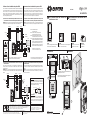
Schemi installativi di un impianto citofonico GSM
I 2 schemi seguenti permettono l'attivazione del cancello automatico e
della serratura elettrica sia componendo il codice precedentemente
programmato sulla tastiera FC52PL, sia utilizzando la funzione CLIP del
posto esterno PL11G, sia componendo sul telefono il numero a 2 cifre di
attivazione durante la conversazione con il posto esterno (vedere le
istruzioni allegate ai prodotti).
1) Schema con azionamento in parallelo dei relè 1 e 2 della tastiera
FC52PL con i relé 1 e 2 del posto esterno PL11G.
Attenzione. Con questo schema i relè 1 e 2 della tastiera FC52PL e del
posto esterno PL11G devono essere programmati tutti allo stesso modo.
127V0 230V
110-127Vac
220-230Vac
127V0 230V
PRS210
CA. Cancello automatico.
Automatic gate.
PA. Pulsante apriporta (opzionale).
Door release push-button (optional).
SE. Serratura elettrica (12Vca-1A max.).
Electric door lock (12Vac-1A max).
TA. Trasformatore aggiuntivo da 12Vca e di
potenza adeguata per l'azionamento
della serratura elettrica (tipo PRS210).
Additional transformer from 12Vac and
appropriate power to activate the elec-
tric door lock (type PRS210).
* Articoli non presenti nel kit.
Articles not included in the kit.
2) Schema con azionamento diretto dei relè 1 e 2 del posto
esterno PL11G.
I relè della tastiera FC52PL non comandano direttamente le serrature, ma
esse sono attivate utilizzando gli ingressi del posto esterno PL11G.
Attenzione. Con questo schema occorre programmare correttamente i
modi ed i tempi di attivazione degli ingressi e delle uscite del posto
esterno PL11G.
Ingressi
Inputs
2) Diagram for direct operation of relays 1 and 2 of the door station
PL11G.
Relays of keypad FC52PL do not drive directly the lock releases, but
them are activated through the inputs of door station PL11G.
Attention. The previous diagram requires that operating modes and
activation times of either inputs or outputs of door station PL11G had
been all opportunely programmed.
Installation diagram for a GSM intercom system
The two following diagrams show how to operate an automatic gate and
an electrical lock release either entering a personal code on the Keypad
FC52PL, or through the CLIP function of GSM module PL11G, or
dialling, on your telephone, the 2 digit codes for the actuation of the two
output relays during a conversation with the door station (for details see
the enclosed technical manual of the products).
1) Diagram for parallel operations of relay 1 and 2 of keypad
FC52PL with relays 1 and 2 of the door station PL11G.
Attention. The previous diagram requires that relays 1 and 2 of keypad
FC52PL and those of the door station PL11G had been all programmed
with the same operating mode.
-
The cables, which are heavily outlined, have
a minimum section of 0.75mm² (AWG18).
- I conduttori in neretto devono avere una sezio-
ne minima di 0,75mm² (AWG18).
IMPORTANTE
Al fine di ridurre i disturbi dovuti alla
commutazione della serratura elettrica, è ne-
cessario collegare i transil (inclusi nell'artico-
lo FC52PL) il più vicino possibile al carico.
IMPORTANT
In order to reduce the noise due to the
switching of the electric lock, it is necessary
to connect the transil (included in the article
FC52PL) as close as possible to the load.
PL11G
220-230V
0
127V
PRS210
FC52PL
1 2 3
4 5 6
7 8 9
0 BA
PL92
PL11G
FC52PL
NA1
C1
/+
/-
NC1
NC2
NO1
NO2
C1
C2
NC1
IN1
IN2
GND
X
NC2
NA2
C2
CA *
PA *
PA *
SE *
12Vac
TA
*
ACI srl Farfisa Intercoms
Via E. Vanoni, 3 • 60027 Osimo (AN) • Italy
Tel: +39 071 7202038 (r.a.) • Fax: +39 071 7202037
e-mail: [email protected] • www.acifarfisa.it
Smaltire il dispositivo secondo quanto prescritto dalle norme per la tutela dell'ambiente.
Dispose of the device in accordance with environmental regulations.
Écouler le dispositif selon tout ce qu'a été prescrit par les règles pour la tutelle du milieu.
Eliminar el aparato según cuánto prescrito por las normas por la tutela del entorno.
Disponha do dispositivo conforme regulamentos ambientais.
Werden Sie das Gerät in Übereinstimmung mit Umweltregulierungen los.
La ACI Srl Farfisa Intercoms si riserva il diritto di modificare in qualsiasi momento i prodotti qui illustrati.
ACI Srl Farfisa Intercoms reserves the right to modify the products illustrated at any time.
La ACI Srl Farfisa Intercoms se réserve le droit de modifier à tous moments les produits illustrés.
Cod. 52705050
ACI Srl Farfisa intercoms se reserva el derecho de modificar en cualquier momento los productos ilustrados aquí.
E’ reservada a ACI Srl Farfisa intercoms o direito de modificar a qualquer momento os produtos aqui ilustrados.
Änderungen vorbehalten.
SE
*
transil
- 3 -
123
456
789
0BA
Mi 2470
Kit 1MCFCPL
PRS210
Transformateur
Transformador
PL92
Visière antipluie avec cadres
Caja de superficie con soportes
PL11G
Plaque de rue avec technologie GSM
Placa de calle con tecnología GSM
FC52PL
Clavier pour contrôle d'accès
Teclado por el control de los ac-
cesos
FR
KIT DE PORTIER AVEC CLAVIER POUR CON-
TRÔLE D'ACCÈS
ES
KIT DE PORTERO CON TECLADO POR EL
CONTROL DE LOS ACCESOS
Installation
Instalación
1
2
Positionner l’antenne entre le report du cadre
port modules et le module mis extérieur.
Colocar la antena entre el marco y el módulo
del puesto exterior.
3
4
123
456
789
0BA
-
 1
1
-
 2
2


ACI Farfisa myCom 1MCFCPL Manuale del proprietario
- Tipo
- Manuale del proprietario
in altre lingue
Documenti correlati
-
ACI Farfisa 1AEXD Manuale del proprietario
-
-
-
-
-
-
-
-
-