
PASS
(600-800-1200-1800-2500
800/24VDC)
Motoriduttori elettromeccanici
ISTRUZIONI PER L’INSTALLAZIONE
Irreversible electromechanical
INSTRUCTIONS FOR INSTALLATIONS
P DNL D
I IUK F E
PASS
La pagina si sta caricando...

3
I
F
E
P
UK
NL
D
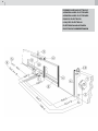
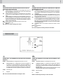
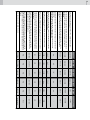
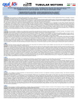
Motoriduttore cavo a 4 conduttori da 1,5 mm²
PASS 800/24Vdc alimentazione cavo a 2 conduttori da 1,5 mm² per distanze max.
3 m dall’apparecchiatura; per distanze maggiori cavo da 2,5 mm² (max. 6 m)
Fotocellula a raggi infrarossi modulati; 2 coppie, 1 interna ed 1 esterna.
Antenna del radioricevitore.
Costa pneumatica.
Pulsantiera.
Cremagliera.
Selettore a chiave.
Cavo coassiale schermato.
Linea di alimentazione all’apparecchiatura (attenersi alle Norme vigenti;
per l’Italia 46/90).
Segnalatore a luce lampeggiante a 220 V.
ATTENZIONE: è importante che sulla linea di alimentazione venga installato,
a monte dell’apparecchiatura, un interruttore magnetotermico onnipolare con
apertura minima dei contatti pari a 3 mm.
1
2
3
4
5
6
7
8
9
10
Motorredutor Cabo com 4 condutores de 1,5 mm²
PASS 800/24Vdc Cabo de alimentaҫão com 2 condutores de 1,5 mm² para
distâncias maiores, cabo de 2,5 mm² (max. 6 m).
Fotocélula de raios infravermelhos modulados: 2 pares, 1 interno e 1 exter-
no.
Antena do receptor.
Costa pneumática.
Botoneira.
Cremalheira.
Selector de chave.
Cabo coaxial blindado.
Linha de alimentação da aparelhagem (seguir as Normas em vigor).
Lâmpada pisca-pisca de 220 V.
ATENÇÃO: É importante que na linha de alimentação seja montado, a mon-
tante da aparelhagem, um interruptor magnetotérmico omnipolar com abertura
mínima dos contactos de 3 mm.
1
2
3
4
5
6
7
8
9
10
Motorreductor Voedingskabel met 4 geleiders van 1,5 mm²
PASS 800/24Vdc Voedingskabel met 2 geleiders van 1,5 mm² voor een max.
afstand van 3 meter van de apparatuur; voor langere afstanden, kabel van 2,5
mm² (max. 6 meter).
2 paar fotocellen: één aan de binnenzijde, één aan de buitenzijde
Antenne
Veiligheidsstrip
Drukknoppaneel
Tandlat
Sleutelcontact
Coaxkabel
Voedingsspanning 220-230 V, 50-60 Hz. (respecteer de van kracht zijnde
normen)
Knipperlicht 220 V
OPGELET: Het is heel belangrijk dat er een onderbrekingsschakelaar wordt
geplaatst op alle voedingsdraden. De minimum opening van deze schakel-
contacten moet 3 mm. bedragen.
1
2
3
4
5
6
7
8
9
10
Gearmotor cable with 4 conductors of 1,5 mm²
PASS 800/24Vdc Power supply cable with 2 conductors of 1,5 mm² for di-
stances max. 3 m from the control unit; for bigger distances cable of 2,5 mm²
(max. 6m)
Two pairs of modulated infrared photocels: one internal and one external.
Antenna.
Pneumatic strip.
Push-button panel.
Rack.
Key-selector.
Screened coaxial cable.
Power supply line to equipment (follow regulations in force).
220-230 V ashing light.
WARNING: It is important that an omnipolar magneto-thermal switch with
a contact opening of minimum 3 mm is installed on the power supply line,
upstream of the equipment.
1
2
3
4
5
6
7
8
9
10
Motoréducteur câble à 4 conducteurs de 1,5 mm²
PASS 800/24Vdc Alimentation par câble à 2 conducteurs de 1,5 mm² pour
distances max. 3 m de la platine de commande; pour distances supérieures
câble de 2,5 mm² (max. 6 m).
Photocellule à rayon infrarouges modulés; 2 paires (1 interne, 1 externe).
Antenne de réception.
Seuil pneumatique.
Tableau de commande.
Crémaillère.
Sélecteur à clé.
Câble coaxial blindé.
Ligne d’alimentation de la platine (respecter les normes en
vigueur).
Clignotant à 220 V.
ATTENTION: Sur la ligne d’alimentation, en amont de la platine, il est important
de monter un interrupteur magnétothermique omnipolaire ayant une ouverture
des contacts minimale de 3 mm.
Getriebemotor vier-adriges Kabel von 1,5 mm²
PASS 800/24Vdc Stromversonrgung über Zweileiterkabel mit 1,5 mm² für
Entfernungen bis max. 3 m vom Gerät; für größere Entfernungen Kabel mit
2,5 mm² (bis max. 6 m)
Lichtschranke mit modulierten Infrarotstrahlen; 2 Paar, 1 innen und 1 außen.
Antenne des Funkempfängers.
Pneumatische Schiene.
Druckknopftafel.
Zahnstange.
Schlüsselwahlschalter.
Abgeschirmtes Koaxialkabel.
Gerätzuleitung (die geltenden Vorschriften befolgen; in Italien 46/90).
Blinklicht 220 V.
ACHTUNG: Es ist wichtig, daß an der Zuleitung stromauf des Geräts ein
thermomagnetischer, allpoliger Schalter mit 3 mm Kontaktmindestöffnung
angebracht wird.
1
2
3
4
5
6
7
8
9
10
Motorreductor cable de 4 conductores de 1,5mm²
PASS 800/24Vdc Alimentación por cable de 2 conductores de 1,5 mm² para
distancias max. 3 m del equipo de mando; para distancias superiores cable
de 2,5 mm² (max. 6 m)
Fotocélula de rayos infrarrojos modulados; dos pares, uno interior y otro
exterior.
Antena.
Banda pneumática.
Botonera.
Cremallera.
Selector de llave.
Cable coaxil blindado.
Línea de alimentación al equipo (atenerse a las normas vigentes).
Destellador a 220 V.
ATENCIÓN: es importante instalar en la línea de alimentación, antes del
equipo, un interruptor magnetotérmico omnipolar con abertura mínima de los
contactos igual a 3 mm.
1
2
3
4
5
6
7
8
9
10
1
2
3
4
5
6
7
8
9
10
La pagina si sta caricando...

5
MAÇONNIERIE DE LA PLAQUE DE FIXATION DU MOTOREDUCTEUR
1
2
3
4
5
6
7
8
9
10
PLAATSING VAN DE FUNDERINGSPLAAT VAN DE MOTORREDUCTOR
1
2
3
4
5
6
7
8
9
10
ALVENARIA DA PLACA DE FIXAÇÃO DO MOTORREDUTOR
1
2
3
4
5
6
7
8
9
10
I
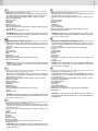
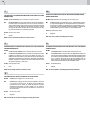
MURATURA DELLA PIASTRA DI FISSAGGIO DEL MOTORIDUTTORE
1
2
3
4
5
6
7
8
9
10
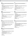
Pavimentazione.
Zanche.
Guaine per cavi ø 25 minimo. Utilizzare per la protezione dei cavi delle guaine
di dimensioni adeguate del tipo pesante approvato. Le guaine devono essere
ricoperte da cemento.
Cavi elettrici (vedere predisposizioni a pag.2).
Piastra di ssaggio che permette la regolazione del motoriduttore in altezza.
Tubo per passaggio cavi.
Staffe che permettono la regolazione orizzontale del motoriduttore.
Dadi.
Motoriduttore.
Apparecchiatura elettronica.
F
UK
WALLING THE GEARMOTOR FASTENING PLATE
1
2
3
4
5
6
7
8
9
10
Flooring.
Feet.
Sheaths for cables ø 25 minimum. Use approved heavy sheaths of the
correct dimensions to protect the cables. The sheaths have to be covered
by cement.
Electrical cables (see page 2).
Fastening plate which allows the gearmotor height to be adjusted.
Tube for laying down the cable.
Brackets that allows horizontal adjustement of the gearmotor.
Nuts.
Gearmotor.
Electronic control unit.
E
P
NL
D
Piso.
Peças de xação.
Tubos para cabos Ø 25 mín. Para a protecção dos cabos usar tubos de di-
mensões adequadas, de tipo pesado aprovado. Os tubos devem ser cobertos
de cimento.
Cabos eléctricos (v. predisposição na pág. 2)
Chapa de xação para a regulação da altura do motorredutor.
Tubo para passagem dos cabos.
Abraçadeiras para a regulação horizontal do motorredutor.
Porcas
Motorredutor
Cartão para a ligação do motor e dos ns-de-curso magnéticos.
Fundering.
Verankeringbouten.
Beschermingbuis voor de kabels f 25 mm. Om de kabels te beschermen is
het aangeraden aangepaste beschermin buizen te gebruiken, aangezien ze
nadien in cement worden bevestigd.
Elektrische kabels (zie p. 2).
Bevestigingsplaat met de mogelijkheid de motor te regelen in de hoogte.
Kabel geleidingbuis.
Montagesteunen om de motor horizontaal af te regelen.
Moeren.
Motorreductor.
Elektronische sturingskast.
Pieds de xation.
Gaines de protection des câbles ø 25 minimum. Pour protéger les câbles,
utiliser des gaines appropriées du type approuvé. Les gaines doivent être
revêtues de ciment.
Câbles électriques (voir les appareillages électriques à la page 2).
Plaque de xation permettant de régler le motoréducteur en hauteur.
Tube de passage des câbles.
Etriers permettant le réglage horizontal du motoréducteur.
Ecrous.
Motoréducteur.
Platine électronique.
Fußboden.
Füsse.
Kabelmäntel min. ø 25. Damit die Kabel geschützt sind, Mäntel angemessener
Größe vom schweren, zugelassenen Typ verwenden. Die Mäntel müssen
durch Zement abgedeckt werden.
Stromkabel (siehe Vorbereitungen auf Seite 2).
Befestigungsplatte, die die Höhenverstellung des Getriebemotors erlaubt.
Rohre für den Kabeldurchgang.
Bügel zur waagrechten Verstellung des Getriebemotors.
Muttern.
Getriebemotor.
Elektronisches Steuergerät.
MAUERUNG DER BEFESTIGUNGSPLATTE DES GETRIEBEMOTORS
1
2
3
4
5
6
7
8
9
10
Pavimentación.
Piés.
Vainas para cables ø 25 mínimo. Para la protección de los cables uitlizar
vainas de dimensiones adecuadas de tipo pesado aprobado; las vainas deben
estar recubiertas de cemento.
Cables eléctricos (ver predisposiciones en pág. 2).
Placa de anclaje para la regulación de la altura del motorreductor.
Tubo para pasar los cables.
Abrazaderas para la regulación horizontal del motorreductor.
Tuercas.
Motorreductor.
Equipo electrónico.
MAMPOSTERÍA DE LA PLACA DE ANCLAJE DEL MORORREDUCTOR
1
2
3
4
5
6
7
8
9
10

6
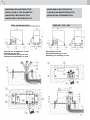
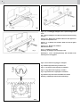
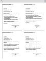
Figure 1, 2 e 4 - Montaggio cremagliera - N.B.: le quote sul disegno sono
in mm
Figs. 1, 2 and 4 - Installing the rack - NOTE: The measurements in the drawing
are in mm
Figures 1, 2 et 4 - Montage de la crémaillière - NOTA: Les cotes rappelées sur
le croquis sont exprimées en mm.
Figuras 1, 2 y 4 - Montaje de la cremallera - NOTA: Las cotas del gráco
están en mm
Figuras 1, 2 e 4 - Montagem da cremalheira.
N.B. Dimensões em mm.
Fig. 1, 2, 4 - Plaatsing van de tandlat.
Opmerking : de afmetingen op de tekening zijn in mm.
Abbildungen 1, 2 und 4 - Zahnstangenmontage - N.B.: Die Maße auf der
Zeichnung sind in mm angegeben.
Figura 3 - Gioco minimo tra ingranaggio e cremagliera
Fig. 3 - Minimum play between the gear and the rack
Figure 3 - Jeu minimum entre l’engrenage et la crémaillere
Figura 3 - Jeugo mínimo entre engranaje y cremallera
Fig. 3 - Folga mínima entre a engrenagem e a cremalheira.
Fig.3 - Minimum vrije ruimte tussen het tandwiel en de tandlat.
Abbildung 3 - Mindestspiel zwischen Rad und Zahnstange
Fig. 4

7
NL
I
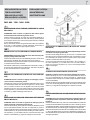
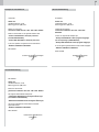
MONTAGGIO DEI FINE CORSA MAGNETICI
Posizionare le due staffe portamagneti (5) sopra la cremagliera (3) alle due estremità del
cancello (4) in posizione di cancello chiuso e cancello aperto con riferimento al sensore (1)
posto sopra la scheda. Montare sulle staffe (5) i due magneti (2) in posizione orizzontale.
N.B.: La distanza dei magneti (2) dal cofano del motoriduttore non deve essere
inferiore a 15 mm.
Posizionare i magneti (2) esattamente in corrispondenza orizzontale del piccolo magnete
(1) montato sulla scheda. I magneti (2) sono polarizzati diversamente tra di loro, uno con
polarizzazione negativa e l’altro con polarizzazione positiva, pertanto il montaggio dei due
magneti sulle staffe (5) va vericato controllando i punti d’arresto muovendo manualmente
il cancello in apertura e chiusura.
N.B.: Le quote sul disegno sono in mm.
F
MONTAGE DES FINS DE COURSE MAGNETIQUES
Positionner les deux étriers porte-aimants (5) sur la crémaillère (3) aux deux extrémités de la
grille (4) (grille fermée et grille ouverte). Se référ au capteur (1) situé au-dessus de la carte.
Monter les deux aimants (2) sur les étriers (5) en position horizontale.
NOTA: La distance des aimants (2) du capot du motoréducteur ne doit pas être
inférieure à 15 mm.
Positionner les aimants (2) exactement au niveau du petit aimant (1) (alignement horizontal)
monté sur la carte. Comme les aimants (2) présentent del pôles oppsées (positif et négatif),
lors de leur montage sur les étriers (5) il faudra contrôller les point d’arrêt. Pour ce faire,
ouvrir et fermer manuellement la grille.
NOTA: Les cotes rappelées sur le croquis sont exprimées en mm.
UK
INSTALLING THE MAGNETIC LIMIT SWITCHES
Place the two brackets that the magnets (5) are mounted on, above the rack (3) at the two
ends of the gate (4) with the gate closed and the gate open in relation to the sensor (1) located
above the card. Install the two magnets (2) in a horizontal position on the brackets (5).
NOTE: The distance of the magnets (2) from the gearmotor’s cover must not be less
than 15 mm.
Place the magnets (2) so that they exactly correspond horizontally with the small magnet (1)
installed on the card. The magnets (2) are polarized differently
from each other: one has negative polarization and other has positive polarization. Therefore
you have to check the installation of the two magnets on the brackets (5). To do this you have
to check the stopping points of the gate by manually opening and closing it.
NOTE: The measurements in the drawing are in mm
E
Posicionar los imanes (2) en correspondencia horizontal respecto al imán (1) montado
sobre la tarjeta. Los imanes (2) están polarizados diferentemente entre sí, uno posee una
polaridad negativa y el otro positiva. Por lo tanto, durante el montaje de los imanes sobre
las abrazaderas (5) deben vericarse los puntos de detención, moviendo manualmente la
puerta en apertura y cierre.
NOTAS: Las cotas del gráco están en mm.
P
MONTAJE DE LOS FINALES DE CARRERA MAGNÉTICOS
Posicionar las dos abrazaderas portaimanes (5) sobre la cremallera (3), en las dos ex-
tremidades de la puerta (4), con posición de puerta cerrada y puerta abierta respecto al
sensor (1) ubicado sobre la tarjeta. Montar los dos imanes (2) sobre las abrazaderas (5)
en posición horizontal.
NOTAS: La distancia de los imanes (2) al capot del motorreductor no debe ser inferior
a 15 mm.
MONTAGEM DOS FINS-DE-CURSO MAGNÉTICOS
Posicionar os dois suportes dos magnetes (5) por cima da cremalheira (3) em ambas as
extremidades do portão (4), em posição de portão fechado e portão aberto com referência
ao sensor (1) situado em cima do cartão. Montar nos suportes (5) os dois magnetes (2)
em posição horizontal.
N.B. A distância dos magnetes (2) ao capot do motorredutor não deve ser inferior a
15 mm.
Posicionar os magnetes (2) exactamente em correspondência horizontal do pequeno
magnete (1) montado no cartão. Os magnetes (2) estão polarizados diversamente entre si,
um com polarização negativa e o outro com polarização positiva e portanto a montagem
dos dois magnetes nos suportes (5) deve ser vericada controlando os pontos de paragem
deslocando manualmente o portão em abertura e em encerramento.
N.B. As medidas indicadas no desenho são em mm.
PLAATSING VAN DE MAGNETISCHE EINDERITSCHAKELAARS
Plaats de 2 montagesteunen waarop de magneten (5) gemonteerd zijn, boven de tandlat
(3) aan beide zijden van het hekken (4), zowel in open als gesloten stand in relatie tot de
sensor (1) bovenop de elektronische kaart. Plaats de 2 magneten (2) horizontaal op de
montagesteunen (5).
OPMERKING : De afstand tussen de magneten (2) en de motorbehuizing mag niet
minder bedragen dan 15 mm.
Plaats de magneten (2) horizontaal tov. de kleine magneet (1) geïnstalleerd op de print. De
magneten (2) zijn verschillend : één is negatief, de andere is positief gepolariseerd. Hierdoor
is het nodig de plaatsing van deze 2 magneten (2) te controleren op de montagesteunen (5),
door de poort manueel te openen en te sluiten.
OPMERKING : De afmetingen op de tekeningen zijn in mm.
D
MONTAGE DER MAGNETISCHEN ENDSCHALTER
Die zwei Magnethaltebügel (5) oberhalb der Zahnstange (3) an den zwei Enden des Tors
(4) bei geschlossenem Tor und bei offenem Tor mit Bezug auf den Sensor (1) oberhalb der
Platine anbringen. An den zwei Bügeln (5) waagrecht die zwei Magneten (2) anbringen.
N.B.: Der Abstand der Magneten (2) von der Getriebemotorhaube darf nicht geringer
als 15 mm sein.
Die zwei Magneten (2) exakt in waagrechter Übereinstimmung mit dem kleinen, an der Platine
befestigten Magneten (1) anbringen. Die Magneten (2) sind unterschiedlich gepolt, einer mit
Minuspolung und einer mit Pluspolung. Deshalb ist die Anbringung der zwei Magneten an
den Bügeln (5) zu überprüfen, indem man durch manuelles Öffnen und Schließen des Tores
die Haltestellen kontrolliert.
N.B.: Die Maße auf der Zeichnung sind in mm angegeben.
Fig. 1 Fig. 2

8
CARDS FOR CONNECTING THE MOTOR AND THE MAGNETIC LIMIT
SWITCHES
M1
M2
M3
M4
R1-R2
C
NOTE: It is absolutely necessary to connect the earth.
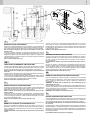
I
SCHEDE PER IL COLLEGAMENTO DEL MOTORE E DEI FINECORSA MA-
GNETICI
M1
M2
M3
M4
R1-R2
C
N.B.: Si raccomanda tassativamente di collegare la terra.
UK
F
E
P
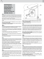
MORSETTIERA per il collegamento del motore monofase. Il morsetto n° 3 è il
comune del motore. Per invertire il senso di rotazione del motore, scambiare
tra di loro i collegamenti sui morsetti 1 e 2.
MORSETTIERA per il collegamento del motore trifase. Per invertire il senso
di rotazione del motore scambiare tra di loro due fasi dell’alimentazione del
motore.
MORSETTIERA per il collegamentto dei necorsa magnetici. Il morsetto 9 è
il comune dei necorsa. I necorsa di apertura e di chiusura sono in funzione
del senso di apertura del cancello. Facendo scorrere il cancello manualmente,
vericare con un tester sulla morsettiera M3 il necorsa di apertura ed il
necorsa di chiusura.
MORSETTIERA per il collegamento tra la scheda ed il motore.
Finecorsa reed.
Magnete.
CARTES POUR LA CONNEXION DU MOTEUR ET DES FINS DE COURSE
MAGNETIQUES
M1
M2
M3
TERMINAL BOARD for connecting the single-phase motor. Terminal n° 3 is
the motor common. To reverse the motor’s rotation, switch the connections
between terminals 1 and 2.
TERMINAL BOARD for connecting the three-phase motor. To reverse the
motor’s direction of rotation, switch two of the motor’s power supply phases.
TERMINAL BOARD for connecting the magnetic limit switches. Terminal 9
is the limit switches’ common. The limit switches for opening and closing are
based on the gate’s opening direction (if it is right or left).
Manually operate the gate. Check the opening limit switch and the closing limit
switch with a tester on terminal board M3.
TERMINAL BOARD for making the connection between the card and the
motor.
Reed limit switch.
Magnet.
M4
R1-R2
C
NOTA: Il est recommandé d’effectuer la mise à la terre.
TARJETAS PARA LA CONEXION DEL MOTOR Y DEL LOS FINALES DE
CARRERA MAGNETICOS
M1
M2
M3
M4
R1-R2
C
NOTA: Se aconseja realizar la conexión a tierra.
CONECTOR DE BORNES para la conexión del motor monofase. El borne 3 es
el común del motor. Para invertir el sentido de rotación del motor, intercambiar
entre sí las conexiones en el borne 1 y 2.
CONECTOR DE BORNES para la conexión del motor trifase. Para invertir el
sentido de rotación del motor, intercambiar entre sí dos fases de la alimen-
tación del motor.
CONECTOR DE BORNES para la conexión de los nales de carrera magnéti-
cos. El borne 9 es el común de los nales de carrera. Los nales de carrera de
apertura y cierre están en función del sentido de apertura de la purta (derecho
o izequierdo). Deslizando manualmente la puerta, vericar con un tester en el
conector de bornes M3 el nal de carrera de apertura y el de cierre.
CONECTOR DE BORNES para la conexión entre la tarjeta y el motor.
Final de carrera reed.
Imán.
CARTÕES PARA A LIGAÇÃO DO MOTOR DO FIM-DE-CURSO
M1
M2
M3
M4
R1-R2
C
N.B. Recomenda-se de efectuar a ligação à instalação de Terra.
M
T
S
R
MOTORE TRIFASE
PASS2500/380
PASS 600-800-1200- 1800- 2500
BOITE A BORNES pour la connexion du moteur monophasé. La borne 3 est
le commun du moteur. Pour inverser le sens de rotation du moteur, échanger
les connexions des bornes 1 et 2.
BOITE A BORNES pour la connexion du moteur triphasé. Pour inverser le sens
de rotation du moteur, échanger deux phases de l’alimentation du moteur.
BOITE A BORNES pour la connexion des ns de course magnétiques. La
borne 9 est le commun des ns de course. Le ns de course d’ouverture et de
fermeture sont fonction du sens d’ouverture de la grille (à droite ou à gauche)
Déplacer manuellement la grille et, à l’aide d’un appareil de contrôle,
BORNES para a ligação do motor monofásico dos quais o borne 3 é comum.
Para inverter o sentido de rotação do motor, trocar as ligações entre os
bornes 1 e 2.
BORNES para a ligação do motor trifásico. Para inverter o sentido de rotação
do motor, trocar as ligações entre dos fases.
BORNES para a ligação dos ns-de-curso magnéticos. O bornes 9 é comum
aos ns-de-curso. Os ns-de-curso de abertura e encerramento são em
função do sentido de abertura do portão. Deslizando manualmente o portão,
vericar com um tester na caixa de bornes M3 o m-de-curso de abertura e o
m-de-curso de encerramento.
BORNES para a ligação entre motor e cartão.
Fim-de-curso “reed”.
Magnete
.
verier la n de course d’ouverture et la n de course de fermeture sur la
boîte à bornes M3.
BOITE A BORNES pour la connexion de la carte au moteur.
Fins de course “reed”.
Aimant.
D
D
GI.BI.DI. PASS 600 - 800
D: CAPACITOR, ONLY FOR 230Vac MOTORS

9
PLATINEN FÜR DEN ANSCHLUSS DES MOTORS UND DER
MAGNETENDSCHALTER
M1
M2
M3
M4
R1-R2
C
N.B.: Es wird empfohlen, unbedingt die Erde anzuschließen.
PASS 800 24 VDC
I
SCHEDE PER IL COLLEGAMENTO DEL MOTORE E DEI FINECORSA
MAGNETICI
M1-M2
M3
R1-R2
C
N.B.: Si raccomanda tassativamente di collegare la terra.
MORSETTIERA per il collegamento del motore a 24 Vdc.
MORSETTIERA per il collegamentto dei necorsa magnetici. Il
morsetto 9 è il comune dei necorsa. I necorsa di apertura e di
chiusura sono in funzione del senso di apertura del cancello. Facen-
do scorrere il cancello manualmente, vericare con un tester sulla
morsettiera M3 il necorsa di apertura ed il necorsa di chiusura.
Finecorsa reed.
Magnete.
UK
NL
KLEMMENLEISTE für den Anschluss des Einphasenmotors. Die Klemme
Nr. 3 ist die Sammelklemme des Motors. Zur Umkehrung der Drehrich-
tung des Motors, die Anschlüsse auf den Klemmen 1 und 2 miteinander
vertauschen.
KLEMMENLEISTE für den Anschluss des Dreiphasenmotors. Zur Um-
kehrung der Drehrichtung des Motors zwei Phasen der Versorgung des
Motors miteinander vertauschen.
KLEMMENLEISTE für den Anschluss der Magnetendschalter. Die Klemme
9 ist die Sammelklemme der Endschalter. Die Endschalter für das Öffnen
und das Schließen sind in der Öffnungsrichtung des Tors in Funktion.
Wenn das Tor mit der Hand gefahren wird, mit einem Tester auf der
Klemmenleiste M3 den Endschalter für das Öffnen und den Endschalter
für das Schließen prüfen.
KLEMMENLEISTE für den Anschluss zwischen der Platine und dem
Motor.
Endschalter Reed.
Magnet.
ELECTRONISCHE PRINT VOOR AANSLUITING VAN DE MOTOR EN DE
MAGNETISCHE EINDSCHAKELAARS
M1
M2
M3
M4
R1-R2
C
N.B.: Het is aan te raden de aarding aan te sluiten.
AANSLUITKLEM voor aansluiting van de monofasige motor. Klem 3 is
gemeenschappelijke. Om de richting van de motor om te draaien wijzigt
men de aansluitingen tussen klem 1 en 2.
AANSLUITKLEM voor aansluiting van de driefasige motor. Om de richting
van de motor om te draaien wijzigt men de fases van de voeding van de
motor.
AANSLUITKLEM voor aansluiting van de eindschakelaars. Klem 9 is de
gemeenschappelijke van de eindschakelaars. De eindschakelaars openen
en sluiten zijn gebaseerd op de openrichting van de poort (links of rechts).
Verplaats manueel het hekken, controleer de eindschakelaars openen en
sluiten op de aansluitklem M3.
AANSLUITKLEM voor aansluiting van de print aan de motor.
Eindschakelaar “reed”.
Magneet.
D
TERMINAL BOARD for connecting the 24 Vdc motor.
TERMINAL BOARD for connecting the magnetic limit switches.
Terminal 9 is the limit switches’ common. The limit switches for
opening and closing are based on the gate’s opening direction (if
it is right or left).
Manually operate the gate. Check the opening limit switch and the
closing limit switch with a tester on terminal board M3.
Reed limit switch.
Magnet.
CARDS FOR CONNECTING THE MOTOR AND THE MAGNETIC LIMIT
SWITCHES
M1-M2
M3
R1-R2
C
NOTE: It is absolutely necessary to connect the earth.
La pagina si sta caricando...

11
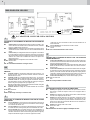
REGOLAZIONE DELLA FORZA
REGLAGE DE LA FORCE
FORCE ADJUSTMENT
REGULACIÓN DE LA FUERZA
REGULAÇÃO DA FORÇA
I
REGISTRAZIONE DELLA FRIZIONE (LIMITATORE DI COPPIA
MECCANICO)
ATTENZIONE: Prima di iniziare la regolazione della frizione togliere
tensione disinserendo l’interruttore generale di linea.
Inserire la chiave a brugola (4), da cinque per il motoriduttore PASS 800 e
da sei per i motoriduttori PASS 1200-1800, nella sede (2) tenendo presente
che ruotando la chiave in senso orario la forza di spinta aumenta, ruotandola
in senso antiorario diminuisce.
Nel caso che ruotando la chiave a brugola ruoti anche l’albero, far combaciare
le due sedi (1), quella sull’albero con quella sulla angia, quindi inserire un
cacciavite (3) e con la chiave a brugola regolare la frizione.
UK
ADJUSTING THE CLUTCH (MECHANICAL TORQUE LIMITER)
ATTENTION: Before beginning to adjust the clutch, disconnect the power
supply by turning off the main switch.
Insert the size 5 Allen wrench (4) for the PASS 800 gearmotor, and the size 6
Allen wrench for the PASS 1200-1800 gearmotors into the socket (2).
Remember that turning the wrench clockwise increases the thrust and turning
it counterclockwise decreases the thrust.
If the shaft also rotates when you turn the Allen wrench, line the two sockets (1)
up (the one on the shaft with the one on the ange). Then insert a screwdriver
(3) and use the Allen wrench to adjust the clutch.
E
REGULACION DEL EMBRAGUE (REGULADOR DE FUERZA DE
EMPUJE MECANICO)
ATTENCION: Antes de comenzar la regulación del embrague, quitar la
tensión accionando el interruptor general de línea.
Introducir la llave allen (4), de cinco para el motorreductor PASS 800 y de sies
para los motorreductores PASS 1200-1800, en el alojamiento (2). Tener en
cuenta que girando la llave en sentido horario la fuerza aumenta y en sentido
antihorario disminuye. Si al girar la llave allen también gira el árbol, juntar los
dos alojamientos (1), el que estáen el árbol con el que está en la brida. Luego
introducir un destornillador (3) y regular el embrague con la llave allen.
NL
REGULAÇÃO DA EMBRAIAGEM (LIMITADOR DE TORQUE
MECÂNICO)
ATENÇÃO: Antes de iniciar a regulação da embraiagem desligar a tensão
accionando o interruptor geral de linha.
Introduzir a chave hexagonal-macho (4), de 5 mm para o motorredutor PASS
800 e de 6 mm para o motorredutor PASS 1200-1800, no alojamento (2). Tomar
em consideração que rodando a chave no sentido horário a força aumenta,
rodando no sentido anti-horário a força diminui.
Se ao girar da chave hexagonal-macho gire também o eixo no sentido, jun-
tar os dois alojamentos (1), o que está no eixo com o que está na ange, e
apertar com uma chave de parafusos (3) e com a chave hexagonal-macho
regular a embraiagem.
P
AFREGELING VAN DE MECHANISCHE SLIPKOPPELING
OPGELET : Schakel de stroom uit alvorens de koppeling af te regelen.
Steek de sleutel (4) van 5 mm. voor de motorreductor PASS 6 en die van 6
mm. voor de motorreducto ren 12-18-25 in de opening (2). Vergeet niet dat
uurwijzerzin draaien verhogen van de kracht en tegen uurwijzerzin verlagen
van de kracht betekent.
Wanneer de sleutel en de as gelijkertijd draaien, lijn dan de 2 inkepingen (deze
van de as en de behuizing) tegenover mekaar uit en steek er een schroeven-
draaier (3) in. Regel dan de koppelingen door middel van de sleutel.
D
KRACHTREGELING
EINSTELLUNG DER KUPPLUNG (MECHANISCHE RUTSCHKUPP-
LUNG)
ACHTUNG: Bevor man mit der Einstellung der Kupplung beginnt, den
Leitungshauptschalter ausschalten, damit keine Spannung mehr vor-
handen ist.
Den Sechskantstiftschlüssel (4), einen 5er für den Getriebemotor PASS 800
und einen 6er für die Getriebemotoren PASS 1200-1800, in den Sitz (2) stecken
und dabei berücksichtigen, daß durch Drehen des Schlüssels im Uhrzeigersinn
die Schubkraft erhöht, durch Drehen gegen Uhrzeigersinn verringert wird.
Sollte sich beim Drehen des Schlüssels auch die Welle drehen, die zwei Sitze
(1), den an der Welle mit dem am Flansch in Übereinstimmung bringen, und
einen Schraubenzieher (3) hineinstecken und mit dem Sechskantstiftschlüssel
die Kupplung einstellen.
PASS 800 - 1200 - 1800 - 2500
KRAFTEINSTELLUNG
F
REGLAGE DE L’EMBRAYAGE (LIMITEUR DE COUPLE MECANI-
QUE)
ATTENTION: Avant de commencer le réglage de l’embrayage, couper le
courant à l’aide de l’interrupteur général.
Introduire la clé (4) de 5 mm pour le motoréducteur PASS 800 et de 6 mm pour
les motoréducteurs PASS 1200-1800 dans le logement (2). Ne pas oublier
que si l’on tourne la clé dans le sens des aiguilles d’une montre, la poussée
augmente et vice-versa. Si la clé et l’arbre tournent en même temps, aligner
les deux logements (1) (celui de l’arbre et celui de la bride) et donc introduire
un tournevis (3). Régler l’embrayage à l’aide de la clé.

12
MANOVRA MANUALE
MANOUVRE MANUELLE
MANUAL OPERATION
MANIOBRA MANUAL
MANOBRA MANUAL
I
F
UK
E
P
In caso di guasto o di mancanza di corrente, per la manovra manuale ruotare il
coperchietto (4), inserire la chiave (3) e ruotarla in senso orario, verso destra,
senza forzarla. La chiave (3) uscirà di alcuni millimetri spinta da una molla. Qundi
agire sulla maniglia (1) e ruotarla completamente di 180° verso sinistra; a questo
punto si può aprire e chiudere il cancello manualmente.
Per il ripristino in automatico ruotare la maniglia (1) nella posizione iniziale,
spingere la chiave (3) in avanti, ruotarla in senso antiorario, verso sinistra, quindi
estrarla.
N.B.: Se la chiave (3) non è spinta completamente in avanti, la stessa non
ruota e non può essere estratta.
La maniglia (1) può essere bloccata agendo come sopra sulla chiave (3)
anche in posizione di manovra manuale.
En cas de défaillance ou de coupure de courant, pour effectuer la manoeuvre
manuelle tourner le couvercle (4), enforcer la clé (3) et la tourner dans le sens
des aiguilles d’une montre (vers la droite) sans la forcer.
Comme elle est poussée par un ressort, la clé (3) sort de quelques millimètres.
Agir sur la poignée (1) et la tourner complètement de 180° vers la gauche.
A ce moment-là, il est possible d’ouvrir et de fermer manuellement la grille.
Pour rétabilir le fonctionnement automatique, remettre la poignée (1) à l’ètat initial,
pousser la clé (3), la tourner dans le sens inverse des aiguilles d’une montre (vers
la gauche) et donc la sortie.
NOTA: Si la clé (3) n’est pas poussée à fond, elle ne tourne pas et donc il est
impossible de la sortir de son logement.
La poignée (1) peut être bloquée à l’aide de la clé (3) (voir ci-dessus) même
lors d’une monoeuvre manuelle.
You can manually operate the gate if a problem occurs or if the power supply fails.
To manually operate the gate, carry out the following procedure:
rotate the cover (4), insert the key (3), and turn it clockwise (to the right) without
forcing it. The key (3) will be pushed out a few millimeters by a spring. Then
completely turn the handle (1) 180° towards the left. You can now manually open
and close the gate.
To automatically reset it, turn the handle (1) to its initial position, push the key (3)
forward, turn it counterclockwise (to the left), and then remove it.
NOTE: If the key (3) is not completely pushed forward, it will not turn and
cannot be removed.
The handle (1) can even be locked in the manual position by following the
above procedure with the key (3).
En caso de avería o de corte de energía eléctrica, para la maniobra manual girar
la tapa (4), introducir la llave (3) y girarla en sentido horario sin forzarla. La llave
(3) saldrá algunos milímetros empujada por un resorte. Accionar la manija (1)
y girarla completamente (180°) hacia la izquierda; ahora resulta posible abrir y
cerrar manualmente la puerta.
Para restablecer el funcionamiento automático, girarla manija (1) hacia la posi-
ción inicial, empujar la llave (3) hacia adelante, girarla en sentido antihorario (a
izquierda) y luego extraerla.
No caso de avaria ou de falta de corrente, para manobrar manualmente o portão
rodar a tampa (4), introduzir a chave (3) e rodar no sentido horário, para a direita,
sem a esforças. A chave (3) sairá de alguns milímetros pressionada por uma mola.
A seguir agir no manípulo (1) rodando-a completamente de 180° para a esquerda;
a este ponto pode-se abrir e fechar manualmente o portão. Para restabelecer o
automatismo rodar o manípulo (1) na posição inicial, pressionar a chave (3) para
a frente, rodando-a no sentido anti-horário para a esquerda e retirar a chave.
N.B. Se a chave (3) não está completamente pressionada para a frente não
roda e portanto não pode ser extraída.
O manípulo (1) pode ser bloqueado do mesmo modo que a chave (3) também
na posição de manobra manual.
NOTA: Si la llave (3) no es empujada totalmente hacia adelante, la misma
no gira y no puede ser extraida.
La manija (1) puede bloquearse de la misma manera que la llave (3), incluso
en posición de maniobra manual.
NL
D
MANUELE ONTGRENDELING
Im Falle eines Defekts oder Stromausfalls, zur Bewegung von Hand den Deckel
(4) beiseite drehen, den Schüssel (3) hineinstecken und ohne Gewaltanwendung
im Uhrzeigersinn nach rechts drehen. Der Schlüssel (3) wird durch eine Feder ge-
schoben und um einige mm herausgehen. Dann den Griff (1) nehmen und völlig um
180° nach links drehen. Jetzt kann man das Tor von Hand öffnen und schließen.
Zur Wiederherstellung der automatischen Funktion den Griff (1) wieder in die
anfängliche Stellung bringen, den Schlüssel (3) nach vorne schieben, gegen
Uhrzeigersinn nach links drehen und dann abziehen.
N.B.: Wurde der Schlüssel (3) nicht ganz nach vorne geschoben, dreht er
sich nicht und läßt sich nicht abziehen.
Der Griff (1) kann blockiert werden, indem man wie oben den Schlüssel (3)
verstellt, auch in der Stellung manuelle Bewegung.
BEWEGUNG VON HAND
Ingeval van stroomonderbreking kan het hekken manueel bediend worden als
volgt :
Draai het afdekplaatje (4) weg, steek de sleutel (3) in het ontgren delingsmechanisme
en draai deze in uurwijzerzin zonder grote krach ten te gebruiken. De sleutel (3)
wordt enkele mm. uitgeduwd door een veer. Draai dan de hendel (1) 180° naar
de linkerzijde. Nu kan het hekken manueel geopend en gesloten worden. Om het
hekken automatisch te bedienen, plaats de hendel (1) in de originele positie, druk
de sleutel (3) in, draai hem tegen uurwijzer zin en verwijder hem.
OPMERKING : Wanneer de sleutel (3) niet volledig ingedrukt is kan hij noch
draaien, noch verwijderd worden.
La pagina si sta caricando...

14
Dichiarazione di conformità CE
Il fabbricante:
GI.BI.DI. S.r.l.
Via Abetone Brennero, 177/B,
46025 Poggio Rusco (MN) ITALY
Dichiara che i prodotti:
motoriduttori: PASS 600 - 800 - 1200 - 1800 - 2500 -
800/24VDC
Sono conformi alle seguenti Direttive CEE:
• Direttiva LVD 2006/95/CE e successive modiche
(escluso PASS 800/Vdc);
• Direttiva EMC 2004/108/CE e successive modiche;
e che sono state applicate le seguenti norme armonizzate:
• EN60335-1, EN61000-6-3, EN61000-6-1
Data 05/06/08
Firma Ammistratore Delegato
Oliviero Arosio
Déclaration de conformité CE
La société:
GI.BI.DI. S.r.l.
Via Abetone Brennero, 177/B,
46025 Poggio Rusco (MN) ITALY
Déclare que les produits:
motoreducteur: PASS 600 - 800 - 1200 - 1800 - 2500 -
800/24VDC
Sont en conformité avec les exigences des Directives CEE
:
• Directive LVD 2006/95/CE et ses modications
(exclu PASS 800/24Vdc);
• Directive EMC 2004/108/CE et ses modications;
et que les normes harmonisées suivantes ont été appliquées :
• EN60335-1, EN61000-6-3, EN61000-6-1
Date 05/06/08
Firma Ammistratore Delegato
Oliviero Arosio
CE Declaration of conformity
The manufacturer:
GI.BI.DI. S.r.l.
Via Abetone Brennero, 177/B,
46025 Poggio Rusco (MN) ITALY
Declares that the products:
gearmotor: PASS 600 - 800 - 1200 - 1800 - 2500 - 800/24VDC
Are in conformity with the following CEE Directives:
• LVD Directive 2006/95/CE and subsequent amendments
(excluded PASS 800/24Vdc);
• EMC Directive 2004/108/CE and subsequent amendments;
and that the following harmonised standards have been applied:
• EN60335-1, EN61000-6-3, EN61000-6-1
Date 05/06/08
Managing Director
Oliviero Arosio
Declaración de conformidad CE
El fabricante:
GI.BI.DI. S.r.l.
Via Abetone Brennero, 177/B,
46025 Poggio Rusco (MN) ITALY
Declara que los productors:
motorreductor: PASS 600 - 800 - 1200 - 1800 - 2500 -
800/24VDC
Cumplen la siguiente Directiva CEE:
• Directiva LVD 2006/95/CE y modicaciones sucesivas
(excluido PASS 800/24Vdc);
• Directiva EMC 2004/108/CE y modicaciones sucesivas;
y que se han aplicado las siguientes normas armonizadas:
• EN60335-1, EN61000-6-3, EN61000-6-1
Fecha 05/06/08
Signature Administrateur Délégué
Oliviero Arosio
La pagina si sta caricando...

GI.BI.DI. S.r.l.
Via Abetone Brennero, 177/B
46025 Poggio Rusco (MN) - ITALY
Tel. +39.0386.52.20.11
Fax +39.0386.52.20.31
E-mail: [email protected]
Numero Verde: 800.290156
www.gibidi.com
AIC3090 - 06/08 - REV07
-
 1
1
-
 2
2
-
 3
3
-
 4
4
-
 5
5
-
 6
6
-
 7
7
-
 8
8
-
 9
9
-
 10
10
-
 11
11
-
 12
12
-
 13
13
-
 14
14
-
 15
15
-
 16
16


in altre lingue
- English: GiBiDi PASS Owner's manual
- français: GiBiDi PASS Le manuel du propriétaire
- español: GiBiDi PASS El manual del propietario
- Deutsch: GiBiDi PASS Bedienungsanleitung
- Nederlands: GiBiDi PASS de handleiding
- português: GiBiDi PASS Manual do proprietário
Documenti correlati


Altri documenti
-
Metabo BSA 14.4-18 LED Istruzioni per l'uso
-
 Roger Technology BRUSHLESS BG30/1804/HS Guida d'installazione
-
Key Gates Turbo 30 Guida utente
-
Genius SPRINT 05 Istruzioni per l'uso
-
Tau T-One Manuale del proprietario
-
Genius BRAIN03 BRAIN04 Istruzioni per l'uso
-
-
-
-
 quiko PUMA2015 Manuale utente

