

2
Le informazioni contenute in questo documento sono state attentamente redatte e
controllate. Tuttavia non è assunta alcuna responsabilità per eventuali inesattezze.
Tutti i diritti sono riservati e questo documento non può essere copiato, fotocopiato,
riprodotto per intero o in parte senza previo consenso scritto della D.T.S .
D.T.S. si riserva il diritto di apportare senza preavviso cambiamenti e modifiche
estetiche , funzionali o di design a ciascun proprio prodotto. D.T.S non assume alcuna
responsabilità sull’uso o sull’applicazione dei prodotti o dei circuiti descritti.
The information contained in this publication has been carefully prepared and
checked. However, no responsibility will be taken for any errors. All rights are
reserved and this document cannot be copied, photocopied or reproduced, in part or
completely, without prior written consent from D.T.S.
D.T.S. reserves the right to make any aesthetic, functional or design modifications to
any of its products without prior notice. D.T.S. assumes no responsibility for the use or
application of the products or circuits described herein.
Les informations contenues dans le présent manuel ont été rédigées et contrôlées
avec le plus grand soin. Nous déclinons toutefois toute responsabilité en cas
d'éventuelles inexactitudes. Tous droits réservés. Ce document ne peut être copié,
photocopié ou reproduit, dans sa totalité ou partiellement, sans le consentement
préalable de D.T.S.
D.T.S. se réserve le droit d'apporter toutes modifications et améliorations esthétiques,
fonctionnelles ou de design, sans préavis, à chacun de ses produits. D.T.S. décline
toute responsabilité sur l'utilisation ou sur l'application des produits ou des circuits
décrits.
Las informaciones contenidas en este documento han sido cuidadosamente
redactadas y controladas. Con todo, no se asume ninguna responsabilidad por
eventuales inexactitudes. Todos los derechos han sido reservados y este documento
no puede ser copiado, fotocopiado o reproducido, total o parcialmente, sin previa
autorización escrita de D.T.S.
D.T.S. se reserva el derecho a aportar sin previo aviso cambios y modificaciones de
carácter estético, funcional o de diseño a cada producto suyo. D.T.S. no se asume
responsabilidad de ningún tipo sobre la utilización o sobre la aplicación de los
productos o de los circuitos descritos.

3
INDEX:
1- SYMBOLS ................................................................................................................. 4
2- GENERAL WARNING .............................................................................................. 5
3- GENERAL WARRANTY CONDITIONS .................................................................... 5
4- TECHNICAL FEATURES ......................................................................................... 5
5- ACCESSORIES ........................................................................................................ 7
6- IMPORTANT SAFETY INFORMATION .................................................................... 8
6.1 Fire prevention...................................................................................................... 8
6.2 Prevention of electric shock .................................................................................. 8
6.3 Safety ................................................................................................................... 8
6.4 Level of protection against the penetration of solid and liquid objects .................. 8
6.5 Waste Electrical and Electronic Equipment (WEEE) directive .............................. 9
7- INSTALLATION ........................................................................................................ 9
7.1 Protection against liquids .................................................................................... 11
7.2 Movement ........................................................................................................... 11
7.3 Risk of fire .......................................................................................................... 11
7.4 Forced ventilation ............................................................................................... 12
7.5 Ambient temperature .......................................................................................... 12
8- INPUT / OUTPUT CONNECTIONS ......................................................................... 12
8.1 Internal fuse ........................................................................................................ 13
9- DMX SIGNAL CONNECTION .............................................................................. 14
9.1 DMX Addresses .................................................................................................. 15
9.2 Selecting the DMX address ................................................................................ 15
10- RDM FUNCTIONS ................................................................................................ 15
11- FIRMWARE UPDATING ....................................................................................... 16
12- DISPLAY FUNCTIONS ......................................................................................... 17
13- REC MODE ........................................................................................................... 20
14- ERROR MESSAGES ............................................................................................ 20
15- PERIODIC CLEANING ......................................................................................... 21
16- PERIODIC CONTROLS ........................................................................................ 21
17- HOLOGRAPHIC FILTER INSTALLATION ........................................................... 22
18- LENSES SET REPLACEMENT ............................................................................ 23
19- BARNDOOR INSTALLATION .............................................................................. 24
20- DMX PROTOCOL ................................................................................................. 25

4
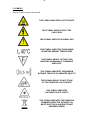
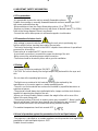
1- SYMBOLS
Graphic symbols used on this manual:
THIS SYMBOL INDICATES A HOT SURFACE
THIS SYMBOL INDICATES ELECTRIC
SHOCK RISK
THIS SYMBOL INDICATES GENERAL RISK
THIS SYMBOL INDICATES THE MAXIMUM
OPERATING AMBIENT TEMPERATURE
THIS SYMBOL MEANS “SUITABLE FOR
MOUNTING ON NORMALLY FLAMMABLE
SURFACES”
THIS SYMBOL INDICATES THE MINIMUM
DISTANCE FROM THE ILLUMINATED OBJECTS
THIS SYMBOL MEANS “DO NOT STARE
AT THE OPERATING LIGHT SOURCE”
THIS SYMBOL INDICATES
PHOTOBIOLOGICAL SAFETY
THIS SYMBOL INDICATES THE EUROPEAN
COMMUNITY DIRECTIVE 2012/19/EC ON
WASTE ELECTRICAL AND ELECTRONIC
EQUIPMENT (WEEE)
!

5
2- GENERAL WARNING
Read the instruction contained in this user manual carefully, as they give important
information regarding safety during installation, use and maintenance.
The unit is not for household use and must be installed by a qualified electrician or
experienced person.
Always disconnect the device from the mains before maintenance.
The device must always be equipped with an efficient ground connection.
3- GENERAL WARRANTY CONDITIONS
The unit is guaranteed for 36 months from the date of purchase against manufacturing
material defects.
4- TECHNICAL FEATURES
OVERVIEW
The new BRICK is a high power, very compact, self-contained, IP65 LED Wash light.
BRICK is suitable for various purposes, offering a range of projection angles quickly
interchangeable (no tools required).
BRICK comes with an IP65 power cable plus 2 DMX cables with M / F XLR
connectors (all IP65), that make it perfect for temporary lighting applications, but also
for safe long-lasting installations.
Built with top quality components, BRICK gives you the best value for money by
efficient design and full production automation.
DTS product codes:
03.LDB100S11FC08 BRICK FC ULTRA-NARROW lenses Black finishing
Available on demand:
03.LDB100S11FC10 BRICK FC NARROW lenses Black finishing
03.LDB100S11FC25 BRICK FC MEDIUM Flood lenses Black finishing
03.LDB100S11FC40 BRICK FC WIDE Flood lenses Black finishing
LED Technology
24 x OSTAR STAGE “N” FULL RGBW LEDs
Optical group
8° projection angle
Range of quick-mounting holographic filters included: 20° / 40° / 60°x10° (no mounting
tools required)
Uniform projection on surfaces
Color generation
16 million colors
Wide palette of pure uniform Whites with variable linear color temperature (2700K –
8000K)

6
4- TECHNICAL FEATURES
Control
DMX 512 / RDM
10 DMX channels (Default)
4-digit 7-segment LED display + 4 soft keys
Protection
IP 65
Power supply
Built-in full-range PSU 100-240Vac 50-60 Hz
Consumption: 400VA Max
Connections
Power supply: 3 x 1 sq mm cable (1,5 m length)
DMX In/Out: 0,7 m cable with XLR 5 pins IP65 connector
Operating ambient temperature
-10° / 40°
Weight
10 Kg
Certifications
2014/35/UE ; 2014/30/UE
IEC 62471 ; IEC 695-2-1
EN 60598-1 ; EN 62471 ; EN 61347-2-13
EN 60598-2-17 ; EN 55015 EMC ; EN 61347-1

7
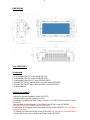
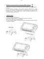
DIMENSIONS
5- ACCESSORIES
As standard
1 x Holographic filter 20° (code 0506A043.D11)
1 x Holographic filter 40° (code 0506A045.D11)
1 x Holographic filter 60°x10° (code 0506A092.D11)
1 x PowerCON TRUE1 female cable connector (code 0520P066)
1 x PowerCON TRUE1 male cable connector (code 0520P067)
1 x User’s Manual
Optional (on request)
- Bracket for ground installation (code 03.LA.213)
- Barndoor black finishing (code 03.LA.210)
- Permanent installation kit IP68: Power connector + 2 x DMX In/Out connectors (code
03.LA.214)
- Aliscaf clamp for tube diameter 50 mm (Max load 100 Kg) (code 0521A008)
(indicated for any kind of loads vertical / horizontal)
- Professional Quick trigger clamp (Max load 100 Kg) (code 0521A037) (not indicated
for horizontal load)
- “C” Clamp G60 (Max load 50 Kg) (code 0521A004) (not indicated for horizontal load)
- Safety cable 3 mm x 60 cm (Max load 60 Kg) (code 0521A010)

8
6- IMPORTANT SAFETY INFORMATION
6.1 Fire prevention:
-It is permissible to place the unit on normally flammable surfaces.
Suitable for mounting on normally flammable materials surfaces greater than 200°C
with some combustion time lag.
-Minimum distance from the closest illuminable surface: 0,5 m.
-Replace any blown or damaged fuses only with those of identical value (T 5A 250V).
Refer to the wiring diagram if there is any doubt.
-Connect the unit to mains power via a thermal magnetic circuit breaker.
6.2 Prevention of electric shock:
-High voltage is present inside the unit. Unplug the unit prior to performing any
function which involves touching the inside of the projector.
-The level of technology inherent in the BRICK requires the assistance of specialised
personnel for all servicing.
Please refer to an authorised DTS service centre.
-A good earth connection is essential for proper functioning of the unit.
-Never connect the unit without proper earth connection.
-The fixture should be located in places with a good air ventilation.
6.3 Safety:
-Risk Group 2 product according to EN 62471.
CAUTION. Do not look directly into the light output. May be harmful to the eyes and
skin.
-Do not stare at the operating light source.
-The light source contained in this luminaire shall only be replaced by the
manufacturer or his service agent or a similar qualified person.
-The unit is not for household use and must be installed by a qualified electrician or
experienced person.
-The projector should always be installed with bolts, clamps and other tools that are
capable of supporting the weight of the unit.
-Always use a second safety cable to sustain the weight of the unit in case of the
failure of the main fixing point.
-The external surface of the unit, at various points, may exceed 60°C. Never handle
the unit until at least 5 minutes have elapsed since the projector was turned off.
-Never install the fixture in an enclosed area lacking sufficient air flow.
The ambient temperature should not exceed 40°C.
6.4 Level of protection against the penetration of solid and liquid objects:
-The projector is classified as an outdoor appliance and its protection level against the
penetration of solid and liquid objects is IP65.
Suitable for wet locations.
!
!

9
6.5 Waste Electrical and Electronic equipment (WEEE) directive:
-The machine, accessories and packaging should be sorted for environmetal-friendly
Recycling.
For EC countries: according to the European Directive 2012/19/EC for Waste
Electrical and Electronic Equipment and its implementation into national right,
luminaires that are no longer usable must be collected separately and disposed of in
an environmentally correct manner.
7- INSTALLATION
The unit is suitable for wet locations.
For outdoor installation, BRICK is provided with a Display UV Protection.
BRICK may be either floor or ceiling mounted.
For floor mounting installation, a bracket with 4 rubber mounting feet (code 03.LA.213)
is available on demand.

10
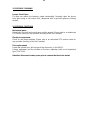
7- INSTALLATION
For ceiling mounted installation, it is recommended the use of appropriate clamps to fix
the unit to the mounting surface.
The supporting structure from which the unit is hung should be capable of bearing the
weight of the unit, as should any clamps used to hung it.
For outdoor application where BRICK needs to be installed vertically keep the
unit display towards the floor.
A permanent installation kit IP68 (code 03.LA.214) is available on demand.
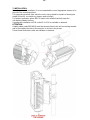
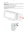
ATTENTION:
A safety cable (code 0521A010) must be securely fixed to the unit’s mounting bracket
and to the support structure of the projector as shown in the picture.
Fixing clamps and safety cable are available on demand.

11
7.1 Protection against liquids
If IP65 protection is impaired for any reason, do not expose this product to external
atmospheric agents, because it could be damaged.
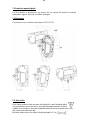
7.2 Movement
The projector has a maximum movement of 110° for Tilt.
7.3- Risk of fire
Each fixture produces heat and must be installed in a well-ventilated place.
It is permissible to place the unit on normally flammable materials surfaces.
Suitable for mounting on normally flammable materials surfaces greater than 200°C
with some combustion time lag.
Minimum distance from the object being illuminated is 0,5 m.

12
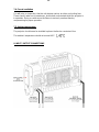
7.4- Forced ventilation
You will note, on inspection, that the unit features various air inlets and cooling fans.
These should, under no circumstances, be blocked or obstructed whilst the projector is
in operation. Doing so could cause the fixture to seriously overheat thereby
compromising its proper operation.
7.5- Ambient temperature
The projector should never be installed in places that lack a constant air flow.
The ambient temperature should not exceed 40°C.
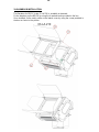
8- INPUT / OUTPUT CONNECTIONS

13
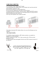
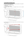
8.1- Internal Fuse
Attention: the fuse replacement must be made by DTS personnel or
experienced person.
Wrong operations can damage the IP65 protection.
To access the internal fuse loose the 6 marked screws which fix the lateral cover on
display panel opposite side and remove the cover.
Use only replacement fuses rated T 5A 250V.
Paying attention to the gasket put in place the lateral cover and fix it with the 6 screws
previously removed.

14
9- DMX SIGNAL CONNECTION:
The unit operates using a digital DMX 512 signal.
Connection between the controller and the unit or between units must be carried out
using a two pair screened ø 0.5 mm.
Ensure that the conductors do not touch each other.
Do not connect the cable ground to the DMX connector chassis.
The plug housing must be isolated. Connect the mixer signal to the DMX IN projector
plug and connect it to the next projector by connecting the DMX OUT plug on the first
unit to the DMX IN plug of the second one.
In this way, all the projectors are cascade connected.
If the display showing the DMX address flashes, then one of the following errors has
occurred:
- DMX signal not present
- DMX reception problem
For Installations where long distance DMX cable connections are needed, we
suggest to use a DMX terminator.
The DMX terminator is a male XLR 3-5 pins connector with a 120 ohm resistor
Between pin 2 and 3.
The DMX terminator must be plugged into the last unit (DMX out panel connector) of
the DMX line.
PLACE A 120 OHM RESISTOR BETWEEN PIN 2
AND 3 OF A MALE XRL CONNECTOR AND PLUG IT
INTO THE DMX OUT PANEL CONNECTOR OF THE
LAST UNIT CONNECTED TO THE DMX LINE
1
2
3
5
4
OUT
120 ohm
PIN 3
PIN 2

15
9.1 DMX addresses
BRICK can be controlled with 10 DMX channels (Default).
In order to use the unit in 10 DMX channels mode (Default), set the following
addresses on the mixer:
Projector 1 A001
Projector 2 A011 If you want to select the next projector, just add “10”
Projector 3 A021
….. A….
projector 6 A051
9.2 Selecting the DMX address
1) Press the UP-DOWN key until you reach the required DMX address. The numbers
on the display will start to flash (but the new DMX address hasn't yet been set).
2) Press ENTER to confirm your selection. The numbers on the display will stop
flashing and the projector is now controlled by the new DMX address.
TIPS: if you keep pushed the UP or DOWN keys, the channels are calculated more
quickly and you get a faster selection.
2) Press ENTER to confirm your selection. The numbers on the display will stop
flashing and the projector is now controlled by the new DMX address.
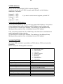
10- RDM FUNCTIONS
By using a RDM controller it is possible to set DMX address, DMX mode and other
parameters.
BRICK accepts the following RDM commands:
DEVICE_INFO
To read the following parameters:
RDM protocol version
Fixture model ID
Fixture type
Software version ID
DMX channels
DMX mode
DMX address
Total sub-fixtures
Total sensors
IDENTIFY_DEVICE
All LED channels ON at max power to identify the
fixture
DMX_START_ADDRESS
To read / set the DMX address
SOFTWARE_VERSION_LABEL
Software version ID
SUPPORTED_PARAMETERS
List of all supported parameters
PARAMETER_DESCRIPTION
Description / details of Manufacturer Specific
parameter as “NO DMX ACTION”
DMX_PERSONALITY
To set the DMX mode
DMX_PERSONALITY_DESCRIPTION
Description / details of the DMX mode
DEVICE_MODEL_DESCRIPTION
Description / details of the Fixture model
MANUFACTURER_LABEL
Producer ID
SENSOR_DEFINITION, SENSOR VALUE
LED Temperature

16
10- RDM FUNCTIONS
RDM MANUFACTURER-SPECIFIC PIDs
NO DMX ACTION
To set the desired fixture’s behavior in case DMX
signal is missing or not available.
1 = Black-out
2 = CHPR (demo program steps 01..16 same as
menu “NDMX > CHPR”)
3 = All channels @ 100%
4 = CUSTOM (RGBW values set into the menus
“RED NO DMX”
“GREEN NO DMX”
“BLUE NO DMX”
“WHITE NO DMX”
5 = Keep last valid DMX signal
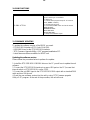
11- FIRMWARE UPDATING
To update the software version of the BRICK you need:
- DTS RED BOX interface (DTS Code 03.LA.008).
- USB-DMX Driver for the DTS RED BOX interface.
- “DTS Firmware Upgrade Utility v.2.02” program installed on PC.
- Latest firmware release available for BRICK unit.
Updating the software version.
Please follow the procedure below to perform the update:
1. Install the DTS RED BOX USB-DMX driver on the PC you will use to update the unit
software.
2. Connect the DTS RED BOX interface to a spare USB port on the PC (be sure that
internal switch on DTS RED BOX is set to COM).
3. Connect the unit DMX input to the DTS RED BOX DMX output with a standard DMX
cable and turn ON the unit.
4. Send the new software version into the unit by using “DTS Firmware upgrade
Utility v.2.02” program. At the end of the procedure, the unit will reset.

17
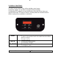
12- DISPLAY FUNCTIONS
The BRICK display panel shows all the available control menus.
Using these options, it is possible to change the fixture’s setting.
Changing the DTS settings can vary the functions of the unit so that it does not
respond to the DMX 512 used to control it. Carefully follow the instructions below
before carrying out any variations or selections.
MENU
To access the control menus in the display panel.
To return to the previous level in the menu structure without
making a change.
To exit the menus.
ENTER
To select any required menu.
To confirm any changes.
UP / DOWN
To navigate the menus structure.
To change any value.
Firmware release
1.00

18
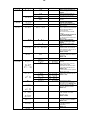
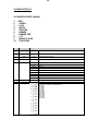
MAIN MENU
LEVEL 1
LEVEL 2
LEVEL 3
FUNCTION
Display normal orientation for
floor mounting position
(Default)
Display inverted orientation for
suspended mounting position
Display always ON (Default)
Display goes OFF after 10
seconds
Allows to select 10 DMX
channels mode (Default)
Allows to select RGBW mode (4
DMX channels)
Allows to select the value of the
delay (in milliseconds) for Dimmer
channel reaction to DMX or
Program variation.
Off = Instant response to DMX
variation.
4 = 100 ms Smooth response to
DMX variation (Default)
20 = 500 ms Smooth response to
DMX variation.
Allows to select Quadratic
current for linear light output
(Default)
Allows to select Linear current
output
Allows to adjust the PWM
frequency value (Hz) in order to
reduce flickering in the process of
your camera recordings.
Default = 610 Hz
Allows to increase the LED’s
current from 1050mA to 1500mA
per channel
Default = ON
Automatic mode without DMX
controller.
Chase with 16 steps previously
created in REC mode.
Speed time and wait time values
(in seconds) selectable by user
(Default = 10).
In Auto mode the unit do generate
DMX for slave units.
16 customizable Colour Macros.
RGBW values selectable by user
(Default = 255).
Rainbow colours effect.
Speed time value (in seconds)
selectable by user (Default = 10).
16 Colour Macros as on DMX
channel 9 (MACRO COLOR).
Default = 01
12 White color temperature from
2700K to 8000K as on DMX
channel 8 (CCT).
Default = 2700K
Dimmer level selectable by user
as on DMX channel 6 (DIMMER)
Default = 255
Shutter level selectable by user
as on DMX channel 5
(SHUTTER)
Default = 15
Esc from automatic mode.

19
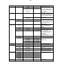
MAIN MENU
LEVEL 1
LEVEL 2
LEVEL 3
FUNCTION
In DMX Recorder mode it is
possible to create and store the
scenes of the CHPR menu by
using an external DMX controller.
The unit must be set to 10 DMX
channels mode.
Refer to “REC MODE” at page 20.
Slave mode.
The unit is forced to DMX address
1 and 10 DMX channels mode
receiving signal from the unit set
in Auto mode.
Esc from slave mode
Allows to select the internal fans
speed.
Standard mode: High fans speed.
Silent mode: Low fans speed for a
very low noise operation.
Default = STD
No DMX action.
Keep last valid DMX signal
(Default)
Black-out
Chase with 16 steps previously
created in REC mode as per
AUTO > CHPR menu.
Speed time and wait time values
(in seconds) selectable by user
(Default = 10).
In Auto mode the unit do generate
DMX for slave units.
All channels @ 100%
Custom.
RGBW values selectable by user
(Default = 255).
To restore default settings
LED temperature monitoring
Micro controller temperature
monitoring
Outputs 1 and 2 of LED Driver
board temperature monitoring
Output 3 and 4 of LED Driver
board temperature monitoring
Shows the total unit life time and
the RGBW LEDs life time
Software version

20
13- REC MODE
DMX Recorder mode
For the programming of ChPr by using a DMX controller, besides the 10 channels necessary
to control the unit a further 3 DMX channels are needed.
So that in RECORDER mode (via DMX) the unit will need 13 channels to be correctly
programmed.
The three new DMX channels are:
DMX channel 11 = SCENES channel
From 0-10 = no function (r001)
From 11-255 are displayed the programmable scenes (max 16 scenes from M001 to M0016)
DMX channel 12 = EDIT channel:
-From 0-19 = no function
-From 20-234 the unit runs the configuration given by the received input DMX values.
With the channel SCENES it is possible to pass from one step to the next while with REC it is
possible to record the selected scene.
-From 235-255 the unit runs the configuration given by the received input DMX values closing
the sequence as last scene.
With the channel REC it is possible to record the selected scene as last scene.
DMX channel 13 = RECORDING channel
Records the set scene with a variation between 0 to 255 (the display flashes indicating that
the scene has been recorded). It is advised that you keep the REC channel set to 0 and to run
through the 255 only once you have decided to save the scene. If ChPr is not closed, by
indicating the last scene (Edit channel between 235-255), in playback mode all 16 scenes will
be played through even if not programmed.
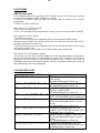
14- ERROR MESSAGES
ERROR SHOWED ON DISPLAY
APPEARS WHEN
LED thermal sensor damaged (open or in
short circuit).
Unit immediately goes in black-out.
LED temperature detected over 100°C.
Unit immediately goes in black-out.
Micro controller thermal sensor damaged
(open or in short circuit).
Unit immediately goes in black-out.
Micro controller temperature detected over
100°C. Unit immediately goes in black-out.
Thermal sensor on outputs 1 and 2 of LED
Driver board damaged (open or in short
circuit).
Unit immediately goes in black-out.
Temperature detected over 100°C on
outputs 1 and 2 of LED Driver board. Unit
immediately goes in black-out.
Thermal sensor on outputs 3 and 4 of LED
Driver board damaged (open or in short
circuit).
Unit immediately goes in black-out.
Temperature detected over 100°C on
outputs 3 and 4 of LED Driver board. Unit
immediately goes in black-out.
La pagina si sta caricando...
La pagina si sta caricando...
La pagina si sta caricando...
La pagina si sta caricando...
La pagina si sta caricando...
La pagina si sta caricando...
La pagina si sta caricando...
La pagina si sta caricando...
La pagina si sta caricando...
La pagina si sta caricando...
La pagina si sta caricando...
La pagina si sta caricando...
-
 1
1
-
 2
2
-
 3
3
-
 4
4
-
 5
5
-
 6
6
-
 7
7
-
 8
8
-
 9
9
-
 10
10
-
 11
11
-
 12
12
-
 13
13
-
 14
14
-
 15
15
-
 16
16
-
 17
17
-
 18
18
-
 19
19
-
 20
20
-
 21
21
-
 22
22
-
 23
23
-
 24
24
-
 25
25
-
 26
26
-
 27
27
-
 28
28
-
 29
29
-
 30
30
-
 31
31
-
 32
32


DTS Brick Manuale utente
- Tipo
- Manuale utente
- Questo manuale è adatto anche per
in altre lingue
- English: DTS Brick User manual
Documenti correlati
-
 DTS X-BRICK Manuale utente
-
 DTS Portfolio Manuale utente
-
 DTS DELTA 12 HEAD Manuale utente
-
 DTS SCENA LED 200 MZ FC Manuale utente
-
 DTS SCENA LED 120 HQS Manuale utente
-
 DTS F-25 Manuale utente
-
 DTS FOS 100 FULL RGBW Manuale utente
-
 DTS FOS 100 SOLO FULL WHITE CT Manuale utente
-
 DTS SCENA LED 80 FR FC Manuale utente
-
 DTS TITAN PLUS SOLO Manuale utente


Altri documenti
-
Vari-Lite VL800 EVENTPAR, WW Guida Rapida
-
Griven Parade L MC 2 Recessed RGBW Manuale del proprietario
-
SGM GENIO MOBILE Manuale utente
-
 Thorn Altis Gen5 / <ALG5 JUNCTION BOX WHITE GB TO 2X1MODULE Guida d'installazione
-
 Tupex HYDROLINE 13-21 PERFORMANCE LED Assembly and Operating Instructions
-
Griven Moon wall Dynamic White Manuale del proprietario
-

