La pagina si sta caricando...

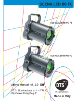
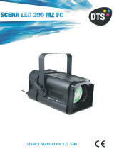
SCENA LED 120 HQS
USER’S MANUAL rel. 1.0 GB

2
Le informazioni contenute in questo documento sono state attentamente redatte e
controllate. Tuttavia non è assunta alcuna responsabilità per eventuali inesattezze.
Tutti i diritti sono riservati e questo documento non può essere copiato, fotocopiato,
riprodotto per intero o in parte senza previo consenso scritto della D.T.S .
D.T.S. si riserva il diritto di apportare senza preavviso cambiamenti e modifiche
estetiche , funzionali o di design a ciascun proprio prodotto. D.T.S non assume alcuna
responsabilità sull’uso o sull’applicazione dei prodotti o dei circuiti descritti.
The information contained in this publication has been carefully prepared and
checked. However, no responsibility will be taken for any errors. All rights are
reserved and this document cannot be copied, photocopied or reproduced, in part or
completely, without prior written consent from D.T.S.
D.T.S. reserves the right to make any aesthetic, functional or design modifications to
any of its products without prior notice. D.T.S. assumes no responsibility for the use or
application of the products or circuits described herein.
Les informations contenues dans le présent manuel ont été rédigées et contrôlées
avec le plus grand soin. Nous déclinons toutefois toute responsabilité en cas
d'éventuelles inexactitudes. Tous droits réservés. Ce document ne peut être copié,
photocopié ou reproduit, dans sa totalité ou partiellement, sans le consentement
préalable de D.T.S.
D.T.S. se réserve le droit d'apporter toutes modifications et améliorations esthétiques,
fonctionnelles ou de design, sans préavis, à chacun de ses produits. D.T.S. décline
toute responsabilité sur l'utilisation ou sur l'application des produits ou des circuits
décrits.
Las informaciones contenidas en este documento han sido cuidadosamente
redactadas y controladas. Con todo, no se asume ninguna responsabilidad por
eventuales inexactitudes. Todos los derechos han sido reservados y este documento
no puede ser copiado, fotocopiado o reproducido, total o parcialmente, sin previa
autorización escrita de D.T.S.
D.T.S. se reserva el derecho a aportar sin previo aviso cambios y modificaciones de
carácter estético, funcional o de diseño a cada producto suyo. D.T.S. no se asume
responsabilidad de ningún tipo sobre la utilización o sobre la aplicación de los
productos o de los circuitos descritos.

3
INDEX:
1- SYMBOLS ................................................................................................................. 4
2- GENERAL WARNING .............................................................................................. 5
3- GENERAL WARRANTY CONDITIONS .................................................................... 5
4- TECHNICAL FEATURES ......................................................................................... 5
5- ACCESSORIES ........................................................................................................ 7
6- IMPORTANT SAFETY INFORMATION .................................................................... 8
6.1 Fire prevention...................................................................................................... 8
6.2 Prevention of electric shock .................................................................................. 8
6.3 Safety ................................................................................................................... 8
6.4 Waste Electrical and Electronic Equipment directive ............................................ 8
7- INSTALLATION ........................................................................................................ 9
8- INPUT / OUTPUT CONNECTIONS ......................................................................... 10
9- DMX SIGNAL CONNECTION ................................................................................. 11
9.1 DMX Addresses .................................................................................................. 12
9.2 Selecting the DMX address ................................................................................ 12
10- RDM FUNCTIONS ................................................................................................ 13
11- FIRMWARE UPDATING ....................................................................................... 18
12- DISPLAY FUNCTIONS ......................................................................................... 19
13- REC MODE ........................................................................................................... 23
14- MANUAL MODE ................................................................................................... 23
15- ERROR MESSAGES ............................................................................................ 24
16- DMX PROTOCOL ................................................................................................. 25

4
!
1- SYMBOLS
Graphic symbols used on this manual:
THIS SYMBOL INDICATES A HOT SURFACE
THIS SYMBOL INDICATES ELECTRIC SHOCK
RISK
THIS SYMBOL INDICATES GENERAL RISK
THIS SYMBOL INDICATES THE MAXIMUM
OPERATING AMBIENT TEMPERATURE
THIS SYMBOL MEANS “DO NOT STARE
AT THE OPERATING LIGHT SOURCE”
THIS SYMBOL INDICATES
PHOTOBIOLOGICAL SAFETY
THIS SYMBOL INDICATES THE EUROPEAN
COMMUNITY DIRECTIVE 2012/19/EC ON
WASTE ELECTRICAL AND ELECTRONIC
EQUIPMENT (WEEE)

5
2- GENERAL WARNING
Read the instruction contained in this user manual carefully, as they give important
information regarding safety during installation, use and maintenance.
The unit is not for household use and must be installed by a qualified electrician or
experienced person.
Always disconnect the device from the mains before maintenance.
The device must always be equipped with an efficient ground connection.
3- GENERAL WARRANTY CONDITIONS
The unit is guaranteed for 36 months from the date of purchase against manufacturing
material defects.
The warranty covers defects in materials and workmanship. The warranty is not
appliable where a defect is caused by misuse or unauthorised repair of the product.
Any functional or/and physical modification of the product is not allowed.
4- TECHNICAL FEATURES
SCENA LED 120 HQS is a compact LED-based projector suitable for all demanding
applications where a perfect color rendition is paramount, such as theatres and TV
studios.
The unit features a high efficiency 120 W 4-color LED source and a 112 mm Fresnel
lens with a long-excursion 20° - 74° linear zoom.
White color temperature can be linearly tuned from 2700K to 8000K.
‘Hi-Q dimming’ technology allows a perfectly smooth fade-in and fade-out at all
dimming levels.
The unit features PowerCon TRUE 1 In/Out panel connectors, and DMX In/Out panel
connectors.
DTS’ HQS (High Quality Spectrum) trademark certifies a projector’ superior white light
quality, and its ability to generate an extended color palette featuring a wide range of
soft shades.
DTS Product code:
03.TS081.46.F SCENA LED 120 FR HQS 5P BLACK
Output
High-power 4-color LED source
LED lifespan: 50.000 hours (70% lumen output)
Optical group
Ø 112 mm Fresnel lens
20° - 74° linear zoom
Color generation
16 million colors
Wide palette of pure uniform whites with variable linear color temperature (2700K –
8000K)

6
Control
DMX 512 / RDM
10 DMX channels (Default)
4-digit 7-segment LED display + 4 soft keys
Internal operating system updatable via DTS Dongle Firmware Uploader
Power supply
Full-range 100-240Vac 50-60 Hz
Power consumption: 120W Max
Connections
Power supply: PowerCON TRUE1 In/Out panel connectors
DMX: XLR 5-pole In/Out panel connectors
Internal safety devices
Overvoltage and overtemperature circuits protection
Operating temperature
-10° / 40°C
Physical
IP20
Weight: 4,5 Kg
Finishing: Black
Certifications

7
DIMENSIONS
5- ACCESSORIES
As standard
1 x Cable with PowerCON TRUE1 female connector (Code 02K0012267.0015)
1 x Filterframe black finishing (already installed on the projector) (Code 02M00422.46)
1 x User’s Manual
Optional (on request)
• Barndoor black finishing (Code 03.TA206)
• “C” Clamp G50 (Max. Load 10 Kg) (Code 0521A012)
• “C” Clamp G60 (Max. Load 50 Kg) (Code 0521A004)
• Safety cable 3 mm x 60 cm, max capacity load 60 Kg (Code 0521A010)
• DTS Dongle firmware uploader (code 03.LA.206)

8
6- IMPORTANT SAFETY INFORMATION
6.1 Fire prevention:
Replace any blown or damaged fuses only with those of identical value: T 2A 250V.
6.2 Prevention from electric shock:
High voltage is present inside the unit. Unplug the unit prior to performing any
operation which involves touching the inside of the unit.
This equipment must be grounded, do not connect to non-grounded supplies.
The use of a thermal magnetic circuit breaker is recommended for each SCENA LED
120 HQS unit.
Use only AC supplies 100-240V 50-60 Hz.
SCENA LED 120 HQS should never be located in position exposed to rain or in areas
of extreme humidity.
A good air ventilation is essential for proper equipment work.
6.3 Safety:
Risk Group 2 product according to EN 62471.
CAUTION. Do not look directly into the light output. May be harmful to the eyes and
skin.
Do not stare at the operating light source.
The luminaire should be positioned so that prolonged staring into the luminaire at a
distance of 6 m is not expected.
The light source contained in this luminaire shall only be replaced by the manufacturer
or his service agent or a similar qualified person.
The unit is not for household use and must be installed by a qualified electrician or
experienced person.
The external surface of the unit may exeed 60°C; never handle the unit until at least 5
minutes have elapsed since the unit was turned off.
Never install the unit in an enclosed area lacking sufficient air flow.
The ambient temperature should not exeed 40°C.
6.4 Waste Electrical and Electronic equipment (WEEE) directive:
The unit, accessories and packaging should be sorted for environmetal-friendly
recycling.
For EC countries: according to the European Directive 2012/19/EC for Waste
Electrical and Electronic Equipment and its implementation into national right,
luminaires that are no longer usable must be collected separately and disposed of in
an environmentally correct manner.
!

9
7- INSTALLATION
The unit is suitable for dry locations only.
SCENA LED 120 HQS can be installed on a truss or on the ceiling.
It is recommended the use of appropriate clamps to fix the unit to the mounting
surface.
ATTENTION:
A safety cable (code 0521A010) must be securely fixed to the unit’s mounting bracket
and to the support structure of the projector as shown in the picture below.
Fixing clamps and safety cable are available on request.

10
8- INPUT / OUTPUT CONNECTIONS
MAINS IN
100-240Vac 50-60 Hz
PowerCON TRUE1
male panel connector
MAINS OUT
100-240Vac 50-60 Hz
MAX 16A
PowerCON TRUE1
female panel connector
Max 20 units @ 230Vac
Max 10 units @ 100Vac
FUSE
T 2A 250V
DISPLAY
PANEL
DMX IN
XLR 5-pole male
panel connector
DMX OUT
XLR 5-pole female
panel connector

11
9- DMX SIGNAL CONNECTION:
The unit operates using a digital DMX 512 signal.
Connection between the controller and the unit or between units must be carried out
using a two pair screened ø 0.5 mm.
Ensure that the conductors do not touch each other.
Do not connect the cable ground to the DMX connector chassis.
The plug housing must be isolated. Connect the mixer signal to the DMX IN projector
plug and connect it to the next projector by connecting the DMX OUT plug on the first
unit to the DMX IN plug of the second one.
In this way, all the projectors are cascade connected.
If the display showing the DMX address flashes, then one of the following errors has
occurred:
- DMX signal not present
- DMX reception problem
For Installations where long distance DMX cable connections are needed, we
suggest to use a DMX terminator.
The DMX terminator is a male XLR 3-5 pins connector with a 120 ohm resistor
Between pin 2 and 3.
The DMX terminator must be plugged into the last unit (DMX out panel connector) of
the DMX line.
PLACE A 120 OHM RESISTOR BETWEEN PIN 2
AND 3 OF A MALE XRL CONNECTOR AND PLUG IT
INTO THE DMX OUT PANEL CONNECTOR OF THE
LAST UNIT CONNECTED TO THE DMX LINE
1
2
3
5
4
OUT
120 ohm
PIN 3
PIN 2

12
9.1 DMX addresses
SCENA LED 120 HQS can be used in 5 DMX modes:
1. 10 channels (Default)
2. RGBA (4 channels)
3. 6 channels
4. FINE (10 channels)
5. PROM (11 channels)
In order to use the unit in 10 DMX channels mode (Default), set the following
addresses on the mixer:
Projector 1 A001
Projector 2 A011 If you want to select the next projector, just add “10”
Projector 3 A021
….. A….
projector 6 A051
9.2 Selecting the DMX address
1) Press the UP-DOWN key until you reach the required DMX address. The numbers
on the display will start to flash (but the new DMX address hasn't yet been set).
2) Press ENTER to confirm your selection. The numbers on the display will stop
flashing and the projector is now controlled by the new DMX address.
TIPS: if you keep pushed the UP or DOWN keys, the channels are calculated more
quickly and you get a faster selection.

13
10- RDM FUNCTIONS
By using a RDM controller it is possible to set DMX address, DMX mode and other
parameters.
SCENA LED 120 HQS accepts the following RDM commands:
RDM Device Model ID: 0x0D6F
RDM PID DESCRIPTION
RDM PID VALUE
GET
SET
Category – Network Management
DISC_UNIQUE_BRANCH
0x0001
DISC_MUTE
0x0002
DISC_UN_MUTE
0x0003
Category – Status Collection
STATUS_MESSAGES
0x0030
X
STATUS_ID_DESCRIPTION
0x0031
X
Category - RDM Information
SUPPORTED_PARAMETERS
0x0050
X
PARAMETERS_DESCRIPTION
0x0051
X
Category – Product Information
DEVICE_INFO
0x0060
X
DEVICE_MODEL_DESCRIPTION
0x0080
X
MANUFACTURER_LABEL
0x0081
X
DEVICE_LABEL
0x0082
X
X
SOFTWARE_VERSION_LABEL
0x00C0
X
Category - DMX512 Setup
DMX_PERSONALITY
0x00E0
X
X
DMX_PERSONALITY_DESCRIPTION
0x00E1
X
DMX_START_ADDRESS
0x00F0
X
X
Category – Sensors
SENSOR_DEFINITION
0x0200
X
SENSOR_VALUE
0x0201
X
X
Category – Power/Lamp Settings
DEVICE_HOURS
0x0400
X
LAMP_HOURS
0x0401
X
Category – Display Settings
DISPLAY_INVERT
0x0500
X
X
Category – Control
IDENTIFY_DEVICE
0x1000
X
Category – Dimmer Settings (Additional Messages)
CURVE
0x0343
X
X
CURVE_DESCRIPTION
0x0344
X
OUTPUT_RESPONSE_TIME
0x0345
X
X
OUTPUT_RESPONSE_TIME_DESCRIPTION
0x0346
X
MODULATION_FREQUENCY
0x0347
X
X
MODULATION_FREQUENCY_DESCRIPTION
0x0348
X

14
10- RDM FUNCTIONS
RDM PID DESCRIPTION
RDM PID VALUE
GET
SET
Category – Manufacturer-Specific PIDs
BOOST
0x9007
X
X
FANS SETTING
0x903A
X
X
DISPLAY STANDBY
0x903C
X
X
NO DMX ACTION
0x9002
X
X
RED NO DMX
0x9003
X
X
GREEN NO DMX
0x9004
X
X
BLUE NO DMX
0x9005
X
X
AMBER NO DMX
0x9006
X
X
INT NO DMX
0x900A
X
X
RED FINE NO DMX
0x9014
X
X
GREEN FINE NO DMX
0x9015
X
X
BLUE FINE NO DMX
0x9016
X
X
AMBER FINE NO DMX
0x9017
X
X
INT FINE NO DMX
0x9018
X
X
RED2 NO DMX
0x9019
X
X
GREEN2 NO DMX
0x901A
X
X
BLUE2 NO DMX
0x901B
X
X
AMBER2 NO DMX
0x901C
X
X
INT2 NO DMX
0x901D
X
X
RED2 FINE NO DMX
0x901E
X
X
GREEN2 FINE NO DMX
0x901F
X
X
BLUE2 FINE NO DMX
0x9020
X
X
AMBER2 FINE NO DMX
0x9021
X
X
INT2 FINE NO DMX
0x9022
X
X
RED3 NO DMX
0x9023
X
X
GREEN3 NO DMX
0x9024
X
X
BLUE3 NO DMX
0x9025
X
X
AMBER3 NO DMX
0x9026
X
X
INT3 NO DMX
0x9027
X
X
RED3 FINE NO DMX
0x9028
X
X
GREEN3 FINE NO DMX
0x9029
X
X
BLUE3 FINE NO DMX
0x902A
X
X
AMBER3 FINE NO DMX
0x902B
X
X
INT3 FINE NO DMX
0x902C
X
X
RED4 NO DMX
0x902D
X
X
GREEN4 NO DMX
0x902E
X
X
BLUE4 NO DMX
0x902F
X
X
AMBER4 NO DMX
0x9030
X
X
INT4 NO DMX
0x9031
X
X
RED4 FINE NO DMX
0x9032
X
X
GREEN4 FINE NO DMX
0x9033
X
X
BLUE4 FINE NO DMX
0x9034
X
X
AMBER4 FINE NO DMX
0x9035
X
X
INT4 FINE NO DMX
0x9036
X
X

15
10- RDM FUNCTIONS
RDM ADDITIONAL MESSAGEs:
CURVE
CURVE DESCRIPTION
1
1: LINEAR
2
2: QUADRATIC (default)
3
3: S-CURVE
4
4: GAMMA 2.2
OUTPUT RESPONSE TIME
OUTPUT_RESPONSE_TIME_DESCRIPTION
0
0: SMOOTH OFF
1
1: SMOOTH 1 ( 25 ms)
2
2: SMOOTH 2 ( 50 ms)
3
3: SMOOTH 3 ( 75 ms)
4
4: SMOOTH 4 (100 ms) (default)
5
5: SMOOTH 5 (125 ms)
6
6: SMOOTH 6 (150 ms)
7
7: SMOOTH 7 (175 ms)
8
8: SMOOTH 8 (200 ms)
9
9: SMOOTH 9 (225 ms)
10
10: SMOOTH 10 (250 ms)
11
11: SMOOTH 11 (275 ms)
12
12: SMOOTH 12 (300 ms)
13
13: SMOOTH 13 (325 ms)
14
14: SMOOTH 14 (350 ms)
15
15: SMOOTH 15 (375 ms)
16
16: SMOOTH 16 (400 ms)
17
17: SMOOTH 17 (425 ms)
18
18: SMOOTH 18 (450 ms)
19
19: SMOOTH 19 (475 ms)
20
20: SMOOTH 20 (500 ms)

16
10- RDM FUNCTIONS
RDM ADDITIONAL MESSAGEs:
MODULATION FREQUENCY
MODULATION FREQUENCY DESCRIPTION
1
1: 610 Hz
2
2: 800 Hz
3
3: 1000 Hz (default)
4
4: 1500 Hz
5
5: 2000 Hz
6
6: 2500 Hz
7
7: 3000 Hz
8
8: 3500 Hz
9
9: 4000 Hz
10
10: 4500 Hz
11
11: 5000 Hz
RDM MANUFACTURER-SPECIFIC PIDs:
MANUFACTURER-SPECIFIC PID
DESCRIPTION
BOOST
0 = Disabled
1 = Enabled (default)
FANS SETTING
0 = Fan mode Standard
1 = Fan mode Silent (default)
DISPLAY STANDBY
0 = OFF (default)
1 = ON
2 = FORCED ON
NO DMX ACTION
1 = BLACKOUT
2 = PROGRAM 1-16
3 = RGB 100%
4 = RGB 60%
5 = CUSTOM
6 = CUSTOM2
7 = CUSTOM3
8 = CUSTOM4
9 = KEEP LAST (default)

17
10- RDM FUNCTIONS
RDM MANUFACTURER-SPECIFIC PIDs:
MANUFACTURER-SPECIFIC PID
DESCRIPTION
RED NO DMX
Range 0-255 (Default = 128)
GREEN NO DMX
Range 0-255 (Default = 128)
BLUE NO DMX
Range 0-255 (Default = 128)
AMBER NO DMX
Range 0-255 (Default = 128)
INT NO DMX
Range 0-255 (Default = 128)
RED FINE NO DMX
Range 0-255 (Default = 128)
GREEN FINE NO DMX
Range 0-255 (Default = 128)
BLUE FINE NO DMX
Range 0-255 (Default = 128)
AMBER FINE NO DMX
Range 0-255 (Default = 128)
INT FINE NO DMX
Range 0-255 (Default = 128)
RED2 NO DMX
Range 0-255 (Default = 128)
GREEN2 NO DMX
Range 0-255 (Default = 128)
BLUE2 NO DMX
Range 0-255 (Default = 128)
AMBER2 NO DMX
Range 0-255 (Default = 128)
INT2 NO DMX
Range 0-255 (Default = 128)
RED2 FINE NO DMX
Range 0-255 (Default = 128)
GREEN2 FINE NO DMX
Range 0-255 (Default = 128)
BLUE2 FINE NO DMX
Range 0-255 (Default = 128)
AMBER2 FINE NO DMX
Range 0-255 (Default = 128)
INT2 FINE NO DMX
Range 0-255 (Default = 128)
RED3 NO DMX
Range 0-255 (Default = 128)
GREEN3 NO DMX
Range 0-255 (Default = 128)
BLUE3 NO DMX
Range 0-255 (Default = 128)
AMBER3 NO DMX
Range 0-255 (Default = 128)
INT3 NO DMX
Range 0-255 (Default = 128)
RED3 FINE NO DMX
Range 0-255 (Default = 128)
GREEN3 FINE NO DMX
Range 0-255 (Default = 128)
BLUE3 FINE NO DMX
Range 0-255 (Default = 128)
AMBER3 FINE NO DMX
Range 0-255 (Default = 128)
INT3 FINE NO DMX
Range 0-255 (Default = 128)
RED4 NO DMX
Range 0-255 (Default = 128)
GREEN4 NO DMX
Range 0-255 (Default = 128)
BLUE4 NO DMX
Range 0-255 (Default = 128)
AMBER4 NO DMX
Range 0-255 (Default = 128)
INT4 NO DMX
Range 0-255 (Default = 128)
RED4 FINE NO DMX
Range 0-255 (Default = 128)
GREEN4 FINE NO DMX
Range 0-255 (Default = 128)
BLUE4 FINE NO DMX
Range 0-255 (Default = 128)
AMBER4 FINE NO DMX
Range 0-255 (Default = 128)
INT4 FINE NO DMX
Range 0-255 (Default = 128)

18
10- RDM FUNCTIONS
RDM STATUS MESSAGE IDs:
Status Message ID
Data Value 1
Data Value 2
Status ID Description
0x801F
ERROR TEMPERATURE LED MODULE
0x8020
ERROR TEMPERATURE LED DRIVER %d
0x8021
ERROR TEMPERATURE MICRO
0x9000
1: RED
2: GREEN
3: BLUE
4: AMBER
ERROR LED %%d OPEN
0x9001
1: RED
2: GREEN
3: BLUE
4: AMBER
ERROR LED %%d SHORT
11- FIRMWARE UPDATING
To update the firmware release of the SCENA LED 120 HQS you need:
- DTS Dongle Firmware Uploader (code 03.LA.206).
- “DTS Firmware Upgrade Utility v.2.02” program installed on PC.
- Latest firmware release available for SCENA LED 120 HQS unit.
Updating the firmware release.
Please follow the procedure below to perform the update:
1. Connect the DTS Dongle Firmware Uploader to a spare USB port on the PC.
2. Connect the unit DMX input to the DTS Dongle Firmware Uploader DMX output with
a standard DMX cable and turn ON the unit.
3. Send the new firmware release into the unit by using “DTS Firmware Upgrade
Utility v.2.02” program. At the end of the procedure, the unit will reset.
For more information please refer to an authorised DTS service centre.

19
12- DISPLAY FUNCTIONS
The SCENA LED 120 HQS display panel shows all the available control menus.
Using these options, it is possible to change the fixture’s setting.
Changing the DTS settings can vary the functions of the unit so that it does not
respond to the DMX 512 used to control it. Carefully follow the instructions below
before carrying out any variations or selections.
MENU
• To access the control menus in the display panel.
• To return to the previous level in the menu structure without
making a change.
• To exit the menus.
ENTER
• To select any required menu.
• To confirm any changes.
UP / DOWN
• To navigate the menus structure.
• To change any value.
FIRMWARE RELEASE
1.00
RDM Device Model ID
0x0D6F
DMX Personality IDs
0x01 “RGBA 10 chans”
0x02 “RGBA 4 chans”
0x03 “RGBA 6 chans”
0x04 “RGBA FINE 10 chans”
0x05 “PROM 11 chans”
DISPLAY KEY-LOCK FUNCTION
Display key-lock function can be enabled/disabled by pressing ENTER + DOWN keys
at the same time for 3 seconds.

20
MAIN MENU
LEVEL 1
LEVEL 2
LEVEL 3
FUNCTION
Display normal orientation for
floor mounting position (Default)
Display inverted orientation for
suspended mounting position
Display stand-by disabled
(Default)
Display goes OFF after 10 seconds
Display forced OFF even if control
signal is missing or error messages
are shown.
Allows to select 10 DMX
channels mode (Default)
Allows to select “RGBA” mode (4
DMX channels).
Allows to select 6 DMX channels
mode.
Allows to select “FINE” mode (10
DMX channels).
Allows to select “PROM” mode (11
DMX channels).
Allows to select the value of the
delay (in milliseconds) for Dimmer
channel reaction to DMX or
Program variation.
Off = Instant response to DMX
variation.
4 = 100 ms Smooth response to
DMX variation (Default)
20 = 500 ms Smooth response to
DMX variation.
Allows to select Quadratic
current output for LED (Default).
Allows to select Linear light output.
Allows to set S-curve to emulates
light intensity characteristics of the
tungsten halogen lamps.
Allows to set gamma curve 2.2 .
Allows to adjust the PWM
frequency value (Hz) in order to
reduce flickering in the process of
your camera recordings.
Range = 610 – 5000 Hz
Default = 1000 Hz
Allows to increase the LED’s
current from 70% to 100%
Default = ON
“COMP” GRAPHICS:
/