
Translation of the original instructions
1 Further applicable documents
All available documents for the product èwww.festo.com/pk.
2 Safety
2.1 Safety instructions
– Take into consideration the ambient conditions at the location of use.
– Only use the product in original status without unauthorised modifications.
– Observe labelling on the product.
– Store the product in a cool, dry, UV-protected and corrosion-protected envir-
onment. Ensure that storage times are kept to a minimum.
– Prior to mounting, installation and maintenance work: Switch off compressed
air supply and secure it from being switched back on.
– Observe tightening torques. Unless otherwise specified, the tolerance
is±20%.
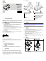
2.2 Intended use
The product is intended for the space-saving transport of masses. A high degree
of positioning accuracy is achieved.
The product is approved for slide operating mode.
Fig. 1
2.3 Training of qualified personnel
Installation, commissioning, maintenance and disassembly should only be con-
ducted by qualified personnel.
The skilled personnel must be familiar with the installation of pneumatic control
systems.
3 Further information
– Accessories èwww.festo.com/catalogue.
– Spare parts èwww.festo.com/spareparts.
4 Service
Contact your regional Festo contact person if you have technical questions
èwww.festo.com.
5 Product overview
5.1 Function
The DGST mini slide is a non-rotating double-piston drive with bearing guide.
When the compressed air supply ports are pressurised reciprocally, the slide
moves back and forth. The DGST-...-E1 is the basic variant with internal elastic
cushioning and without the option of adjusting the stroke. The slide is braked by
external elastic cushioning components in the case of DGST-…-P and by external
hydraulic shock absorbers in the case of DGST-…-Y12. These cushioning compon-
ents also serve to adjust the stroke.
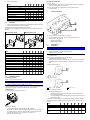
5.2 Design
1
Thread with centring hole for
mounting the payload
2
Centring
3
Thread for mounting the payload
4
Slide
5
Threaded sleeve with cushioning
component:
- Elastic cushioning (P)
- Hydraulic cushioning (Y12)
6
Drill holes for mounting the mini
slide from above (concealed under
the slide)
7
Slot for proximity sensor
8
Thread for mounting the mini-slide
from below (concealed under-
neath)
9
Compressed air supply port
(extending)
10
Compressed air supply port
(retracting)
Fig. 2 Operating elements and connections
6 Transport
NOTICE!
Unexpected and unbraked movement of components
• Secure moving components for transport.
– Take product weight into account è 12 Technical data.
7 Mounting
7.1 Preparation
– Do not modify the screws and threaded pins.
Exception: immediate requirement for change in this instruction manual.
– Place the product in such a way that the operating elements can be reached
(e.g. threaded sleeves for cushioning components).
– Install product without torsional stresses.
– Mount the product to a mounting surface with flatness of 0.05% of the
stroke length, but max. 0.1mm.
– If needed: select mounting components or accessories
èwww.festo.com/catalogue. Centring sleeves are not included in the scope
of delivery.
To prevent collisions, mount the mounting components outside the position-
ing range.
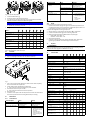
7.2 Mounting
1. Attach drive paying attention to the minimum number of screws.
Direct mounting Through-hole mounting
Tab. 1 Types of mounting
8100367
DGST
Mini slide
8100367
2018-10a
[8100369]
Instructions| Operating
Festo AG & Co. KG
Ruiter Straße 82
73734 Esslingen
Germany
+49 711 347-0
www.festo.com

2. Tighten screws evenly.
DGST-... 6 8 10 12 16 20 25
Minimum number of screws dependent on stroke
10…150 [mm] 2 2 2 2 2 2 2
200 [mm] – 3
Direct mounting
Screw M4 M4 M5 M5 M6 M8 M8
Centring [H7] [mm] 5 5 7 7 9 12 12
Through-hole mounting
Screw M3 M3 M4 M4 M5 M6 M6
Centring [H7] [mm] 5 5 7 7 9 12 12
Tab. 2 Number of screws and screw size
7.3 Attachment
• Fasten the attachment to the slide or the yoke plate with screws and centring
elements. Observe maximum screw-in depthD.
If needed: select mounting components or accessories
èwww.festo.com/catalogue. Centring sleeves are not included in the scope of
delivery.
Mounting with 2 screws Mounting with 4 screws
Tab. 3 Types of mounting
DGST 6 8 10 12 16 20 25
Mounting on the slide (top)
Screw M3 M3 M4 M4 M5 M5 M6
Max. screw-in depth D [mm] 3.1 5.5 4.5 5.2 7.2 8 11
Centring [H7] [mm]
Æ 5 Æ 5 Æ 5 Æ 5 Æ 5 Æ 12 Æ 12
Mounting on the slide with 2 screws (front side)
Screw – M3 M3 M4 M4 M5 M6
Max. screw-in depth D [mm] – 4.7 5.2 6.4 6.4 7.4 7.4
Centring [H7] [mm] –
Æ 5 Æ 5 Æ 7 Æ 7 Æ 12 Æ 12
Mounting on the slide with 4 screws (front side)
Screw M3 M3 M4 M4 M5 M5 M6
Max. screw-in depth D [mm] 4.5 4.5 6.5 6.5 8 8 10
Centring [H7] [mm]
Æ
2H8
Æ 5 Æ 5 Æ 7 Æ 7 Æ 12 Æ 12
Tab. 4 Screw-in depth and screw size
7.4 Mounting accessories
Cushioning components
DGST-...-E1 with internal cushioning:
NOTICE!
When operating the product with internal cushioning, reduce the speed.
• Observe permitted impact energy èTechnical data.
Cushioning components for retrofitting cushioning can be ordered separately and
integrated into the DGST subsequently èwww.festo.com/catalogue.
Proximity sensor
For position sensing with proximity sensors:
Fig. 3 Position sensing
– Slide the proximity sensors 7 into the slots è 5.2 Design.
– Avoid external influence caused by magnetic or ferritic parts in the vicinity of
the proximity sensors. Check the required distance in the application case.
– To avoid contamination: use slot covers on all unused slots
èwww.festo.com/catalogue.
One-way flow control valves
To set the speed:
– Use one-way flow control valves in the supply ports. These are screwed dir-
ectly into the compressed air supply ports.
To secure the payload from dropping when a pressure failure occurs:
– Use check valves.
8 Pneumatic installation
Fig. 4 Supply ports with one-way flow control valves
1. Use one-way flow control valves for setting the speed of the slide.
2. Connect hoses to supply ports:
– 9 Extending movement
– aJ Retracting movement
9 Commissioning
9.1 Preparation
NOTICE!
Unexpected movement of components.
• Keep foreign objects out of the positioning range.
• Initiate start-up at low speed.
– Slowly supply complete system with air. For slow start-up pressurisation, use
on-off valve HEL.
With medium or large payloads and/or at high speeds:
– Use sufficiently large arrester fixtures.
Without the use of external arrester fixtures, the product can contend with the
maximum speeds and payloads defined in catalogue details or in technical
data.
To adjust the end-positions:
1
DGST-...-P
2
DGST-...-Y12
Fig. 5 End position adjustment
– Observe the following points:
– The distance L of the cushioning component must be maintained at a
minimum (factory setting).
– For all adjustment work, all threads of the cushioning component are con-
stantly manipulated.
If the minimum factory setting L is not maintained, the drive will strike internally
(external cushioning not entirely sufficient). This can result in the destruction of
the drive.
DGST-... 6 8 10 12 16 20 25
Distance L at DGST-...-P/-Y12
Retracted end
position
[mm] 2.5 3 3 3 3 3.5 3.5
Extended end
position
[mm] 1.5 2.3 2.4 2.4 2.35 2.25 2.5
Tab. 5 Measure of distance L

Fig. 6 End position adjustment
1. Loosen threaded sleeve5.
2. Position the slide in the desired end position.
3. Turn the internal cushioning component until the end position is reached.
Observe the maximum torque here èFollowing table.
NOTICE!
The exact slide position must be checked during a test run with compressed
air applied and, if necessary, corrected.
4. Retighten the threaded sleeve with the following tightening torque.
DGST-... 6 8 10 12 16 20 25
Threaded sleeve
Internal hexagon
socket
ß 3 4 5 6 8 10 10
Tightening
torque
[Nm] 0.45 0.7 0.9 1.8 2.7 4.5 7
Cushioning component
Internal hexagon
socket DYSS
ß –
1)
2 2 2.5 3 4 5
Internal hexagon
socket DYEF
ß 1.3 1.5 2 2.5 3 4 4
Max. torque [Nm] 0.1 0.5 0.6 1 3 5 10
1) The cushioning component has a slot instead of an internal hexagon socket.
Tab. 6 Internal hexagon socket and torque
9.2 Execution
NOTICE!
Risk of collision by payloads that protrude through the rotor/slide.
• Only turn adjusting screws while the rotor/slide is stationary.
Fig. 7
1. First of all, close the one-way flow control valves on both sides completely,
then unscrew them one complete turn.
2. Initially exhaust drive simultaneously at both sides.
Ä
This causes the slide to move slightly to a point of balance.
3. Then exhaust the drive on just one side.
Ä
This causes the slide to move into an end position.
4. Start the test run.
5. If needed: correct speed at the one-way flow control valves. The slide should
reach the end positions without striking them harshly or recoiling.
10 Malfunctions
10.1 Fault clearance
Fault description Cause Remedy
Slide moves unequally. One-way flow control valves are
not installed correctly.
Control flow of exhaust air, if
possible (not supply air).
Speed is too high. Reduce the speed.The slide strikes the end posi-
tion harshly.
Cushioning is insufficient. – Adjust shock
absorber/fixed stop again
è Preparation for com-
missioning.
– Reduce the speed.
– Check and, if necessary,
replace cushioning com-
ponents.
Fault description Cause Remedy
Missing air cushion. Pressurise both air supply ports
at the same time and then
exhaust at one end.
The shock absorber is faulty. Replace the shock absorber.
The slide strikes the end posi-
tion harshly.
Payload is too great. Reduce payload.
Slide in initial position despite
pressurisation.
Tubing incorrectly connected. Check tubing connection.
The slide speed is too low. Air volume is lacking. – Increase connection cross-
section.
– Check the adjustment of
throttle.
– Connect volume
upstream.
Tab. 7
10.2 Repair
Send the product to the Festo repair service for repair.
– Use the shock absorber paying due regard to environmental protection (use
of problem substances). The shock absorber is filled with hydraulic fluid. Due
to the design, the hydraulic fluid cannot be refilled.
To replace the integrated cushioning components:
1. Observe section on "Adjusting the end positions"è 9.1 Preparation.
2. Loosen the threaded sleeve5 on the cushioning component.
3. Replace cushioning component èwww.festo.com/catalogue:
– DYEF-G8-M_-Y1 at DGST-…-P
– DYSS-G8-…-Y1F at DGST-…-Y12.
4. Adjust the end positions.
5. Lock both cushioning components with the threaded sleeve, observe the
tightening torqueè Tab. 6 Internal hexagon socket and torque.
11 Disposal
ENVIRONMENT!
Send the packaging and product for environmentally sound recycling in accord-
ance with the current regulations èwww.festo.com/sp.
12 Technical data
Size 6 8 10 12 16 20 25
Design Drive with yoke kinematics and
Guide Recirculating ball bearing guide Three-part
cage guide
Mode of operation Double-acting
Pneumatic connection M3 M5 G1/8
Cushioning
– DGST-...-E1 Elastic cushioning, without end-position adjustment, at
both ends
– DGST-...-P Elastic cushioning at both ends, non-adjustable, with
end-position adjustment
– DGST-...-Y12 Shock absorber, self-adjusting on both sides, with end-
position adjustment
Mounting position Any
Max. speed
– DGST-...-E1/Y12 [m/s] 0.5
– DGST-...-P [m/s] 0.5 0.8
Repetition accuracy
– DGST-...-E1/P [mm]
£0.3
– DGST-...-Y12 [mm]
£0.02
Operating medium Compressed air in accordance with ISO8573-1:2010
[7:4:4]
Note on the operating medi-
um
Lubricated operation possible (in which case lubricated
operation will always be required)
Operating pressure
1)
[bar] 1.5…8 1…8
Ambient temperature [°C] –10…+60
Theoretical force at 6 bar
(supply)
[N] 34 60 94 136 241 377 589
Theoretical force at 6 bar
(return)
[N] 25 45 79 102 207 317 495
Impact energy at the end positions
– DGST-...-E1 [J] 0.005 0.03 0.05 0.07 0.15 0.2 0.3
– DGST-...-P [J] 0.018 0.05 0.08 0.12 0.25 0.35 0.45
– DGST-...-Y12 (per
stroke)
[J] 0.09 0.18 0.28 0.48 0.85 1.9 3.6
Max. operating frequency at
DGST-...-Y12
[Cycles/-
min]
50 80 80 80 70 50 50
Product weight at 10 mm
stroke with DGST-...-E1
[g] 90 129 247 391 454 978 1463
Product weight at max.
stroke with DGST-...-E1
[g] 172 310 561 988 1402 3275 4803

Size 6 8 10 12 16 20 25
Materials
Slide, housing Anodised wrought aluminium alloy
Piston rod High-alloy stainless steel
Guide High-alloy steel, POM, TPE
Seals HNBR/PU
1)
For sizes 6/8/10/12, the min. operating pressure can be easily increased after a rest period > 24 h.
Tab. 8 Technical data DGST
-
 1
1
-
 2
2
-
 3
3
-
 4
4


in altre lingue
- English: Festo DGST-8 Operating instructions
Documenti correlati
Altri documenti
-
AVENTICS MSC-12 Manuale del proprietario
-
Danfoss Differential pressure switch, types RT 260A, RT 262A, RT 265A, RT 260AL, RT 262AL, RT 263AL, RT 266AL Guida d'installazione
-
Groupe Brandt DTE1158X Manuale del proprietario
-
-
Asco Series 448 Rodless Band Cylinders STB STBB STBN Manuale del proprietario
-
-