
8107301
DACS-...-S; DFLC/DFLG-...-S
Holding brake; Cylinder with holding brake
8107301
2019-07
[8107303]
Instructions| Operat-
ing

Translation of the original instructions
2 Festo — DACS-...-S; DFLC/DFLG-...-S — 2019-07

3Festo — DACS-...-S; DFLC/DFLG-...-S — 2019-07
1 About this document................................................................................................... 5
1.1 Applicable documents.................................................................................................. 5
1.2 Specified standards...................................................................................................... 5
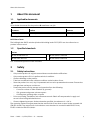
2 Safety........................................................................................................................... 5
2.1 Safety instructions........................................................................................................ 5
2.2 Intended use................................................................................................................ 6
2.3 Foreseeable misuse...................................................................................................... 6
2.4 Training of qualified personnel..................................................................................... 6
3 Information on functional safety................................................................................. 7
3.1 Achievable safety rating............................................................................................... 7
3.2 Safety functions............................................................................................................ 7
3.3 Operating conditions.................................................................................................... 7
3.4 Limitations of use......................................................................................................... 7
3.5 Safety parameters according to EN ISO 13849-1.......................................................... 7
3.5.1 Service life.............................................................................................................. 7
3.5.2 Safety function 1.....................................................................................................8
3.5.3 Safety function 2.....................................................................................................11
4 Further information..................................................................................................... 12
5 Service..........................................................................................................................12
6 Product overview......................................................................................................... 12
6.1 Function....................................................................................................................... 12
6.2 Structure...................................................................................................................... 13
7 Transport..................................................................................................................... 15
8 Mounting..................................................................................................................... 15
8.1 Assembly...................................................................................................................... 15
8.1.1 Mounting the holding brake on the existing cylinder.............................................. 15
8.1.2 Mounting the holding brake on round material.......................................................17
8.2 Installation................................................................................................................... 18
8.2.1 Horizontal installation of the cylinder with holding brake....................................... 18
8.2.2 Vertical installation of the cylinder with holding brake........................................... 20
8.3 Mounting the attachment component.......................................................................... 21
8.4 Mounting the accessories............................................................................................. 21
9 Installation.................................................................................................................. 22
10 Commissioning............................................................................................................ 23
10.1 Test run......................................................................................................................... 23
10.2 Functional tests............................................................................................................ 24
10.2.1 Test for horizontal mounting position without additional weight force................... 25
10.2.2 Test for vertical mounting position with additional weight force hanging............... 27
10.2.3 Test for vertical mounting position with additional weight, standing orientation....29
11 Operation..................................................................................................................... 31
Table of contents

12 Maintenance.................................................................................................................31
13 Malfunctions................................................................................................................ 33
13.1 Fault clearance.............................................................................................................. 33
13.2 Repair............................................................................................................................34
14 Disassembly.................................................................................................................34
15 Disposal........................................................................................................................34
16 Technical data.............................................................................................................. 34
4 Festo — DACS-...-S; DFLC/DFLG-...-S — 2019-07

5Festo — DACS-...-S; DFLC/DFLG-...-S — 2019-07
1 About this document
1.1 Applicable documents
All available documents for the product èwww.festo.com/pk.
Document Product Contents
Instructions Proximity sensor DADG-D-F8 Assembly
Tab. 1 Applicable documents
Definition of term
The holding brakeDACS and the cylinder with holding brakeDFLC/DFLG are also referred to as
product in this manual.
1.2 Specified standards
Version
EN ISO 12100:2011-03 EN ISO 13849-1:2016-06
EN ISO 4414:2011-04 EN ISO 13849-2:2012-10
Tab. 2 Standards specified in the document
2 Safety
2.1 Safety instructions
– Only use the product in original status without unauthorised modifications.
– Only use the product if it is in perfect technical condition.
– Observe labelling on the product.
– Take into consideration the ambient conditions at the location of use.
– Store the product in a cool, dry, UV-protected and corrosion-protected environment. Ensure that
storage times are kept to a minimum.
– Protect the product during storage and operation from the following:
– Corrosive coolant or other materials (e.g. ozone)
– Oils, greases and grease-solvent vapours
– Grinding dust, glowing chips or sparks
– Prior to mounting, installation and maintenance work: Switch off compressed air supply and
secure it from being switched back on.
– Observe tightening torques. Unless otherwise specified, the tolerance is±20%.
The operating modes must guarantee that the residual risk is less than or equal to the accepted risk
(EN ISO 12100). The measures for risk reduction are to be taken in accordance with EN ISO 4414,
EN ISO 12100 and EN ISO 13849-1.
About this document

Monitor/check the function of the entire system during use in accordance with the measures defined
in the validation report ( EN ISO 13849-2).
2.2 Intended use
The products are intended for installation in machines or automated systems and may be used only in
the following ways:
– In the industrial sector without substances and ambient conditions that influence the materials
used or the function
– In its original condition, without unauthorised modifications
– In perfect technical condition
The holding brake DACS and the cylinder with holding brake DFLC/DFLG are designed for the following
applications:
– Retaining a piston rod by clamping with frictional locking
– Stopping the movement of a piston rod by clamping with frictional locking
The holding brake must be checked regularly è 12 Maintenance:
– Depending on the number of actuations, the holding brake and the piston rod must be checked for
function and signs of wear at specified intervals.
– When using the holding brake to stop a movement:
After every shutdown, the holding brake including mounting and piston rod must also be checked
for function, signs of wear and damage.
2.3 Foreseeable misuse
Foreseeable misuse includes:
– Outdoor use
– Use in oily or heavily polluted environments
– Bypassing of safety functions
– Positioning tasks
– Transmission of torques or transverse forces
2.4 Training of qualified personnel
Installation, commissioning, maintenance and disassembly should only be conducted by qualified per-
sonnel.
The skilled personnel must be familiar with the installation of pneumatic control systems.
Safety
6 Festo — DACS-...-S; DFLC/DFLG-...-S — 2019-07

3 Information on functional safety
3.1 Achievable safety rating
The products are intended for use in accordance with ENISO13849-1 as an element in a safety-
related system up to category 1, Performance Level (PL)c.
For use in safety-related systems from category 2 onwards, additional measures are required which
must be determined depending on the application.
It is only possible to determine whether the product is suitable for specific applications by also
assessing further components of the subsystem.
3.2 Safety functions
The products have the following safety functions:
– Safety function 1: retaining a piston rod by clamping with frictional locking
– Safety function 2: stopping the movement of a piston rod by clamping with frictional locking
The safety functions are triggered by switching off the compressed air supply or by the failure of the
compressed air supply.
3.3 Operating conditions
– General information on safe operation è 2 Safety
– Ambient conditions and additional technical specifications è 16 Technical data.
3.4 Limitations of use
The operating life is limited to the service life parameter B
10D
and to the operating life T
M
è 3.5 Safety parameters according to EN ISO 13849-1 as the maximum.
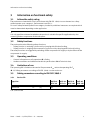
3.5 Safety parameters according to EN ISO 13849-1
3.5.1 Service life
Type/size DACS-16
DFLC-40
DACS-20
DFLC-63
DACS-25
DFLC-100
DACS-40
DFLG-160
Service life T
M
[a] 20
Tab. 3 Service life
Information on functional safety
7Festo — DACS-...-S; DFLC/DFLG-...-S — 2019-07

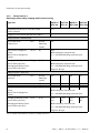
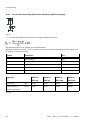
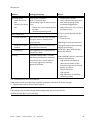
3.5.2 Safety function 1
Retaining a piston rod by clamping with frictional locking
Type/size DACS-16
DFLC-40
DACS-20
DFLC-63
DACS-25
DFLC-100
DACS-40
DFLG-160
Performance level (PL) in accordance with
ENISO13849-1
PLc
Category in accordance with ENISO13849-1 1
Safety function 1 without load
Service life value
without load
B
10D
[million
switching
cycles]
2.0
Mean time to dangerous
failure
(Mean Time to dangerous
Failure)
MTTF
D
[a] 200
With exemplary actuation rate
n
op
= 100 000 switching cycles per year
0.57 × 10
-6
With exemplary actuation rate
n
op
= 100 000 switching cycles per year
Average probability of dan-
gerous failure per hour
(Average probability of dan-
gerous failure per hour)
PFH
D
[1/h]
Diagram: è Fig.1
Safety function 1 with load
Service life value
with load
B
10D
[million
switching
cycles]
1.0 1.0 0.9 0.7
Load/test force [N] 754 1870 4712 12064
100 100 90 70Mean time to dangerous
failure
(Mean Time to dangerous
Failure)
MTTF
D
[a]
With exemplary actuation rate
n
op
= 100 000 switching cycles per year
1.14 ×
10
-6
1.14 ×
10
-6
1.27 ×
10
-6
1.63 ×
10
-6
With exemplary actuation rate
n
op
= 100 000 switching cycles per year
Average probability of dan-
gerous failure per hour
(Average probability of dan-
gerous failure per hour)
PFH
D
[1/h]
Diagram: è Fig.2
Tab. 4 Safety characteristic values for safety function 1
Information on functional safety
8 Festo — DACS-...-S; DFLC/DFLG-...-S — 2019-07

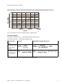
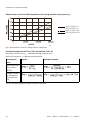
Safety function 1 without load: PFH
D
dependent on the average actuation rate per year (n
op
)
Fig. 1 Characteristic curve for safety function 1 without load
Calculation example
Exemplary actuation rate n
op
= 100 000 switching cycles per year
Service life value B
10D
= 2 000 000 switching cycles
Characteristic
value
Formula Calculation example with result
Mean time to dan-
gerous failure
(MTTF
D
)
Average probabil-
ity of dangerous
failure per hour
PFH
D
Tab. 5 Calculation example of safety function 1 without load
Information on functional safety
9Festo — DACS-...-S; DFLC/DFLG-...-S — 2019-07

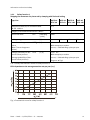
Safety function 1 with load: PFH
D
dependent on the average actuation rate per year (n
op
)
DACS-25/DFLC-100
DACS-40/DFLG-160
DACS-16/DFLC-40
DACS-20/DFLC-63
Fig. 2 Characteristic curves for safety function 1 with load
Calculation example for DACS-16 / DFLC-40; DACS-20 / DFLC-63
Exemplary actuation rate n
op
= 100 000 switching cycles per year
Service life value B
10D
= 1 000 000 switching cycles
Characteristic
value
Formula Calculation example
Mean time to dan-
gerous failure
(MTTF
D
)
Average probabil-
ity of dangerous
failure per hour
PFH
D
Tab. 6 Calculation example of safety function 1 with load
Information on functional safety
10 Festo — DACS-...-S; DFLC/DFLG-...-S — 2019-07

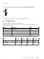
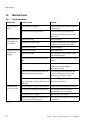
3.5.3 Safety function 2
Stopping the movement of a piston rod by clamping with frictional locking
Type/size DACS-16
DFLC-40
DACS-20
DFLC-63
DACS-25
DFLC-100
DACS-40
DFLG-160
Performance level (PL) in accordance with
ENISO13849-1
PLc
Category in accordance with ENISO13849-1 1
Service life value B
10D
[switching
cycles]
2000
Braking energy [J] 44 123 230 770
Mean time to dangerous
failure
(Mean Time to dangerous
Failure)
MTTF
D
[a] 100
With exemplary actuation
rate n
op
= 200 switching cycles per year
1.14 × 10
-6
With exemplary actuation
rate n
op
= 200 switching cycles per year
Average probability of dan-
gerous failure per hour
(Average probability of dan-
gerous failure per hour)
PFH
D
[1/h]
Diagram: è Fig.3
Tab. 7 Safety characteristic values for safety function 2
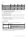
PFH
D
dependent on the average actuation rate per year (n
op
)
Fig. 3 Characteristic curve for safety function 2
Information on functional safety
11Festo — DACS-...-S; DFLC/DFLG-...-S — 2019-07

Calculation example
Exemplary actuation rate n
op
= 200 switching cycles per year
Service life value B
10D
= 2 000 switching cycles
Characteristic
value
Formula Calculation example
Mean time to dan-
gerous failure
(MTTF
D
)
Average probabil-
ity of dangerous
failure per hour
PFH
D
Tab. 8 Calculation example safety function 2
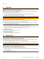
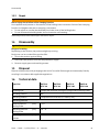
4 Further information
– Accessories èwww.festo.com/catalogue.
– Spare parts èwww.festo.com/spareparts.
5 Service
Contact your regional Festo contact person if you have technical questions èwww.festo.com.
6 Product overview
6.1 Function
Function of the holding brake DACS
The holding of a piston rod and the stopping of the movement of a piston rod is effected by a pre-
loaded spring assembly which acts on the internal clamping collet.
In the event of exhausting or compressed air failure, the spring-loaded clamping collet causes the pis-
ton rod used by the customer or the round material to be blocked.
The spring-loaded system guarantees the fail-safe principle.
Releasing the clamp:
When compressed air is applied to the supply port, the clamping collet is opened by the pneumatically
driven release mechanism.
The piston rod / round material can then move freely in both axial directions.
For safety reasons, no readjustment or manual unlocking of the clamping collet is provided.
Function of the cylinder with holding brake DFLC/DFLG
The function of the cylinder with holding brake DFLC/DFLG corresponds to that of the holding brake
DACS.
In the cylinder with holding brake DFLC/DFLG, the holding brake is connected to a double-acting pneu-
matic cylinder and the spring-loaded clamping collet acts on the piston rod of the cylinder.
Further information
12 Festo — DACS-...-S; DFLC/DFLG-...-S — 2019-07

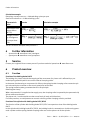
6.2 Structure
Holding brake DACS
1
Supply port
2
Plug screw (connection of the optional prox-
imity sensor DADG-D-F8)
3
Adapter flange
4
Tie rod (4x); attention! Do not loosen tie rod
fastening.
5
Cover
6
Threaded pin (4x); attention! Do not adjust
the internal threaded pin. Do not use thread
for retaining screw.
7
Scraper and seal (for piston rod or round
material)
8
Threaded hole (4x) for retaining screw
Fig. 4 Structure (shown DACS-20-A-S)
Product overview
13Festo — DACS-...-S; DFLC/DFLG-...-S — 2019-07

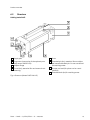
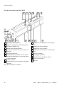
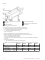
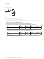
Cylinder with holding brake DFLC/DFLG
1
Supply port (holding brake)
2
Plug screw (connection of the optional prox-
imity sensor DADG-D-F8)
3
Adapter flange (holding brake)
4
Tie rod (4x); attention! Do not loosen tie rod
fastening.
5
Cover (holding brake)
6
Threaded pin (4x); attention: do not adjust
the internal threaded pin. Do not use thread
for retaining screw.
7
Scraper and seal
8
Threaded hole (4x) for retaining screw (hold-
ing brake)
9
Adjustment of end-position cushioning in
front
10
Supply port, front (cylinder)
11
Supply port, rear (cylinder)
12
Adjustment of end-position cushioning at
rear
13
End cap (cylinder)
14
Bearing cap (cylinder)
15
Nuts (4x) for mounting the cylinder
16
Piston rod (cylinder)
17
Hex nut
Fig. 5 Structure (DFLC-63 shown)
Product overview
14 Festo — DACS-...-S; DFLC/DFLG-...-S — 2019-07

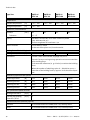
7 Transport
CAUTION!
Danger of crushing
Depending on the version, the product weighs up to 50kg.
Body parts can be crushed if the product falls.
• Secure the product against falling.
• Take product weight into account è 16 Technical data.
8 Mounting
8.1 Assembly
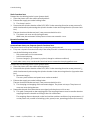
8.1.1 Mounting the holding brake on the existing cylinder
WARNING!
Risk of injury due to failure of the clamping function.
Unacceptable readjustment or disassembly of the holding brake can lead to failure of the clamping
function and lengthen the path to stopping a movement.
• Do not adjust or unscrew the threaded pins in the cover of the holding brake.
• Do not disassemble holding brake; do not loosen tie rod fastening.
CAUTION!
Danger of crushing
Depending on the version, the product weighs up to 50kg.
Body parts can be crushed if the product falls.
• Secure the product against falling.
Transport
15Festo — DACS-...-S; DFLC/DFLG-...-S — 2019-07

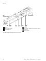
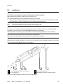
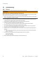
1
Cylinder
2
Bearing cap (cylinder)
3
Threaded pin (4x)
4
Nut (4x)
5
Tie rod (4x); attention! Do not loosen tie rod
fastening.
6
Holding brake
Fig. 6 Mounting the holding brake on the cylinder
Mounting
16 Festo — DACS-...-S; DFLC/DFLG-...-S — 2019-07

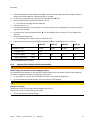
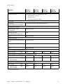
1. Screw threaded pins with sufficient strength class into the bearing cap of the cylinder. Observe
table specifications è Tab. 9 Holding brake on cylinder.
2. Connect the compressed air supply to the holding brake è Fig.4.
3. Pressurise the holding brake with at least 3.8bar.
Ä
The internal clamping collet is released.
4. Clean the piston rod.
5. Push the holding brake over the piston rod of the cylinder up to the gap-free contact on the bear-
ing cap of the cylinder.
6. Screw the nuts onto the threaded pins è Tab. 9 Holding brake on cylinder. Do not tighten the
nuts yet.
7. Exhaust the holding brake.
Ä
The holding brake centres itself on the piston rod.
8. Tighten the nuts to the specified tightening torque è Tab. 9 Holding brake on cylinder.
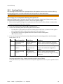
Size DACS-16 DACS-20 DACS-25 DACS-40
Threaded pin/nut 4x M6 4x M8 4x M10 4x M16
– Strength class ³ 8.8
– Screw-in depth [mm] ³ 16 ³ 16 ³ 17 ³ 24
– Tightening torque [Nm] 4 6 15 80
Tab. 9 Holding brake on cylinder
8.1.2 Mounting the holding brake on round material
WARNING!
Risk of injury due to failure of the clamping function.
Unacceptable readjustment or disassembly of the holding brake can lead to failure of the clamping
function and lengthen the path to stopping a movement.
• Do not adjust or unscrew the threaded pins in the cover of the holding brake.
• Do not disassemble holding brake; do not loosen tie rod fastening.
CAUTION!
Danger of crushing
Depending on the version, the product weighs up to 50kg.
Body parts can be crushed if the product falls.
• Secure the product against falling.
Mounting
17Festo — DACS-...-S; DFLC/DFLG-...-S — 2019-07

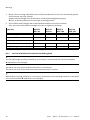
1
Tie rod (4x); attention! Do not loosen tie rod
fastening.
2
Cover (holding brake)
3
Round material (with bevel)
4
Threaded hole (4x) for retaining screw
5
Holding brake
Fig. 7 Holding brake on round material
1. Observe specifications for round material è 16 Technical data.
2. Connect the compressed air supply to the holding brake è Fig.4.
3. Pressurise the holding brake with at least 3.8bar.
Ä
The internal clamping collet is released.
4. Clean round material.
5. Push the holding brake over the chamfered end of the round material.
6. Select screws with sufficient strength class. Observe maximum screw-in depth
è Tab. 10 Holding brake on round material.
Further mounting options è 8.2 Installation.
7. Screw the screws into the threaded holes4 in the cover of the holding brake. Do not tighten
screws yet.
8. Exhaust the holding brake.
Ä
The holding brake centres itself on the round material.
9. Tighten screws to the specified tightening torque è Tab. 10 Holding brake on round material.
Size DACS-16 DACS-20 DACS-25 DACS-40
Screw 4x M6 4x M8 4x M10 4x M16
– Strength class ³ 8.8
– Screw-in depth [mm] £ 13 £ 14.5 £ 14.5 £ 21
– Tightening torque [Nm] 5 8 15 105
Tab. 10 Holding brake on round material
Mounting
18 Festo — DACS-...-S; DFLC/DFLG-...-S — 2019-07

8.2 Installation
Permissible mounting when using the holding brake to stop movements
When stopping movements, higher forces and loads arise:
The fastening elements must be suitable for the forces occurring.
• Only mount the holding brake directly on the machine frame or install it with the flange mounting
FNC/FNG è 8.2.2 Vertical installation of the cylinder with holding brake.
8.2.1 Horizontal installation of the cylinder with holding brake
For horizontal installation when using the holding brake for holding, the foot mounting HNC/HNG
available as an accessory is recommendedèwww.festo.com/catalogue.
The HNC/HNG foot mounting is not approved for use with the holding brake to stop movements.
The piston rod may only be loaded in the direction of movement.
The piston rod must not be used to transmit transverse forces or torques.
With the flexo coupling available as an accessory, transverse forces or bending moments on the piston
rod can be prevented èwww.festo.com/catalogue.
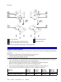
1
Foot mounting HNC/HNG (accessories)
2
End cap (cylinder)
3
Cover (holding brake)
4
Threaded hole (4x) for retaining screw
Fig. 8 Horizontal installation with foot mounting HNC/HNG
Mounting
19Festo — DACS-...-S; DFLC/DFLG-...-S — 2019-07

1. Mount a foot mountingHNC/HNG to each of the threaded holes in the cover of the holding brake
and in the end cap of the cylinder.
Please note the strength class of the screws, screw depth and tightening torque
è Tab. 11 Mounting elements for horizontal mounting position.
2. Place cylinder with holding brake at the intended installation location and fasten.
Only use screws with sufficient strength class (8.8 or higher) for fastening.
Type/size DACS-16
DFLC-40
DACS-20
DFLC-63
DACS-25
DFLC-100
DACS-40
DFLG-160
Foot mounting (accessories) HNC-40 HNC-63 HNC-100 HNG-160
Screw 4x M6 4x M8 4x M10 4x M16
– Strength class ³ 8.8
– Screw-in depth [mm] 8.5…13 9.5…14 10.5…14.5 14.5…21
– Tightening torque [Nm] 5 8 15 105
Tab. 11 Mounting elements for horizontal mounting position
8.2.2 Vertical installation of the cylinder with holding brake
The FNC/FNG flange mounting available as an accessory is recommended for vertical installation
èwww.festo.com/catalogue.
The piston rod may only be loaded in the direction of movement.
The piston rod must not be used to transmit transverse forces or torques.
With the flexo coupling available as an accessory, transverse forces or bending moments on the piston
rod can be prevented èwww.festo.com/catalogue.
Mounting
20 Festo — DACS-...-S; DFLC/DFLG-...-S — 2019-07
La pagina si sta caricando...
La pagina si sta caricando...
La pagina si sta caricando...
La pagina si sta caricando...
La pagina si sta caricando...
La pagina si sta caricando...
La pagina si sta caricando...
La pagina si sta caricando...
La pagina si sta caricando...
La pagina si sta caricando...
La pagina si sta caricando...
La pagina si sta caricando...
La pagina si sta caricando...
La pagina si sta caricando...
La pagina si sta caricando...
La pagina si sta caricando...
La pagina si sta caricando...
La pagina si sta caricando...
-
 1
1
-
 2
2
-
 3
3
-
 4
4
-
 5
5
-
 6
6
-
 7
7
-
 8
8
-
 9
9
-
 10
10
-
 11
11
-
 12
12
-
 13
13
-
 14
14
-
 15
15
-
 16
16
-
 17
17
-
 18
18
-
 19
19
-
 20
20
-
 21
21
-
 22
22
-
 23
23
-
 24
24
-
 25
25
-
 26
26
-
 27
27
-
 28
28
-
 29
29
-
 30
30
-
 31
31
-
 32
32
-
 33
33
-
 34
34
-
 35
35
-
 36
36
-
 37
37
-
 38
38


in altre lingue
- English: Festo 8072774
Documenti correlati
-
Festo DYSS Manuale utente
-
Festo PAML-90 Series Istruzioni per l'uso
-
-
-
-
-
Festo 1451384 Operating Instructions Manual
-
