Immergas Victrix TT Series Manuale utente
- Tipo
- Manuale utente

Instruction and
warning book IE
IT
Istruzioni e avvertenze
COD. 3.017324
KIT ANTIGELO
Victrix Serie TT - Plus ErP
Magis Pro - Magis Pro V2
Magis Combo - Plus
Magis Combo - Plus V2
Victrix Exa
Victrix Tera - Plus
Victrix Hybrid - Plus
Victrix Tera Vip
Intec Combi Internal / External
Intec System Internal / External
Victrix Omnia
Trio Pack
Victrix Superior - Plus
ANTIFREEZE KIT
Victrix TT Series - Plus ErP
Magis Pro - Magis Pro V2
Magis Combo - Plus
Magis Combo - Plus V2
Victrix Exa
Victrix Tera - Plus
Victrix Hybrid - Plus
Victrix Tera Vip
Intec Combi Internal / External
Intec System Internal / External
Victrix Omnia
Trio Pack
Victrix Superior - Plus

2
INDEX
General warnings. ....................................................................................................3
Technical data. ..........................................................................................................3
Instructions for the installer. ...................................................................................3
Victrix TT Plus series - Victrix Tera Plus - Victrix Hybrid Plus models ..........3
Victrix TT Series - Victrix Tera - Victrix Tera Vip - Victrix Hybrid Models. ..5
Victrix Omnia (DIN coupling). ..............................................................................7
Victrix Omnia (Immergas template coupling). ....................................................9
Victrix Omnia (container). ...................................................................................11
Magis Pro - Magis Pro V2. ....................................................................................13
Victrix EXA, Intec Combi Internal / External, Intec System Internal /
External Models. .....................................................................................................14
Magis Combo - Magis Combo V2 .......................................................................15
Magis Combo Plus - Magis Combo Plus V2 ......................................................16
Trio Pack. .................................................................................................................17
Victrix Superior - Victrix Superior Plus .............................................................19
Final operations .....................................................................................................20
Warnings for the technician ..................................................................................20
SOMMARIO
Avvertenze generali ..................................................................................................3
Dati tecnici ................................................................................................................3
Istruzioni per l'installatore ......................................................................................3
Modelli Victrix serie TT Plus - Victrix Tera Plus - Victrix Hybrid Plus ...........4
Modelli Victrix serie TT - Victrix Tera - Victrix Tera Vip - Victrix Hybrid ....6
Victrix Omnia (attacco DIN) ..................................................................................8
Victrix Omnia (attacco Dima Immergas) ...........................................................10
Victrix Omnia (incasso) ........................................................................................12
Magis Pro - Magis Pro V2 .....................................................................................13
Modelli Victrix EXA, Intec Combi Internal / External, Intec System Internal
/ External .................................................................................................................14
Magis Combo - Magis Combo V2 .......................................................................15
Magis Combo Plus - Magis Combo Plus V2 ......................................................16
Trio Pack ..................................................................................................................17
Victrix Superior - Victrix Superior Plus ..............................................................18
Operazioni nali .....................................................................................................20
Avvertenze per il tecnico .......................................................................................20

3
Avvertenze generali
Tutti i prodotti Immergas sono protetti con idoneo imballaggio da trasporto.
Il materiale deve essere immagazzinato in ambienti asciutti ed al riparo dalle
intemperie.
Il presente foglio istruzioni contiene informazioni tecniche relative all’installazione
del kit Immergas. Per quanto concerne le altre tematiche correlate all’installazione
del kit stesso (a titolo esemplicativo: sicurezza sui luoghi di lavoro, salvaguardia
dell’ambiente, prevenzioni degli infortuni), è necessario rispettare i dettami della
normativa vigente ed i principi della buona tecnica.
L’installazione o il montaggio improprio dell’apparecchio e/o dei componenti,
accessori, kit e dispositivi Immergas potrebbe dare luogo a problematiche non
prevedibili a priori nei confronti di persone, animali, cose. Leggere attentamente
le istruzioni a corredo del prodotto per una corretta installazione dello stesso.
L'installazione e la manutenzione devono essere eettuate in ottemperanza alle
normative vigenti, secondo le istruzioni del costruttore e da parte di personale
abilitato nonché professionalmente qualicato, intendendo per tale quello avente
specica competenza tecnica nel settore degli impianti, come previsto dalla Legge
DATI TECNICI
Cavo scaldante 230 V 50 W
Termostato clicson
Temperatura di apertura 14°C (+/- 3°C)
Temperatura di chiusura 4°C (+/- 3°C)
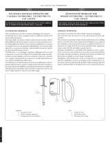
ISTRUZIONI PER L'INSTALLATORE
Per eettuare il montaggio del Kit antigelo procedere nel seguente modo:
Togliere tensione all'apparecchio disalimentando l'interruttore a monte
della caldaia.
Smontare la mantellatura (vedi Libretto istruzioni caldaia) e procedere all'in-
stallazione del kit seguendo le istruzioni riferite al proprio modello di caldaia.
Assicuratevi che la potenza elettrica disponibile e la frequenza della rete siano
adatte al corretto funzionamento del dispositivo, tenuto conto delle condizioni
speciche dell’ubicazione, e che la potenza sia suciente per alimentare qualsiasi
altro apparecchio collegato allo stesso circuito.
L’apparecchio deve essere collegato alla terra per evitare gli eventuali pericoli
risultanti dai difetti di isolamento.
Tutti gli interventi sugli elementi elettrici dell’apparecchio sono vietati in pre-
senza di acqua e di umidità.
Il presente foglio è da lasciare all'utente abbinato al libretto istruzioni
del generatore
IT
General warnings
All Immergas products are protected with suitable transport packaging.
e material must be stored in a dry place protected from the weather.
is instruction manual provides technical information for installing the Immergas
kit. As for the other issues related to kit installation (e.g. safety in the workplace,
environmental protection, accident prevention), it is necessary to comply with
the provisions specied in the regulations in force and with the principles of good
practice.
Improper installation or assembly of the Immergas appliance and/or components,
accessories, kits and devices can cause unexpected problems for people, animals
and objects. Read the instructions provided with the product carefully to ensure
proper installation.
Installation and maintenance must be performed in compliance with the regula-
tions in force, according to the manufacturer's instructions and by professionally
qualied sta, meaning sta with specic technical skills in the plant sector, as
envisioned by the law.
TECHNICAL DATA
Heating cable 230 V 50 W
Klixon thermostat
Opening temperature 14°C (+/- 3°C)
Closing temperature 4°C (+/- 3°C)
INSTRUCTIONS FOR THE INSTALLER
Proceed as follows to assemble the antifreeze kit:
Cut power to the appliance by disconnecting the switch upstream from the
boiler.
Disassemble the casing (see the boiler instructions manual) and install the kit,
following the instructions for your boiler model.
Ensure that the net available power and frequency are appropriate for the
correct device operation. Bear in mind the specic position conditions and
ensure that there is enough power to supply any other appliance connected to
the same circuit.
e appliance must be grounded to prevent danger caused by insulation defects.
All interventions on appliance electric elements are prohibited in the presence
of water and humidity.
is sheet must be le with the user along with the generator
instructions manual
IE

4
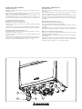
MODELLI VICTRIX SERIE TT PLUS VICTRIX TERA
PLUS VICTRIX HYBRID PLUS
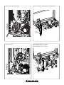
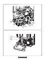
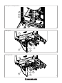
Montaggio cavo scaldante interno caldaia (Fig. 1 - 3)
Invertire l'orientamento del pressacavo (3) sul cavo scaldante (2).
Eliminare il tappo presente alla base della camera stagna e far scorrere al suo
interno il cavo scaldante (2), far scorrere il cavo tenendo i terminali all'esterno
della caldaia no ad inserire nel foro il pressacavo (3) preassemblato sul cavo
scaldante (2). Fissare il pressacavo (3) alla lamiera per mezzo della ghiera
presente nel kit.
Avvolgere il cavo scaldante (2) attorno alla parte inferiore del sifone (1) per 1 giro
(3 giri per Victrix Tera Plus), ssarlo quindi con le fascette presenti all'interno
del kit (usare 2 fascette in serie per ogni punto di ssaggio).
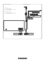
Montaggio cavo scaldante tubi allacciamento (Fig. 2)
Utilizzare il cavo scaldante (2) che fuoriesce dalla camera stagna per avvolgere
in direzione del muro il tubo riempimento impianto. Passare poi con il minor
tratto possibile ad avvolgere il tubo ritorno impianto in direzione opposta e il
tubo mandata impianto. Fissare il cavo scaldante ai tubi mediante 6 fascette (un
ssaggio ad ogni estremità del tubo).
Fissare il clicson (4) di controllo del cavo scaldante nella parte esterna della
caldaia, utilizzando le viti già presenti (5).
Montaggio cavo scaldante tubi allacciamento (incasso) (Fig. 4)
Utilizzare il cavo scaldante (2) che fuoriesce dalla camera stagna per avvolgere
verso il basso il tubo riempimento impianto. Passare poi con il minor tratto
possibile ad avvolgere il tubo ritorno impianto in direzione opposta e il tubo
mandata impianto. Fissare il cavo scaldante ai tubi mediante 6 fascette (un
ssaggio ad ogni estremità del tubo).
Fissare il clicson (4) di controllo del cavo scaldante nella parte esterna della
caldaia, utilizzando le viti già presenti (5).
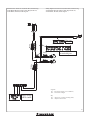
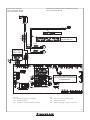
Collegamenti elettrici (Fig. 29)
Collegare quindi il kit antigelo come di seguito descritto. Cavo grigio cavo scal-
dante al cavo nero clicson. Cavo bianco cavo scaldante al cavo bianco aggiuntivo
presente nel kit. Cavo marrone clicson al morsetto A della morsettiera presente
nel vano allacciamento. Cavo bianco aggiuntivo presente nel kit al morsetto
B della morsettiera presente nel vano allacciamento. Sistemare i cavi di colle-
gamento nel vano allacciamento elettrico sotto al cavo di alimentazione della
caldaia già presente facendo attenzione che i due morsetti volanti rimangano
all'interno del vano allacciamento.
VICTRIX TERA PLUS VICTRIX HYBRID PLUS
MODELS
Assembling the heating cable inside the boiler (Fig. 1 - 3)
Invert the cable clamp (3) direction on the heating cable (2).
Remove the cap at the base of the sealed chamber and slide the heating cable (2)
into it. Slide the cable, keeping the terminals outside the boiler until the cable
clamp (3) pre-assembled on the heating cable (2) has been inserted in the hole.
Secure the cable clamp (3) to the metal-sheet plate using the ring nut in the kit.
Wrap the heating cable (2) around the lower part of the siphon (1) 1 time
(3 times for Victrix Tera Plus). en secure it with the zip ties in the kit (use 2
ties in series for each fastening point).
Assembling the connection pipe heating cable (Fig. 2)
Wrap the heating cable (2) emerging from the sealed chamber around the system
lling pipe winding it towards the wall. en, with the shortest length possible,
wrap it around the system return pipe, winding it in the opposite direction, and
around the system ow pipe. Secure the heating cable to the pipes using 6 zip
ties (fasten at each end of the pipe).
Secure the heating cable control Klixon thermostat (4) to the outer part of the
boiler using the screws (5) that are already there.
Assembling the connection pipe heating cable (container) (Fig. 4)
Wrap the heating cable (2) emerging from the sealed chamber around the sys-
tem lling pipe, winding it downwards. en, with the shortest length possible,
wrap it around the system return pipe, winding it in the opposite direction, and
around the system ow pipe. Secure the heating cable to the pipes using 6 zip
ties (fasten at each end of the pipe).
Secure the heating cable control Klixon thermostat (4) to the outer part of the
boiler using the screws (5) that are already there.
Electrical connections (Fig. 29)
en connect the antifreeze kit as described below. Grey cable heating cable to
the black Klixon thermostat cable. White cable heating cable to the additional
white cable in the kit. Klixon thermostat brown cable to terminal A of the ter-
minal board in the connection compartment. Additional white cable in the kit
to terminal B of the terminal board in the connection compartment. Arrange
the connection cables in the electrical connection compartment under the boiler
power cable that is already there, making sure that the two single-pole terminals
stay inside the connection compartment.

1
3
2
3
4
2
5
1
3
2
3
4
2
5
5
12
Victrix Serie TT Plus
Victrix Tera Plus - Victrix Hybrid Plus Victrix Serie TT Plus - Victrix Tera Plus - Victrix Hybrid Plus
4
Victrix Serie TT Plus (incasso / container)
Victrix Tera Plus (incasso / container)
Victrix Hybrid Plus (incasso / container)
3

6
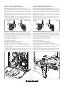
MODELLI VICTRIX SERIE TT VICTRIX TERA
VICTRIX TERA VIP VICTRIX HYBRID
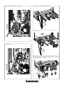
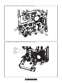
Montaggio cavo scaldante interno caldaia (Fig. 5 - 7)
Invertire l'orientamento del pressacavo (3) sul cavo scaldante (2).
Eliminare il tappo presente alla base della camera stagna e far scorrere al suo
interno il cavo scaldante (2), far scorrere il cavo tenendo i terminali all'esterno
della caldaia no ad inserire nel foro il pressacavo (3) preassemblato sul cavo
scaldante (2). Fissare il pressacavo (3) alla lamiera per mezzo della ghiera
presente nel kit.
Avvolgere il cavo scaldante (2) attorno alla parte inferiore del sifone (1) per 1
giro (3 giri per Victrix Tera), ssarlo quindi con le fascette presenti all'interno
del kit (usare 2 fascette in serie per ogni punto di ssaggio).
Montaggio cavo scaldante tubi allacciamento (Fig. 6)
Utilizzare il cavo scaldante (2) che fuoriesce dalla camera stagna per
avvolgere in direzione del muro il tubo uscita acqua calda sanitario. Passare
poi con il minor tratto possibile ad avvolgere il tubo entrata acqua sanitario
in direzione opposta. Passare poi con il minor tratto possibile ad avvolgere
il tubo ritorno impianto in direzione opposta e il tubo mandata impianto.
Fissare il cavo scaldante ai tubi mediante 4 fascette (un ssaggio ad ogni
estremità del tubo).
Fissare il clicson (4) di controllo del cavo scaldante nella parte esterna della
caldaia, utilizzando le viti già presenti (5).
Montaggio cavo scaldante tubi allacciamento (incasso) (Fig. 8)
Utilizzare il cavo scaldante (2) che fuoriesce dalla camera stagna per avvolgere
verso il basso il tubo uscita acqua calda sanitario (1). Passare poi con il minor
tratto possibile ad avvolgere il tubo entrata acqua sanitario in direzione opposta.
Passare poi con il minor tratto possibile ad avvolgere il tubo ritorno impianto in
direzione opposta e il tubo mandata impianto. Fissare il cavo scaldante ai tubi
mediante 4 fascette (un ssaggio ad ogni estremità del tubo).
Fissare il clicson (4) di controllo del cavo scaldante nella parte esterna della
caldaia, utilizzando le viti già presenti (5).
Collegamenti elettrici (Fig. 29)
Collegare quindi il kit antigelo come di seguito descritto.
Cavo grigio cavo scaldante al cavo nero clicson.
Cavo bianco cavo scaldante al cavo bianco aggiuntivo presente nel kit.
Cavo marrone clicson al morsetto A della morsettiera presente nel vano al-
lacciamento.
Cavo bianco aggiuntivo presente nel kit al morsetto B della morsettiera presente
nel vano allacciamento.
Sistemare i cavi di collegamento nel vano allacciamento elettrico sotto al cavo di
alimentazione della caldaia già presente facendo attenzione che i due morsetti
volanti rimangano all'interno del vano allacciamento.
VICTRIX TT SERIES VICTRIX TERA VICTRIX
TERA VIP VICTRIX HYBRID MODELS
Assembling the heating cable inside the boiler (Fig. 5 - 7)
Invert the cable clamp (3) direction on the heating cable (2).
Remove the cap at the base of the sealed chamber and slide the heating cable (2)
into it. Slide the cable, keeping the terminals outside the boiler until the cable
clamp (3) pre-assembled on the heating cable (2) has been inserted in the hole.
Secure the cable clamp (3) to the metal-sheet plate using the ring nut in the kit.
Wrap the heating cable (2) around the lower part of the siphon (1) 1 time
(3 times for Victrix Tera). en secure it with the zip ties in the kit (use 2 ties
in series for each fastening point).
Assembling the connection pipe heating cable (Fig. 6)
Wrap the heating cable (2) emerging from the sealed chamber around the
domestic hot water outlet pipe, winding it towards the wall. en, with the
shortest length possible, wrap it around the domestic hot water inlet pipe,
winding it in the opposite direction. en, with the shortest length possible,
wrap it around the system return pipe, winding it in the opposite direction,
and around the system ow pipe. Secure the heating cable to the pipes using 4
zip ties (fasten at each end of the pipe).
Secure the heating cable control Klixon thermostat (4) to the outer part of the
boiler using the screws (5) that are already there.
Assembling the connection pipe heating cable (container) (Fig. 8)
Wrap the heating cable (2) emerging from the sealed chamber around the do-
mestic hot water outlet pipe (1), winding it downwards. en, with the shortest
length possible, wrap it around the domestic hot water inlet pipe, winding it in
the opposite direction. en, with the shortest length possible, wrap it around
the system return pipe, winding it in the opposite direction, and around the
system ow pipe. Secure the heating cable to the pipes using 4 zip ties (fasten
at each end of the pipe).
Secure the heating cable control Klixon thermostat (4) to the outer part of the
boiler using the screws (5) that are already there.
Electrical connections (Fig. 29)
en connect the antifreeze kit as described below.
Grey cable heating cable to the black Klixon thermostat cable.
White cable heating cable to the additional white cable in the kit.
Klixon thermostat brown cable to terminal A of the terminal board in the
connection compartment.
Additional white cable in the kit to terminal B of the terminal board in the
connection compartment.
Arrange the connection cables in the electrical connection compartment under
the boiler power cable that is already there, making sure that the two single-pole
terminals stay inside the connection compartment.

1
3
2
3
4
2
5
1
3
2
3
4
2
5
3
4
2
5
7
5
6
Victrix Serie TT
Victrix Tera - Victrix Tera Vip - Victrix Hybrid Victrix Serie TT - Victrix Tera - Victrix Hybrid
8
Victrix Serie TT (incasso / container) - Victrix Tera (incasso / container)
- Victrix Hybrid (incasso / container)
7
Victrix Tera Vip

8
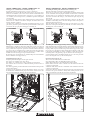
VICTRIX OMNIA ATTACCO DIN
Montaggio cavo scaldante tubi allacciamento (Fig. 9)
Fissare il clicson (4) di controllo del cavo scaldante nella parte esterna della
caldaia, utilizzando le viti già presenti.
Utilizzare il cavo scaldante (2) già ssato e disponibile sotto alla caldaia per
avvolgere di 4 spire verso il basso il tubo uscita acqua calda sanitario.
Passare poi con il minor tratto possibile ad avvolgere di 4 spire il tubo entrata
acqua fredda sanitario in direzione opposta.
Fissare il cavo scaldante ai tubi mediante 4 fascette (un ssaggio ad ogni
estremità del tubo).
Montaggio cavo scaldante interno caldaia (Fig. 10)
Eliminare il passacavo.
Il cavo scaldante deve essere fatto passare a lato del cruscotto dopo aver ssato
lo stesso agli allacciamenti idraulici (ingresso e uscita sanitario).
Avvolgere il cavo scaldante (2) attorno alla parte inferiore del sifone (1) per
3 giri, ssarlo quindi in 2 punti con le fascette presenti all'interno del kit
(usare 2 fascette in serie per ogni punto di ssaggio).
Collegamenti elettrici (Fig. 29)
Collegare quindi il kit antigelo come di seguito descritto.
Cavo grigio cavo scaldante al cavo nero clicson.
Cavo bianco cavo scaldante al cavo bianco aggiuntivo presente nel kit.
Cavo marrone clicson al morsetto A della morsettiera presente nel cruscotto.
Cavo bianco aggiuntivo presente nel kit al morsetto B della morsettiera presente
nel cruscotto.
VICTRIX OMNIA DIN COUPLING
Assembling the connection pipe heating cable (Fig. 9)
Secure the heating cable control Klixon thermostat (4) to the outer part of the
boiler using the screws that are already there.
Use the heating cable (2) already xed and available under the boiler to wind
the domestic hot water outlet pipe 4 times downwards.
en, with the shortest length possible, wrap it around the domestic cold water
inlet pipe 4 times, winding it in the opposite direction.
Secure the heating cable to the pipes using 4 zip ties (fasten at each end of the
pipe).
Assembling the heating cable inside the boiler (Fig. 10)
Eliminate the fairlead.
Feed the heating cable to the side of the control panel aer xing it to the hy-
draulic connections (DHW inlet and outlet).
Wrap the heating cable (2) around the lower part of the siphon (1) 3 times.
en secure it in 2 points with the zip ties in the kit (use 2 ties in series for each
fastening point).
Electrical connections (Fig. 29)
en connect the antifreeze kit as described below.
Grey cable heating cable to the black Klixon thermostat cable.
White cable heating cable to the additional white cable in the kit.
Klixon thermostat brown cable to terminal A of the terminal board in the
control panel.
Additional white cable in the kit to terminal B of the terminal board in the
control panel.

3
4
2
1
2
9
Victrix Omnia attacco DIN / Victrix Omnia DIN coupling
Victrix Omnia attacco DIN / Victrix Omnia DIN coupling
9
10

10
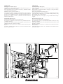
VICTRIX OMNIA ATTACCO DIMA IMMERGAS
Montaggio cavo scaldante tubi allacciamento (Fig. 11)
Fissare il clicson (4) di controllo del cavo scaldante nella parte esterna della
caldaia, utilizzando le viti già presenti.
Utilizzare il cavo scaldante (2) già ssato e disponibile sotto alla caldaia per
avvolgere di 4 spire verso il basso il tubo uscita acqua calda sanitario.
Passare poi con il minor tratto possibile ad avvolgere di 4 spire il tubo entrata
acqua fredda sanitario in direzione opposta.
Fissare il cavo scaldante ai tubi mediante 4 fascette (un ssaggio ad ogni
estremità del tubo).
Montaggio cavo scaldante interno caldaia (Fig. 12)
Eliminare il passacavo.
Il cavo scaldante deve essere fatto passare a lato del cruscotto dopo aver ssato
lo stesso agli allacciamenti idraulici (ingresso e uscita sanitario).
Avvolgere il cavo scaldante (2) attorno alla parte inferiore del sifone (1) per
3 giri, ssarlo quindi in 2 punti con le fascette presenti all'interno del kit
(usare 2 fascette in serie per ogni punto di ssaggio).
Collegamenti elettrici (Fig. 29)
Collegare quindi il kit antigelo come di seguito descritto.
Cavo grigio cavo scaldante al cavo nero clicson.
Cavo bianco cavo scaldante al cavo bianco aggiuntivo presente nel kit.
Cavo marrone clicson al morsetto A della morsettiera presente nel cruscotto.
Cavo bianco aggiuntivo presente nel kit al morsetto B della morsettiera presente
nel cruscotto.
VICTRIX OMNIA IMMERGAS TEMPLATE COUPLING
Assembling the connection pipe heating cable (Fig. 11)
Secure the heating cable control Klixon thermostat (4) to the outer part of the
boiler using the screws that are already there.
Use the heating cable (2) already xed and available under the boiler to wind
the domestic hot water outlet pipe 4 times downwards.
en, with the shortest length possible, wrap it around the domestic cold water
inlet pipe 4 times, winding it in the opposite direction.
Secure the heating cable to the pipes using 4 zip ties (fasten at each end of the
pipe).
Assembling the heating cable inside the boiler (Fig. 12)
Eliminate the fairlead.
Feed the heating cable to the side of the control panel aer xing it to the hy-
draulic connections (DHW inlet and outlet).
Wrap the heating cable (2) around the lower part of the siphon (1) 3 times.
en secure it in 2 points with the zip ties in the kit (use 2 ties in series for each
fastening point).
Electrical connections (Fig. 29)
en connect the antifreeze kit as described below.
Grey cable heating cable to the black Klixon thermostat cable.
White cable heating cable to the additional white cable in the kit.
Klixon thermostat brown cable to terminal A of the terminal board in the
control panel.
Additional white cable in the kit to terminal B of the terminal board in the
control panel.

3
4
2
1
2
11
Victrix Omnia attacco Dima Immergas / Victrix Omnia Immergas template coupling
Victrix Omnia attacco Dima Immergas / Victrix Omnia Immergas template coupling
11
12

3
4
2
12
VICTRIX OMNIA INCASSO
Montaggio cavo scaldante tubi allacciamento (incasso) (Fig. 13)
Fissare il clicson (4) di controllo del cavo scaldante nella parte esterna della
caldaia, utilizzando le viti già presenti.
Utilizzare il cavo scaldante (2) già ssato e disponibile sotto alla caldaia per
avvolgere di 4 spire verso il basso il tubo uscita acqua calda sanitario.
Passare poi con il minor tratto possibile ad avvolgere di 4 spire il tubo entrata
acqua fredda sanitario in direzione opposta.
Fissare il cavo scaldante ai tubi mediante 4 fascette (un ssaggio ad ogni
estremità del tubo).
Montaggio cavo scaldante interno caldaia (Fig. 9 - 11)
Eliminare il passacavo.
Il cavo scaldante deve essere fatto passare a lato del cruscotto dopo aver ssato
lo stesso agli allacciamenti idraulici (ingresso e uscita sanitario).
Avvolgere il cavo scaldante (2) attorno alla parte inferiore del sifone (1) per
3 giri, ssarlo quindi in 2 punti con le fascette presenti all'interno del kit
(usare 2 fascette in serie per ogni punto di ssaggio).
Collegamenti elettrici (Fig. 29)
Collegare quindi il kit antigelo come di seguito descritto.
Cavo grigio cavo scaldante al cavo nero clicson.
Cavo bianco cavo scaldante al cavo bianco aggiuntivo presente nel kit.
Cavo marrone clicson al morsetto A della morsettiera presente nel cruscotto.
Cavo bianco aggiuntivo presente nel kit al morsetto B della morsettiera presente
nel cruscotto.
VICTRIX OMNIA CONTAINER
Assembling the connection pipe heating cable (container) (Fig. 13)
Secure the heating cable control Klixon thermostat (4) to the outer part of the
boiler using the screws that are already there.
Use the heating cable (2) already xed and available under the boiler to wind
the domestic hot water outlet pipe 4 times downwards.
en, with the shortest length possible, wrap it around the domestic cold water
inlet pipe 4 times, winding it in the opposite direction.
Secure the heating cable to the pipes using 4 zip ties (fasten at each end of the
pipe).
Assembling the heating cable inside the boiler (Fig. 9 - 11)
Eliminate the fairlead.
Feed the heating cable to the side of the control panel aer xing it to the hy-
draulic connections (DHW inlet and outlet).
Wrap the heating cable (2) around the lower part of the siphon (1) 3 times.
en secure it in 2 points with the zip ties in the kit (use 2 ties in series for each
fastening point).
Electrical connections (Fig. 29)
en connect the antifreeze kit as described below.
Grey cable heating cable to the black Klixon thermostat cable.
White cable heating cable to the additional white cable in the kit.
Klixon thermostat brown cable to terminal A of the terminal board in the
control panel.
Additional white cable in the kit to terminal B of the terminal board in the
control panel.
Victrix Omnia (incasso) / Victrix Omnia (container)
13

2
1
33
4
13
MAGIS PRO MAGIS PRO V2
Montaggio kit (Fig. 14)
Eliminare il connettore presente sul cavo del clicson (2) tagliandolo in prossi-
mità del connettore.
Fissare il clicson (2) nella parte inferiore del generatore utilizzando le viti fornite
nel kit (3) oppure quelle presenti sulla lamiera stessa.
Slare il passacavo presente sul cavo scaldante (1), avvolgere quindi il cavo ai
tubi sanitari utilizzando tutto il cavo disponibile. Fissare il cavo scaldante ai tubi
mediante le fascette fornite nel kit (ssare il cavo ad ogni estremità del tubo).
Collegamenti elettrici Magis Pro (Fig. 30)
Collegare un cavo del clicson al morsetto A.
Collegare un cavo del cavo scaldante al morsetto B.
Unire il cavo del clicson con il cavo del cavo scaldante mediante il mammut
(4) presente kit.
Sistemare i cavi di collegamento nel vano allacciamento elettrico facendo at-
tenzione che i morsetti volanti rimangano all'interno del vano allacciamento.
Collegamenti elettrici Magis Pro V2 (Fig. 30)
Rispettare la polarità L - N, collegando il cavo del clicson alla fase (L) ed il cavo
della resistenza scaldante al neutro (N).
Unire il cavo del clicson con il cavo del cavo scaldante mediante il morsetto
(4) presente nel kit.
Sistemare i cavi di collegamento nel vano allacciamento elettrico facendo at-
tenzione che i morsetti volanti rimangano all'interno del vano allacciamento.
Collegare i cavi alla rete di alimentazione a 230 V ± 10% / 50 Hz.
14
MAGIS PRO MAGIS PRO V2
Kit assembly (Fig. 14)
Remove the connector on the Klixon thermostat cable (2) by cutting it near
the connector.
Secure the Klixon thermostat (2) to the lower part of the generator, using the
screws provided in the kit (3) or those on the metal-sheet plate.
Remove the fairlead on the heating cable (1), then wrap the cable around the
domestic hot water pipes, using all the cable available. Secure the heating cable
to the pipes using the zip ties provided in the kit (fasten the cable at the end
of each pipe).
Magis Pro electrical connections (Fig. 30)
Connect a Klixon thermostat cable to terminal A.
Connect a cable from the heating cable to terminal B.
Join the Klixon thermostat cable with the heating cable using the strip connector
(4) in the kit.
Arrange the connection cables in the electrical connection compartment,
making sure the single-pole terminals stay inside the connection compartment.
Magis Pro V2 electrical connections (Fig. 30)
Respect the L - N polarity, connecting the Klixon cable to phase (L) and the
heating element cable to neutral (N).
Join the Klixon thermostat cable with the heating cable using the terminal (4)
present in the kit.
Arrange the connection cables in the electrical connection compartment,
making sure the single-pole terminals stay inside the connection compartment.
Connect the cables to the 230 V ± 10% / 50 Hz power supply.

1
2
3
1
2
4
3
5
14
MODELLI VICTRIX EXA, INTEC COMBI INTERNAL /
EXTERNAL, INTEC SYSTEM INTERNAL / EXTERNAL
Montaggio cavo scaldante interno caldaia (Fig. 15)
Slare il cavo scaldante dal pressacavo e inserirlo al contrario.
Eliminare il tappo presente alla base della camera stagna e far scorrere al suo
interno il cavo scaldante (2), tenendo i terminali all'esterno della caldaia no ad
avere la lunghezza di cavo necessaria per avvolgere il sifone. Fissare il pressacavo
(5) alla lamiera per mezzo della ghiera presente nel kit.
Avvolgere il cavo scaldante (2) attorno alla parte inferiore del sifone (1) per 3
giri, ssarlo quindi in 2 punti con le fascette presenti all'interno del kit (usare 2
fascette in serie per ogni punto di ssaggio).
Fissare il clicson (4) di controllo del cavo scaldante nella parte esterna della
caldaia, nei pressi della valvola del gas utilizzando le viti già presenti (3).
Montaggio cavo scaldante tubi allacciamento (Fig. 16)
Utilizzare il cavo scaldante (3) che fuoriesce dalla camera stagna per avvolgere
di 4 spire in direzione del muro il tubo entrata acqua sanitario (1). Passare poi
con il minor tratto possibile ad avvolgere di 4 spire il tubo uscita acqua calda
sanitario (2) in direzione opposta. Fissare il cavo scaldante ai tubi mediante 4
fascette (un ssaggio ad ogni estremità del tubo).
Attenzione (modelli Intec): avvolgere il cavo scaldante ai tubi allacciamento
sanitario secondo le proprie esigenze impiantistiche.
Collegamenti elettrici (Fig. 31)
Collegare quindi il kit antigelo come di seguito descritto e rappresentato nello
schema elettrico.
Cavo grigio cavo scaldante al cavo nero clicson.
Cavo bianco cavo scaldante al cavo bianco aggiuntivo presente nel kit.
Cavo marrone clicson al morsetto L di alimentazione caldaia.
Cavo bianco aggiuntivo presente nel kit al morsetto N di alimentazione caldaia.
Sistemare i cavi di collegamento alla scheda di caldaia sotto al cavo di alimen-
tazione della caldaia già presente.
16
15
VICTRIX EXA, INTEC COMBI INTERNAL /
EXTERNAL, INTEC SYSTEM INTERNAL / EXTERNAL
MODELS
Assembling the heating cable inside the boiler (Fig. 15)
Slide the heating cable out of the cable clamp and insert it backwards.
Remove the cap at the base of the sealed chamber and slide the heating cable
(2) into it, keeping the terminals outside of the boiler until you have the length
of cable necessary to wrap around the siphon. Secure the cable clamp (5) to the
metal-sheet plate using the ring nut in the kit.
Wrap the heating cable (2) around the lower part of the siphon (1) 3 times.
en secure it in 2 points with the zip ties in the kit (use 2 ties in series for each
fastening point).
Secure the heating cable control Klixon thermostat (4) to the outer part of the
boiler near the gas valve, using the screws that are already there (3).
Assembling the connection pipe heating cable (Fig. 16)
Wrap the heating cable (3) emerging from the sealed chamber around the do-
mestic hot water inlet pipe (1) 4 times, winding it towards the wall. en, with
the shortest length possible, wrap it around the domestic hot water outlet pipe
(2) 4 times, winding it in the opposite direction. Secure the heating cable to the
pipes using 4 zip ties (fasten at each end of the pipe).
Attention (Intec models): wind the heating cable around the D..H.W. connec-
tion according to your installation requirements.
Electrical connections (Fig. 31)
en connect the antifreeze kit as described and illustrated below in the wiring
diagram.
Grey cable heating cable to the black Klixon thermostat cable.
White cable heating cable to the additional white cable in the kit.
Brown Klixon thermostat cable to boiler supply voltage terminal L.
Additional white cable in the kit to boiler supply voltage terminal N.
Arrange the boiler board connection cables under the boiler power cable that
is already there.

1
2
1
2
1
2
1
2
1
3
2
3
4
2
5
15
19 20
MAGIS COMBO MAGIS COMBO V2
Montaggio cavo scaldante interno unità interna (Fig. 17)
Invertire l'orientamento del pressacavo (3) sul cavo scaldante (2).
Eliminare il tappo presente alla base della camera stagna e far scorrere al suo
interno il cavo scaldante (2), far scorrere il cavo tenendo i terminali all'esterno
dell'unità interna no ad inserire nel foro il pressacavo (3) preassemblato sul
cavo scaldante (2). Fissare il pressacavo (3) alla lamiera per mezzo della ghiera
presente nel kit.
La posizione del sifone montato dentro l'unità interna non permette l'instal-
lazione del cavo scaldante come indicato in gura. Smontare il sifone come
indicato sul libretto istruzioni.
Avvolgere il cavo scaldante (2) attorno alla parte inferiore del sifone (1) per 2
giri, ssarlo quindi in 2 punti con le fascette presenti all'interno del kit (usare 2
fascette in serie per ogni punto di ssaggio) come da Fig. 17.
17 18
ANTERIORE FRONTPOSTERIORE REAR
MAGIS COMBO MAGIS COMBO V2
Assembling the heating cable inside the indoor unit (Fig. 18)
Invert the cable clamp (3) direction on the heating cable (2).
Remove the cap at the base of the sealed chamber and slide the heating cable
(2) into it. Slide the cable, keeping the terminals outside the indoor unit until
the cable clamp (3) pre-assembled on the heating cable (2) has been inserted
in the hole. Secure the cable clamp (3) to the metal-sheet plate using the ring
nut in the kit.
e position of the siphon assembled in the indoor unit does not allow the
installation of the heating cable as shown in the gure. Remove the siphon as
indicated in the instruction sheet.
Wrap the heating cable (2) around the lower part of the siphon (1) 2 times.
en secure it in 2 points with the zip ties in the kit (use 2 ties in series for each
fastening point) as shown in Fig. 18.
Assembling the connection pipe heating cable (Fig. 19 - 20)
Wrap the heating cable (2) emerging from the sealed chamber around the
domestic hot water inlet pipe 4 times, winding it towards the wall. en, with
the shortest length possible, wrap it around the domestic hot water outlet pipe
4 times, winding it in the opposite direction. Secure the heating cable to the
pipes using 4 zip ties (fasten at each end of the pipe).
Secure the heating cable control Klixon thermostat (4) to the outer part of the
indoor unit using the screws (5) that are already there.
Electrical connections (Fig. 29)
en connect the antifreeze kit as described below.
Grey cable heating cable to the black Klixon thermostat cable.
White cable heating cable to the additional white cable in the kit.
Klixon thermostat brown cable to terminal A of the terminal board in the
connection compartment.
Additional white cable in the kit to terminal B of the terminal board in the
connection compartment.
Arrange the connection cables in the electrical connection compartment under
the indoor unit power cable that is already there, making sure that the two
single-pole terminals stay inside the connection compartment.
Montaggio cavo scaldante tubi allacciamento (Fig. 19 - 20)
Utilizzare il cavo scaldante (2) che fuoriesce dalla camera stagna per avvolgere
di 4 spire in direzione del muro il tubo entrata acqua sanitario. Passare poi con il
minor tratto possibile ad avvolgere di 4 spire il tubo uscita acqua calda sanitario
in direzione opposta. Fissare il cavo scaldante ai tubi mediante 4 fascette (un
ssaggio ad ogni estremità del tubo).
Fissare il clicson (4) di controllo del cavo scaldante nella parte esterna dell'unità
interna, utilizzando le viti già presenti (5).
Collegamenti elettrici (Fig. 29)
Collegare quindi il kit antigelo come di seguito descritto.
Cavo grigio cavo scaldante al cavo nero clicson.
Cavo bianco cavo scaldante al cavo bianco aggiuntivo presente nel kit.
Cavo marrone clicson al morsetto A della morsettiera presente nel vano al-
lacciamento.
Cavo bianco aggiuntivo presente nel kit al morsetto B della morsettiera presente
nel vano allacciamento.
Sistemare i cavi di collegamento nel vano allacciamento elettrico sotto al cavo
di alimentazione dell'unità interna già presente facendo attenzione che i due
morsetti volanti rimangano all'interno del vano allacciamento.

1
2
1
2
1
2
1
2
1
3
2
3
4
2
5
16
23 24
MAGIS COMBO PLUS MAGIS COMBO PLUS V2
Montaggio cavo scaldante interno unità interna (Fig. 21)
Invertire l'orientamento del pressacavo (3) sul cavo scaldante (2).
Eliminare il tappo presente alla base della camera stagna e far scorrere al suo
interno il cavo scaldante (2), far scorrere il cavo tenendo i terminali all'esterno
dell'unità interna no ad inserire nel foro il pressacavo (3) preassemblato sul
cavo scaldante (2). Fissare il pressacavo (3) alla lamiera per mezzo della ghiera
presente nel kit.
La posizione del sifone montato dentro l'unità interna non permette l'instal-
lazione del cavo scaldante come indicato in gura. Smontare il sifone come
indicato sul libretto istruzioni.
Avvolgere il cavo scaldante (2) attorno alla parte inferiore del sifone (1) per 2
giri, ssarlo quindi in 2 punti con le fascette presenti all'interno del kit (usare
2 fascette in serie per ogni punto di ssaggio) come da Fig. 21.
21 22
ANTERIORE FRONTPOSTERIORE REAR
MAGIS COMBO PLUS MAGIS COMBO PLUS V2
Assembling the heating cable inside the indoor unit (Fig. 22)
Invert the cable clamp (3) direction on the heating cable (2).
Remove the cap at the base of the sealed chamber and slide the heating cable
(2) into it. Slide the cable, keeping the terminals outside the indoor unit until
the cable clamp (3) pre-assembled on the heating cable (2) has been inserted
in the hole. Secure the cable clamp (3) to the metal-sheet plate using the ring
nut in the kit.
e position of the siphon assembled in the indoor unit does not allow the
installation of the heating cable as shown in the gure. Remove the siphon as
indicated in the instruction sheet.
Wrap the heating cable (2) around the lower part of the siphon (1) 2 times.
en secure it in 2 points with the zip ties in the kit (use 2 ties in series for each
fastening point) as shown in Fig. 22.
Assembling the connection pipe heating cable (Fig. 23 - 24)
Wrap the heating cable (2) emerging from the sealed chamber around the storage
tank return pipe 2 times, winding it towards the wall. en, with the shortest
length possible, wrap it around the storage tank outlet ow pipe 2 times, wind-
ing it in the opposite direction. en, with the shortest length possible, wrap
it around the system lling pipe 4 times, winding it towards the wall. Secure
the heating cable to the pipes using 6 zip ties (fasten at each end of the pipe).
Secure the heating cable control Klixon thermostat (4) to the outer part of the
indoor unit using the screws (5) that are already there.
Electrical connections (Fig. 29)
en connect the antifreeze kit as described below.
Grey cable heating cable to the black Klixon thermostat cable.
White cable heating cable to the additional white cable in the kit.
Klixon thermostat brown cable to terminal A of the terminal board in the
connection compartment.
Additional white cable in the kit to terminal B of the terminal board in the
connection compartment.
Arrange the connection cables in the electrical connection compartment under
the indoor unit power cable that is already there, making sure that the two
single-pole terminals stay inside the connection compartment.
Montaggio cavo scaldante tubi allacciamento (Fig. 23 - 24)
Utilizzare il cavo scaldante (2) che fuoriesce dalla camera stagna per avvolgere di
2 spire in direzione del muro il tubo ritorno bollitore. Passare poi con il minor
tratto possibile ad avvolgere di 2 spire il tubo mandata bollitore in direzione
opposta. Passare poi con il minor tratto possibile ad avvolgere di 4 spire il tubo
riempimento impianto in direzione del muro. Fissare il cavo scaldante ai tubi
mediante 6 fascette (un ssaggio ad ogni estremità del tubo).
Fissare il clicson (4) di controllo del cavo scaldante nella parte esterna dell'unità
interna, utilizzando le viti già presenti (5).
Collegamenti elettrici (Fig. 29)
Collegare quindi il kit antigelo come di seguito descritto.
Cavo grigio cavo scaldante al cavo nero clicson.
Cavo bianco cavo scaldante al cavo bianco aggiuntivo presente nel kit.
Cavo marrone clicson al morsetto A della morsettiera presente nel vano al-
lacciamento.
Cavo bianco aggiuntivo presente nel kit al morsetto B della morsettiera presente
nel vano allacciamento.
Sistemare i cavi di collegamento nel vano allacciamento elettrico sotto al cavo
di alimentazione dell'unità interna già presente facendo attenzione che i due
morsetti volanti rimangano all'interno del vano allacciamento.

1
2
3
4
4
5
6
7
5
8
9
13
14
7
12
11 10
3
17
25
TRIO PACK
Montaggio cavo scaldante (Fig. 25)
Fissare il clicson (2) di controllo cavo scaldante sulla squadretta di supporto (5)
utilizzando le viti (3) fornite in dotazione.
Fissare la squadretta (5) provvista di clicson sul tubo (7) utilizzando il collare
(8) e la vite (9) fornite in dotazione.
Eliminare il passacavo dal tubo scaldante (1).
Avvolgere il cavo scaldante (1) sul tubo (7) di collegamento con il vaso di espan-
sione iniziando dal gruppo di riempimento in ottone (6) no alla squadretta di
ssaggio clicson (5) utilizzando tutto il cavo disponibile come indicato in Fig. 25.
Bloccare il cavo scaldante (1) sul tubo (7) utilizzando un numero di fascette
fornite in dotazione idoneo.
Collegamenti elettrici (Fig. 29)
Collegare quindi il kit antigelo come di seguito descritto.
Cavo grigio cavo scaldante (10) al cavo nero clicson (11) utilizzando il morsetto
(4) fornito in dotazione.
Cavo bianco cavo scaldante (12) al cavo bianco aggiuntivo presente nel kit (13)
utilizzando il morsetto (4) fornito in dotazione.
Cavo marrone clicson (14) al morsetto A della morsettiera presente nel quadro
elettrico.
Cavo bianco aggiuntivo presente nel kit (13) al morsetto B della morsettiera
presente nel quadro elettrico.
TRIO PACK
Assembly of heating cable (Fig. 25)
Fix the heating cable control clicson (2) on the support bracket (5) using the
screws (3) supplied.
Fix the bracket (5) provided with clicson on the pipe (7) using the collar (8)
and the screw (9) supplied.
Remove the grommet from the heating pipe (1).
Wind the heating cable (1) on the connection pipe (7) with the expansion tank
starting from the brass lling unit (6) up to the clicson xing bracket (5) using
all the available cable as shown in Fig. 25.
Block the heating cable (1) on the pipe (7) using a suitable number of clamps
supplied.
Electrical connections (Fig. 29)
en connect the antifreeze kit as described below.
Grey cable heating cable (10) to the black Klixon thermostat cable (11) using
the clamp (4) supplied.
White cable heating cable (12) to the additional white cable in the kit (13) using
the clamp (4) supplied.
Klixon thermostat brown cable (14) to terminal A of the terminal board in the
electrical cabinet.
Additional white cable in the kit (13) to terminal B of the terminal board in
the electrical cabinet.

18
VICTRIX SUPERIOR VICTRIX SUPERIOR PLUS
Montaggio cavo scaldante interno caldaia (Fig. 26)
Invertire l'orientamento del pressacavo (3) sul cavo scaldante (2).
Eliminare il tappo presente alla base della camera stagna e far scorrere al suo
interno il cavo scaldante (2), far scorrere il cavo tenendo i terminali all'esterno
della caldaia no ad inserire nel foro il pressacavo (3) preassemblato sul cavo
scaldante (2). Fissare il pressacavo (3) alla lamiera per mezzo della ghiera
presente nel kit.
Avvolgere il cavo scaldante (2) attorno alla parte inferiore del sifone (1) per 3
giri, ssarlo quindi con le fascette presenti all'interno del kit (usare 2 fascette in
serie per ogni punto di ssaggio).
Montaggio cavo scaldante tubi allacciamento Victrix Superior (Fig. 27)
Utilizzare il cavo scaldante (2) che fuoriesce dalla camera stagna per
avvolgere in direzione del muro il tubo uscita acqua calda sanitario. Passare
poi con il minor tratto possibile ad avvolgere il tubo entrata acqua sanitario
in direzione opposta. Passare poi con il minor tratto possibile ad avvolgere
il tubo ritorno impianto in direzione opposta e il tubo mandata impianto.
Fissare il cavo scaldante ai tubi mediante 4 fascette (un ssaggio ad ogni
estremità del tubo).
Fissare il clicson (4) di controllo del cavo scaldante nella parte esterna della
caldaia, utilizzando le viti già presenti (5).
Montaggio cavo scaldante tubi allacciamento Victrix Superior Plus (Fig.
28)
Utilizzare il cavo scaldante (2) che fuoriesce dalla camera stagna per
avvolgere in direzione del muro il tubo entrata acqua sanitario. Passare
poi con il minor tratto possibile ad avvolgere il tubo ritorno impianto in
direzione opposta e il tubo mandata impianto. Fissare il cavo scaldante ai tubi
mediante 4 fascette (un ssaggio ad ogni estremità del tubo).
Fissare il clicson (4) di controllo del cavo scaldante nella parte esterna della
caldaia, utilizzando le viti già presenti (5).
Collegamenti elettrici (Fig. 29)
Collegare quindi il kit antigelo come di seguito descritto.
Cavo grigio cavo scaldante al cavo nero clicson.
Cavo bianco cavo scaldante al cavo bianco aggiuntivo presente nel kit.
Cavo marrone clicson al morsetto A della morsettiera presente nel vano al-
lacciamento.
Cavo bianco aggiuntivo presente nel kit al morsetto B della morsettiera presente
nel vano allacciamento.
Sistemare i cavi di collegamento nel vano allacciamento elettrico sotto al cavo di
alimentazione della caldaia già presente facendo attenzione che i due morsetti
volanti rimangano all'interno del vano allacciamento.
VICTRIX SUPERIOR VICTRIX SUPERIOR PLUS
Assembling the heating cable inside the boiler (Fig. 26)
Invert the cable clamp (3) direction on the heating cable (2).
Remove the cap at the base of the sealed chamber and slide the heating cable (2)
into it. Slide the cable, keeping the terminals outside the boiler until the cable
clamp (3) pre-assembled on the heating cable (2) has been inserted in the hole.
Secure the cable clamp (3) to the metal-sheet plate using the ring nut in the kit.
Wrap the heating cable (2) around the lower part of the siphon (1) 3 times . en
secure it with the zip ties in the kit (use 2 ties in series for each fastening point).
Assembling the connection pipe heating cable Victrix Superior (Fig. 27)
Wrap the heating cable (2) emerging from the sealed chamber around the
domestic hot water outlet pipe, winding it towards the wall. en, with the
shortest length possible, wrap it around the domestic hot water inlet pipe,
winding it in the opposite direction. en, with the shortest length possible,
wrap it around the system return pipe, winding it in the opposite direction,
and around the system ow pipe. Secure the heating cable to the pipes using 4
zip ties (fasten at each end of the pipe).
Secure the heating cable control Klixon thermostat (4) to the outer part of the
boiler using the screws (5) that are already there.
Assembling the connection pipe heating cable Victrix Superior Plus (Fig.
28)
Wrap the heating cable (2) emerging from the sealed chamber around the
domestic hot water inlet pipe. en, with the shortest length possible, wrap it
around the system return pipe, winding it in the opposite direction, and around
the system ow pipe. Secure the heating cable to the pipes using 4 zip ties (fasten
at each end of the pipe).
Secure the heating cable control Klixon thermostat (4) to the outer part of the
boiler using the screws (5) that are already there.
Electrical connections (Fig. 29)
en connect the antifreeze kit as described below.
Grey cable heating cable to the black Klixon thermostat cable.
White cable heating cable to the additional white cable in the kit.
Klixon thermostat brown cable to terminal A of the terminal board in the
connection compartment.
Additional white cable in the kit to terminal B of the terminal board in the
connection compartment.
Arrange the connection cables in the electrical connection compartment under
the boiler power cable that is already there, making sure that the two single-pole
terminals stay inside the connection compartment.

3
1
2
3
6
4
5
4
4
5
3
6
2
19
26
Victrix Superior
Victrix Superior - Victrix Superior Plus
28
27
Victrix Superior Plus

20
OPERAZIONI FINALI
Una volta eettuato l'assemblaggio del kit antigelo chiudere il cruscotto/quadro
elettrico del generatore, rimontare la mantellatura (chiudere il contenitore, solo
per Trio Pack).
- Ridare tensione al generatore per portarlo alle normali condizioni di funzio-
namento.
Avvertenze per il tecnico
Il kit antigelo è stato collaudato e testato in fabbrica, non occorre quindi testarlo
o collaudarlo al momento dell’installazione.
E’ però molto importante accertarsi di avere eettuato il corretto allacciamento
elettrico del kit, seguendo lo schema elettrico riportato nelle gure 29, 30 e 31
a seconda del modello.
Nelle gure 29, 30 e 31 a seconda del modello, è rappresentata la morsettiera che
è situata nel vano allacciamento elettrico posto nel cruscotto/quadro elettrico.
Il kit antigelo una volta installato è sempre collegato e funzionante.
La funzione antigelo sul circuito sanitario è però assicurata soltanto se:
- la caldaia/il generatore è correttamente allacciata/o al circuito di alimen-
tazione elettrica;
- l’interruttore generale è inserito;
- il fusibile della caldaia/del generatore è integro;
- i componenti del kit antigelo non sono in avaria.
In queste condizioni il circuito sanitario della caldaia/del generatore è pro-
tetto contro il gelo no ad una temperatura ambiente di -15°C.
FINAL OPERATIONS
Once the antifreeze kit has been assembled, close the generator control panel/
electrical cabinet and reassemble the casing (close the container, only for Trio
Pack).
- Restore power to the generator to bring it to normal operating conditions.
Recommendations for the technician
e antifreeze kit was inspected and tested in the factory; therefore, it does not
require testing or inspection upon installation.
However, it is very important to be sure to have made the kit electrical con-
nections properly, following the wiring diagram shown in gures 29, 30 or 31,
depending on the model.
Figures 29, 30 or 31, depending on the model, illustrates a terminal board
positioned in the electrical connection compartment located inside the control
board/electrical cabinet.
Once the antifreeze kit has been installed, it is always connected and operational.
e antifreeze function on the domestic hot water circuit is only guaranteed if:
- the boiler / generator is correctly connected to the electrical power supply
circuit;
- the main switch is engaged;
- the boiler/generator fuse is intact;
- the anti-freezing kit components are ecient.
Under these conditions, the boiler/generator domestic hot water circuit is
protected from freezing up to an ambient temperature of -15°C.
La pagina si sta caricando...
La pagina si sta caricando...
La pagina si sta caricando...
La pagina si sta caricando...
-
 1
1
-
 2
2
-
 3
3
-
 4
4
-
 5
5
-
 6
6
-
 7
7
-
 8
8
-
 9
9
-
 10
10
-
 11
11
-
 12
12
-
 13
13
-
 14
14
-
 15
15
-
 16
16
-
 17
17
-
 18
18
-
 19
19
-
 20
20
-
 21
21
-
 22
22
-
 23
23
-
 24
24


Immergas Victrix TT Series Manuale utente
- Tipo
- Manuale utente
in altre lingue
Documenti correlati
-
Immergas 3.024176 Manuale utente
-
-
Immergas COD.3.023950 Istruzioni per l'uso
-
-
-
-
-
-
Immergas CODE 3.032258 Istruzioni per l'uso
-