
IT IE
1
1
2
3
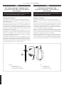
KIT SONDA MANDATA IMPIANTO PER
CALDAIA VICTRIX PRO - VICTRIX PRO V2
Cod. 3.024245
AVVERTENZE GENERALI.
Tutti i prodotti sono protetti con idoneo imballaggio da trasporto.
Il materiale deve essere immagazzinato in ambienti asciutti ed al
riparo dalle intemperie.
Il presente foglio istruzioni contiene informazioni tecniche relative
all’installazione del kit. Per quanto concerne le altre tematiche corre-
late all’installazione del kit stesso (a titolo esemplicativo: sicurezza
sui luoghi di lavoro, salvaguardia dell’ambiente, prevenzioni degli
infortuni), è necessario rispettare i dettami della normativa vigente
ed i principi della buona tecnica.
L’installazione o il montaggio improprio dell’apparecchio e/o dei
componenti, accessori, kit e dispositivi potrebbe dare luogo a proble-
matiche non prevedibili a priori nei confronti di persone, animali,
cose. Leggere attentamente le istruzioni a corredo del prodotto per
una corretta installazione dello stesso.
L'installazione e la manutenzione devono essere eettuate in ottem-
peranza alle normative vigenti, secondo le istruzioni del costruttore e
da parte di personale abilitato nonché professionalmente qualicato,
intendendo per tale quello avente specica competenza tecnica nel
settore degli impianti, come previsto dalla Legge.
GENERAL WARNINGS.
All products are protected with suitable transport packaging.
e material must be stored in a dry place protected from the
weather.
is instruction manual provides technical information for installing
the kit. As for the other issues related to kit installation (e.g. safety in
the workplace, environmental protection, accident prevention), it is
necessary to comply with the provisions specied in the regulations
in force and with the principles of good practice.
Improper installation or assembly of the appliance and/or compo-
nents, accessories, kits and devices can cause unexpected problems
for people, animals and objects. Read the instructions provided with
the product carefully to ensure proper installation.
Installation and maintenance must be performed in compliance
with the regulations in force, according to the manufacturer's in-
structions and by professionally qualied sta, meaning sta with
specic technical skills in the plant sector, as envisioned by the law.
SYSTEM FLOW PROBE KIT FOR
BOILER VICTRIX PRO - VICTRIX PRO V2
Cod. 3.024245
Cod. 1.035729 - Rev. ST.000320/002
Key:
1 - Clamp 8 x 550
2 - System ow probe
3 - ermal paste syringe
Legenda:
1 - Fascetta 8 x 550
2 - Sonda mandata impianto
3 - Siringa pasta termoconduttiva
IL PRESENTE FOGLIO È DA LASCIARE ALL'UTENTE ABBINA-
TO AL LIBRETTO ISTRUZIONI DELLA CALDAIA
THIS SHEET MUST BE LEFT WITH THE USER ALONG WITH
THE BOILER INSTRUCTION BOOKLET
STD.000552/002

10
9
8
765
4
3
2
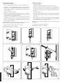
MONTAGGIO SONDA.
- Aprire il coperchio (g. 2);
- Forare con utensile appuntito il passacavo in gomma (g. 3);
- Far passare i cavi di collegamento attraverso il passacavo in
gomma (g. 4) e eettuare il collegamento elettrico alla mor-
settiera della sonda (g. 5). Il collegamento dei due cavi può
essere scambiato.
- Chiudere il coperchio (g. 6);
- Utilizzando l'apposita siringa, fornita in dotazione, cospargere
la zona di contatto della parte metallica della sonda sul tubo
con abbondante pasta conduttiva (g. 7);
- Avvicinare la sonda alla tubazione assicurandosi che la parte
metallica della sonda stessa si sovrapponga alla zona cosparsa
di pasta conduttiva e ssarla saldamente utilizzando la fascetta
fornita in dotazione (g. 8);
N.B.: utilizzando un apposito utensile è possibile, se necessario,
sbloccare la fascetta per poterla riposizionare (g. 9).
- Tagliare la parte di fascetta in eccesso (g. 10).
N.B.: diametro max tubo = DN100.
PROBE ASSEMBLY.
- Open the lid (g. 2);
- Drill the rubber cable gland with a pointed tool (g. 3);
- Pass the connection cables through the rubber cable gland (g.
4) and connect the probe electrically to the terminal block (g.
5). e two electric cables can be exchanged when being con-
nected.
- Close the lid (g. 6);
- Using the relative supplied syringe, cover the contact zone of the
metal part of the probe on the pipe with plenty of conductive
paste (g. 7);
- Move the probe towards the pipe making sure that its metal
part overlaps the area covered in conductive paste and attach it
securely using the supplied clamp (g. 8);
N.B.: if necessary, release the clamp to reposition it using a special
tool (g. 9).
- Cut any excess of the clamp (g. 10).
N.B.: max pipe diameter = DN100.
STD.000552/002

1
2 3
11
12
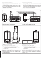
ALLACCIAMENTO ELETTRICO.
- Lunghezza massima dei cavi 25 metri (distanza caldaia - sonda
mandata impianto).
- Sezione dei cavi compresa tra 0,5 e 1,5 mm2. Il cavo deve avere
una guaina protettiva con diametro compreso tra Ø 5 ÷ 7 mm.
- In caso di caldaie collegate in Cascata Semplice, le sonde vanno
collegate alla caldaia MASTER.
SCHEMA ELETTRICO VICTRIX PRO.
Legenda:
B1 - Sonda mandata impianto (NTC)
ELECTRICAL CONNECTION.
- Maximum length of the cables is 25 metres (distance of the
boiler - system ow probe).
- Section of the cables between 0.5 and 1.5 mm e cable must
have a protective sheath with a diameter between Ø 5 and 7 mm.
- In the case of boilers connected in Simple Cascade, the probes
must be connected to the MASTER boiler.
VICTRIX PRO WIRING DIAGRAM.
Key:
B1 - System ow probe (NTC)
SCHEMA ELETTRICO VICTRIX PRO V2. VICTRIX PRO V2 WIRING DIAGRAM.
Legenda:
A38 - Scheda allacciamenti (segnali)
B1-2 - Sonda mandata impianto (NTC) (optional)
B3 - Sonda mandata bassa temperatura (NTC) (optional)
1 - BUS di comunicazione caldaie in Cascata Semplice (eseguire i
collegamenti elettrici come da schema specico)
2 - Caldaia Master
3 - Caldaia Slave / Ultima di più caldaie Slave
N.B. impostare i parametri relativi alle sonde eettivamente presenti
nell'impianto (vedi libretto istruzioni, menu "TECNICO" / "IMPO-
STAZIONI IDRAULICHE").
Key:
A38 - Terminal board (signal)
B1-2 - Common ow probe (NTC) (optional)
B3 - Flow probe (low temperature) (NTC) (optional)
1 - Boiler communication BUS in simple cascade (make the electri-
cal connections as per the specic diagram)
2 - Master boiler
3 - Slave Boiler / Last of multiple Slave boilers
N.B. set the parameters relating to the probes actually present in the
system (see instruction manual, "TECHNICIAN" / "HYDRAULIC
SETTINGS" menu).
STD.000552/002

STD.000552/002
-
 1
1
-
 2
2
-
 3
3
-
 4
4


in altre lingue
- English: VICTRIX 3.024245 User manual
Documenti correlati
Altri documenti
-
Immergas 3.023960 Manuale utente
-
-
-
-
Immergas Victrix TT Series Manuale utente
-
-
-
Immergas COD.3.023950 Istruzioni per l'uso
-
Sime Murelle Equipe 220 550 Box ErP Manuale del proprietario
-
Riello Start Condens 25 IS Installer And User Manual