
IBM xSeries 205
Type 8480
Hardware Maintenance Manual and Troubleshooting
Guide
ERserver


IBM xSeries 205
Type 8480
Hardware Maintenance Manual and Troubleshooting
Guide
ER s e r v e r

Note
Before using this information and the product it supports, read Appendix C, “Notices,” on page 155.
Eighth (January 2005)
The following paragraph does not apply to the United Kingdom or any country where such provisions are
inconsistent with local law:
INTERNATIONAL BUSINESS MACHINES CORPORATION PROVIDES THIS PUBLICATION ″AS IS″ WITHOUT
WARRANTY OF ANY KIND, EITHER EXPRESS OR IMPLIED, INCLUDING, BUT NOT LIMITED TO, THE IMPLIED
WARRANTIES OF MERCHANTABILITY OR FITNESS FOR A PARTICULAR PURPOSE. Some states do not allow
disclaimer of express or implied warranties in certain transactions, therefore, this statement may not apply to you.
This publication could include technical inaccuracies or typographical errors. Changes are periodically made to the
information herein; these changes will be incorporated in new editions of the publication. IBM may make
improvements and/or changes in the product(s) and/or the program(s) described in this publication at any time.
This publication was developed for products and services offered in the United States of America. IBM may not offer
the products, services, or features discussed in this document in other countries, and the information is subject to
change without notice. Consult your local IBM representative for information on the products, services, and features
available in your area.
Requests for technical information about IBM products should be made to your IBM reseller or IBM marketing
representative.
© Copyright International Business Machines Corporation 2002. All rights reserved.
US Government Users Restricted Rights – Use, duplication or disclosure restricted by GSA ADP Schedule Contract
with IBM Corp.

About this manual
This manual contains diagnostic information, a Symptom-to-FRU index, service
information, error codes, error messages, and configuration information for the IBM
®
Eserver
™
xSeries
®
205.
Important: The field replaceable unit (FRU) procedures are intended for trained
servicers who are familiar with IBM xSeries products. See the parts
listing in “System” on page 112 to determine if the component being
replaced is a customer replaceable unit (CRU) or a field replaceable
unit (FRU).
Important safety information
Be sure to read all caution and danger statements in this book before performing
any of the instructions.
Leia todas as instruções de cuidado e perigo antes de executar qualquer operação.
Prenez connaissance de toutes les consignes de type Attention et
Danger avant de procéder aux opérations décrites par les instructions.
Lesen Sie alle Sicherheitshinweise, bevor Sie eine Anweisung ausführen.
Accertarsi di leggere tutti gli avvisi di attenzione e di pericolo prima di effettuare
qualsiasi operazione.
Lea atentamente todas las declaraciones de precaución y peligro ante de llevar a
cabo cualquier operación.
WARNING: Handling the cord on this product or cords associated with accessories
sold with this product, will expose you to lead, a chemical known to the State of
California to cause cancer, and birth defects or other reproductive harm. Wash
hands after handling.
ADVERTENCIA: El contacto con el cable de este producto o con cables de
accesorios que se venden junto con este producto, pueden exponerle al plomo, un
elemento químico que en el estado de California de los Estados Unidos está
considerado como un causante de cancer y de defectos congénitos, además de
otros riesgos reproductivos. Lávese las manos después de usar el producto.
Online support
You can download the most current diagnostic, BIOS flash, and device driver files
from http://www.ibm.com/pc/support.
© Copyright IBM Corp. 2002 iii

iv IBM xSeries 205 Type 8480: Hardware Maintenance Manual and Troubleshooting Guide

Contents
About this manual . . . . . . . . . . . . . . . . . . . . . . . iii
Important safety information . . . . . . . . . . . . . . . . . . . . iii
Online support . . . . . . . . . . . . . . . . . . . . . . . . . iii
Chapter 1. General information . . . . . . . . . . . . . . . . . . .1
Related publications . . . . . . . . . . . . . . . . . . . . . . .1
Notices and statements in this book . . . . . . . . . . . . . . . . .2
Features and specifications . . . . . . . . . . . . . . . . . . . . .3
Server controls, LEDs, and connectors . . . . . . . . . . . . . . . .4
Server controls and LEDs . . . . . . . . . . . . . . . . . . . .4
Server connectors . . . . . . . . . . . . . . . . . . . . . . .5
Server power features . . . . . . . . . . . . . . . . . . . . . .6
Chapter 2. Configuring your server . . . . . . . . . . . . . . . . .9
Using the Configuration/Setup Utility program . . . . . . . . . . . . . .9
Starting the Configuration/Setup Utility program . . . . . . . . . . . .9
Using passwords . . . . . . . . . . . . . . . . . . . . . . .10
Enabling Broadcom NetXtreme Gigabit Ethernet Boot Agent . . . . . . . .12
Using the ServerGuide Setup and Installation CD . . . . . . . . . . . .13
ServerGuide features . . . . . . . . . . . . . . . . . . . . .13
Setup and configuration overview . . . . . . . . . . . . . . . . .14
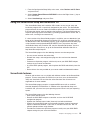
Typical operating-system installation . . . . . . . . . . . . . . . .15
Setting up or updating multiple servers . . . . . . . . . . . . . . .15
Installing your operating system without ServerGuide . . . . . . . . . .16
Configuring the Gigabit Ethernet controller . . . . . . . . . . . . . . .16
Using the SCSISelect Utility program . . . . . . . . . . . . . . . . .16
Starting the SCSISelect Utility program . . . . . . . . . . . . . . .17
SCSISelect menu choices . . . . . . . . . . . . . . . . . . . .18
Using the Boot Menu program . . . . . . . . . . . . . . . . . . .18
Chapter 3. Diagnostics . . . . . . . . . . . . . . . . . . . . .21
General checkout . . . . . . . . . . . . . . . . . . . . . . . .21
Checkout procedure . . . . . . . . . . . . . . . . . . . . . .22
Diagnostic tools overview . . . . . . . . . . . . . . . . . . . . .23
POST . . . . . . . . . . . . . . . . . . . . . . . . . . . .23
POST beep codes . . . . . . . . . . . . . . . . . . . . . .24
Error logs . . . . . . . . . . . . . . . . . . . . . . . . . .24
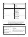
ServerGuide error symptoms . . . . . . . . . . . . . . . . . . . .24
Small computer system interface messages . . . . . . . . . . . . . .25
Diagnostic programs and error messages . . . . . . . . . . . . . . .25
Text messages . . . . . . . . . . . . . . . . . . . . . . . .26
Starting the diagnostic programs . . . . . . . . . . . . . . . . .26
Diagnostic error message tables . . . . . . . . . . . . . . . . .28
Recovering from a POST/BIOS update failure . . . . . . . . . . . . .29
Power checkout . . . . . . . . . . . . . . . . . . . . . . . .29
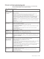
Troubleshooting the Ethernet controller . . . . . . . . . . . . . . . .30
Network connection problems . . . . . . . . . . . . . . . . . .30
Ethernet controller troubleshooting chart . . . . . . . . . . . . . .31
Ethernet controller messages . . . . . . . . . . . . . . . . . .32
Chapter 4. Installing options . . . . . . . . . . . . . . . . . . .33
System reliability considerations . . . . . . . . . . . . . . . . . .33
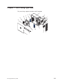
Major components of the IBM Eserver xSeries 205 Type 8480 . . . . . . .33
© Copyright IBM Corp. 2002 v

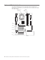
System and PCI extender boards . . . . . . . . . . . . . . . . . .34
System board internal cable connectors . . . . . . . . . . . . . . .35
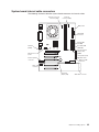
System board external connectors . . . . . . . . . . . . . . . . .36
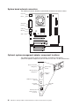
Optional system-management adapter component locations . . . . . . .36
Installation guidelines . . . . . . . . . . . . . . . . . . . . . .37
System reliability considerations . . . . . . . . . . . . . . . . .37
Handling static-sensitive devices . . . . . . . . . . . . . . . . .37
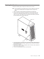
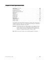
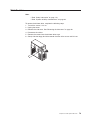
Moving the stabilizing feet . . . . . . . . . . . . . . . . . . . . .38
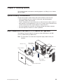
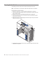
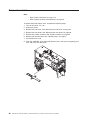
Removing the side cover . . . . . . . . . . . . . . . . . . . . .40
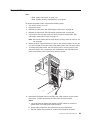
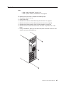
Removing the frame-support bracket . . . . . . . . . . . . . . . . .41
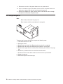
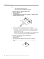
Working with adapters . . . . . . . . . . . . . . . . . . . . . .42
Adapter considerations . . . . . . . . . . . . . . . . . . . . .42
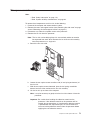
Installing an adapter . . . . . . . . . . . . . . . . . . . . . .43
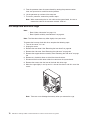
Installing a SCSI adapter . . . . . . . . . . . . . . . . . . . .45
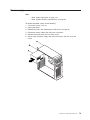
Cabling a RAID adapter or single SCSI channel using one hot-swap drive SCSI
backplane . . . . . . . . . . . . . . . . . . . . . . . . . .46
Installing internal drives . . . . . . . . . . . . . . . . . . . . . .48
Internal drive bays . . . . . . . . . . . . . . . . . . . . . .48
Preinstallation steps . . . . . . . . . . . . . . . . . . . . . .49
Power and signal cables for internal drives . . . . . . . . . . . . .50
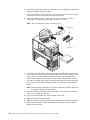
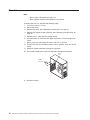
Installing a drive in bay 1, 2, 3, or 4 . . . . . . . . . . . . . . . .51
Installing a non-hot-swap hard disk drive in bay 5, 6, or 7 . . . . . . . .53
Installing a hot-swap hard disk drive in bay 5, 6, or 7 . . . . . . . . . .54
Installing memory modules . . . . . . . . . . . . . . . . . . . .57
Installing a security rope clip . . . . . . . . . . . . . . . . . . . .58
Replacing the side cover . . . . . . . . . . . . . . . . . . . . .59
Replacing the battery . . . . . . . . . . . . . . . . . . . . . .60
Connecting external options . . . . . . . . . . . . . . . . . . . .61
Video connector . . . . . . . . . . . . . . . . . . . . . . .62
Keyboard connector . . . . . . . . . . . . . . . . . . . . . .62
Mouse connector . . . . . . . . . . . . . . . . . . . . . . .62
Parallel connector . . . . . . . . . . . . . . . . . . . . . . .62
Serial connectors . . . . . . . . . . . . . . . . . . . . . . .63
Gigabit Ethernet port . . . . . . . . . . . . . . . . . . . . . .63
Universal Serial Bus (USB) connectors . . . . . . . . . . . . . . .64
Audio connectors . . . . . . . . . . . . . . . . . . . . . . .64
Optional system-management adapter ports . . . . . . . . . . . . .65
Chapter 5. Field replaceable units . . . . . . . . . . . . . . . . .67
Removing the front bezel . . . . . . . . . . . . . . . . . . . . .68
Power button . . . . . . . . . . . . . . . . . . . . . . . . .69
Hot-swap backplane . . . . . . . . . . . . . . . . . . . . . . .70
Microprocessor / fan sink . . . . . . . . . . . . . . . . . . . . .71
Hot-swap hard disk drive cage . . . . . . . . . . . . . . . . . . .72
Power supply . . . . . . . . . . . . . . . . . . . . . . . . .73
Rear fan . . . . . . . . . . . . . . . . . . . . . . . . . . .74
Extender card . . . . . . . . . . . . . . . . . . . . . . . . .75
System board . . . . . . . . . . . . . . . . . . . . . . . . .77
CD-ROM drive . . . . . . . . . . . . . . . . . . . . . . . . .78
Diskette drive . . . . . . . . . . . . . . . . . . . . . . . . .79
Bezel release latch . . . . . . . . . . . . . . . . . . . . . . .80
Top/side cover . . . . . . . . . . . . . . . . . . . . . . . . .81
Handle assembly . . . . . . . . . . . . . . . . . . . . . . . .82
Adapter retainer . . . . . . . . . . . . . . . . . . . . . . . .83
Chapter 6. Symptom-to-FRU index . . . . . . . . . . . . . . . . .85
vi IBM xSeries 205 Type 8480: Hardware Maintenance Manual and Troubleshooting Guide

Beep symptoms . . . . . . . . . . . . . . . . . . . . . . . .86
No-beep symptoms . . . . . . . . . . . . . . . . . . . . . . .87
Diagnostic panel system error LED . . . . . . . . . . . . . . . . .88
Diagnostic error codes . . . . . . . . . . . . . . . . . . . . . .90
Error symptoms . . . . . . . . . . . . . . . . . . . . . . . .95
Power-supply LED errors . . . . . . . . . . . . . . . . . . . . .96
POST error codes . . . . . . . . . . . . . . . . . . . . . . . .97
POST (ISPR) error procedures . . . . . . . . . . . . . . . . . . 100
ServeRAID error codes . . . . . . . . . . . . . . . . . . . . . 102
Service processor error codes . . . . . . . . . . . . . . . . . . . 103
SCSI error codes . . . . . . . . . . . . . . . . . . . . . . . 103
Temperature error messages . . . . . . . . . . . . . . . . . . . 104
Fan error messages . . . . . . . . . . . . . . . . . . . . . . 104
Power error messages . . . . . . . . . . . . . . . . . . . . . 105
System shutdown . . . . . . . . . . . . . . . . . . . . . . . 105
Voltage related system shutdown . . . . . . . . . . . . . . . . . 105
Temperature related system shutdown . . . . . . . . . . . . . . . 106
DASD checkout . . . . . . . . . . . . . . . . . . . . . . . . 106
Host built-in self test (BIST) . . . . . . . . . . . . . . . . . . . . 107
Bus fault messages . . . . . . . . . . . . . . . . . . . . . . . 107
Undetermined problems . . . . . . . . . . . . . . . . . . . . . 108
Problem determination tips . . . . . . . . . . . . . . . . . . . . 109
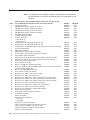
Chapter 7. Parts listing Type 8480 . . . . . . . . . . . . . . . . . 111
System . . . . . . . . . . . . . . . . . . . . . . . . . . .112
Keyboard CRUs . . . . . . . . . . . . . . . . . . . . . . . .113
Power cords . . . . . . . . . . . . . . . . . . . . . . . . .114
Appendix A. Getting help and technical assistance . . . . . . . . . .117
Before you call . . . . . . . . . . . . . . . . . . . . . . . .117
Using the documentation . . . . . . . . . . . . . . . . . . . . .117
Getting help and information from the World Wide Web . . . . . . . . .117
Software service and support . . . . . . . . . . . . . . . . . . .118
Hardware service and support . . . . . . . . . . . . . . . . . . .118
Appendix B. Related service information . . . . . . . . . . . . . .119
Safety information . . . . . . . . . . . . . . . . . . . . . . .119
General safety . . . . . . . . . . . . . . . . . . . . . . . .119
Electrical safety . . . . . . . . . . . . . . . . . . . . . . . 120
Safety inspection guide . . . . . . . . . . . . . . . . . . . . 121
Handling electrostatic discharge-sensitive devices . . . . . . . . . . 122
Grounding requirements . . . . . . . . . . . . . . . . . . . . 122
Safety notices (multilingual translations) . . . . . . . . . . . . . . 123
Appendix C. Notices . . . . . . . . . . . . . . . . . . . . . . 155
Edition notice . . . . . . . . . . . . . . . . . . . . . . . . . 155
Trademarks . . . . . . . . . . . . . . . . . . . . . . . . . . 156
Important notes . . . . . . . . . . . . . . . . . . . . . . . . 156
Product recycling and disposal . . . . . . . . . . . . . . . . . . 157
Electronic emission notices . . . . . . . . . . . . . . . . . . . . 158
Federal Communications Commission (FCC) statement . . . . . . . . 158
Industry Canada Class B emission compliance statement . . . . . . . . 158
Avis de conformité à la réglementation d’Industrie Canada . . . . . . . 158
European Union EMC Directive conformance statement . . . . . . . . 159
Power cords . . . . . . . . . . . . . . . . . . . . . . . . . 159
Contents vii

viii IBM xSeries 205 Type 8480: Hardware Maintenance Manual and Troubleshooting Guide

Chapter 1. General information
Your IBM Eserver xSeries 205 Type 8480 server is a high-performance server that
can be upgraded to a symmetric multiprocessing (SMP) server through a
microprocessor upgrade. It is ideally suited for networking environments that require
superior microprocessor performance, efficient memory management, flexibility, and
reliable data storage.
The xSeries 205 server contains several IBM X-Architecture
™
technologies, which
help increase server performance and reliability.
Your server comes with a limited warranty. If you have access to the World Wide
Web, you can obtain up-to-date information about your server model and other IBM
server products at http://www.ibm.com/pc/us/eserver/xseries/.
Your server serial number and model number are located on labels on the bottom of
the server and on the front below the bezel. You will need these numbers when you
register your server with IBM. The information label containing the serial number,
machine type, model number, and agency marks for your server is located on the
bottom of the server.
Related publications
This Hardware Maintenance Manual and Troubleshooting Guide contains
information to help you solve the problem yourself or to provide helpful information
to a service technician.
In addition to this Hardware Maintenance Manual and Troubleshooting Guide, the
following xSeries 205 Type 8480 documentation is provided with your server:
v Installation Guide
This printed publication contains setup and installation instructions.
v Rack Installation Instructions
This printed publication contains the instructions to install your server in a rack.
v Safety Book
This multilingual publication is provided in Portable Document Format (PDF) on
the IBM xSeries Documentation CD. It contains translated versions of the caution
and danger statements that appear in the documentation for your server. Each
caution and danger statement has an assigned number, which you can use to
locate the corresponding statement in your native language.
v User’s Guide
This publication is provided in PDF on the IBM xSeries Documentation CD. It
contains general information about your server, including information about
features, how to configure your server, how to use the ServerGuide
™
Setup and
Installation CD, and how to get help.
© Copyright IBM Corp. 2002 1

v Option Installation Guide
This publication is provided in PDF on the IBM xSeries Documentation CD. It
contains instructions to install, remove, and connect optional devices supported
by your server.
Depending on your server model, additional publications might be included on the
IBM xSeries Documentation CD.
Notices and statements in this book
The caution and danger statements used in this book also appear in the multilingual
Safety Information book provided on the IBM xSeries Documentation CD. Each
caution and danger statement is numbered for easy reference to the corresponding
statements in the safety book.
The following types of notices and statements are used in this book:
v Note: These notices provide important tips, guidance, or advice.
v Important: These notices provide information or advice that might help you avoid
inconvenient or problem situations.
v Attention: These notices indicate possible damage to programs, devices, or
data. An attention notice is placed just before the instruction or situation in which
damage could occur.
v Caution: These statements indicate situations that can be potentially hazardous
to you. A caution statement is placed just before the description of a potentially
hazardous procedure step or situation.
v Danger: These statements indicate situations that can be potentially lethal or
extremely hazardous to you. A danger statement is placed just before the
description of a potentially lethal or extremely hazardous procedure step or
situation.
2 IBM xSeries 205 Type 8480: Hardware Maintenance Manual and Troubleshooting Guide

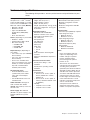
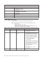
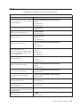
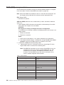
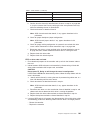
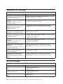
Features and specifications
The following table provides a summary of the features and specifications for your
server.
Microprocessor: Supports one
microprocessor — Intel
™
Pentium
®
4 with 128 KB, 256 KB, or 512 KB
Level-2 cache and 400 MHz or 533
MHz front side bus (FSB) Memory:
v Minimum: 128 MB
v Maximum: 2.0 GB
v Type: PC2100 266 MHz
double-density RAM (DDR)
DIMMs
v Slots: Two dual inline
Drives:
(depending on your model)
v Diskette: 1.44 MB
v Hard disk drive: IDE or SCSI
v One of the following:
– CD-ROM: IDE
– DVD-ROM: IDE
– CD-RW: IDE
Expansion
bays: (depending on
your model)
v Two 5.25-in. bays (one CD-ROM
drive installed)
v Two 3.5-in. bays (one diskette
drive installed)
v Three 3.5-in. hard disk drive
bays: hot-swap drive bays (some
models) or non-hot-swap drive
bays with a hard disk drive
installed (some models)
PCI
expansion slots:
v Three 33 MHz/32-bit on the
system board (some models
come with a SCSI adapter
installed)
v Two 33 MHz/32-bit on the PCI
extender board
Video
controller: ATI Rage XL
video controller with 16 MB
SDRAM video memory on the PCI
extender card
Power supply: One 330 watt
(90-240 V ac) power supply or one
340 watt (90-240 V ac) power
supply
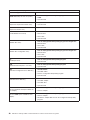
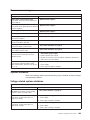
Size and weight:
v Height: 445 mm (17.5 in.)
v Depth: 498 mm (19.6 in.)
v Width: 165 mm (6.5 in.)
v Weight: approximately 19.5 kg (43 lb)
when fully configured or 15.9 kg (35
lb) minimum
Integrated
functions:
v Broadcom 5702 10/100/1000
Ethernet controller on the system
board with RJ-45 Ethernet port
v Two serial ports
v One parallel port
v Two USB ports
v Keyboard port
v Mouse port
v Audio ports
– Line out
– Line in
– Mic
v
Dual-channel bus mastering IDE
controller
v Support for IBM Remote Supervisor
Adapter
Acoustical
noise emissions:
v Sound power, idling: 5.1 bel
maximum
v Sound power, operating: 5.3 bel
maximum
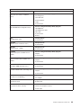
Environment:
v Air temperature:
– Server on: 10° to 35°C (50.0° to
95.0°F). Altitude: 0 to 2133 m
(6998.0.7 ft)
– Server off: 10° to 43°C (50.0° to
109.4°F). Maximum altitude: 2133
m (6998.0 ft)
v
Humidity:
– Computer on: 8% to 80%
– Computer off: 8% to 80%
Heat output: Approximate heat output
in British thermal units (Btu) per hour
v Minimum configuration: 341 Btu
(100 watts)
v Maximum configuration: 1604 Btu
(470 watts)
Electrical
input:
v Sine-wave input (50-60 Hz) required
v Input voltage low range:
– Minimum: 90 V ac
– Maximum: 137 V ac
v
Input voltage high range:
– Minimum: 180 V ac
– Maximum: 265 V ac
v
Input kilovolt-amperes (kVA)
approximately:
– Minimum: 0.095 kVA
– Maximum: 0.470 kVA
Notes:
1. Power consumption and heat
output vary depending on the
number and type of optional
features installed and the
power-management optional
features in use.
2. These levels were measured in
controlled acoustical environments
according to the procedures
specified by the American National
Standards Institute (ANSI) S12.10
and ISO 7779 and are reported in
accordance with ISO 9296. Actual
sound-pressure levels in a given
location might exceed the average
values stated because of room
reflections and other nearby noise
sources. The declared
sound-power levels indicate an
upper limit, below which a large
number of computers will operate.
Chapter 1. General information 3

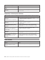
Server controls, LEDs, and connectors
This section describes the controls, light-emitting diodes (LEDs), and connectors on
your server.
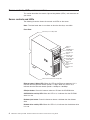
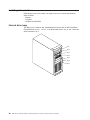
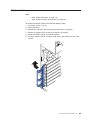
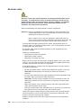
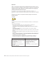
Server controls and LEDs
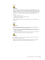
The following illustration shows the controls and LEDs on the server.
Note: The front bezel door is not shown so that the drive bays are visible.
Front View:
CD-eject
button
CD-ROM drive
activity LED
Diskette-eject
button
Hard disk drive
activity LED
Power-on
LED
Power-control
button
System error
LED
Diskette drive
activity LED
Ethernet speed 1 Gbps LED
Ethernet transmit/receive activity LED
Ethernet speed 1 Gbps LED: When this LED on the Ethernet connector is lit, it
indicates that the Ethernet network speed is 1 Gbps. When this LED is off, it
indicates that the Ethernet network speed is 10 Mbps or 100 Mbps.
CD-eject button: Press this button to release a CD from the CD-ROM drive.
CD-ROM drive activity LED: When this LED is lit, it indicates that the CD-ROM
drive is in use.
Diskette-eject button: Press this button to release a diskette from the diskette
drive.
Diskette drive activity LED: When this LED is lit, it indicates that the diskette drive
is in use.
4 IBM xSeries 205 Type 8480: Hardware Maintenance Manual and Troubleshooting Guide

Hard disk drive activity LED: When this LED is flashing, it indicates that the hard
disk drive is in use.
Power-on LED: When this LED is lit, it indicates that the server is turned on.
Power-control button: Press this button to turn the server on and off manually.
Ethernet transmit/receive activity LED: When this LED on the Ethernet connector
is lit, it indicates that there is activity between the server and the network.
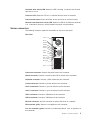
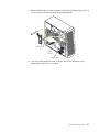
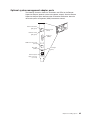
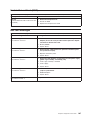
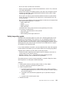
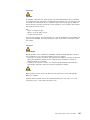
Server connectors
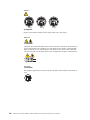
The following illustration shows the connectors on the rear of the server.
Rear View:
Power cord
Mouse
Keyboard
Parallel
Serial 1
Serial 2
USB 2
USB 1
Mic (pink)
Line in (blue)
Line out (green)
Ethernet
Video
1
1
2
2
Power-cord connector: Connect the power cord to this connector.
Mouse connector: Connect a mouse or other PS/2
®
device to this connector.
Keyboard connector: Connect a PS/2 keyboard to this connector.
Parallel connector: Connect a parallel device to this connector.
Serial 2 connector: Connect a 9-pin serial device to this connector.
Serial 1 connector: Connect a 9-pin serial device to this connector
USB 1 connector: Connect a USB device to this connector.
USB 2 connector: Connect a USB device to this connector.
Ethernet connector: Use this connector to connect the server to a network.
Mic connector (pink): Connect a microphone to this connector.
Line out connector (green): Connect an audio output device, such as speakers, to
this connector.
Chapter 1. General information 5

Line in connector (blue): Connect an audio input device, such as a stereo, to this
connector.
Video connector: Connect a monitor to this connector.
If you have an optional Remote Supervisor Adapter (system-management adapter)
installed in PCI slot 1, your server has additional connectors and LEDs. See the
Option Installation Guide for more information about these connectors and LEDs.
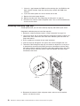
Server power features
When you connect the server to an ac power source, the server goes into Standby
mode. After approximately 20 seconds, the power-control button becomes active,
and you can turn on the server and start the operating system by pressing the
power-control button. The following section describes other ways in which the
server can be turned on.
A power-control-button shield comes with your server. You can install this
disk-shaped shield to prevent the server from being turned off accidentally.
Turning on the server
After the server is connected to an ac power source, it can be turned on in any of
the following ways:
v You can press the power-control button.
v If a power failure occurs while the server is turned on, the server will restart
automatically when power is restored.
v If your operating system supports the system-management software for an
optional Remote Supervisor Adapter, the system-management software can turn
on the server.
v If your operating system supports the Wake on LAN
®
feature, the Wake on LAN
feature can turn on the server.
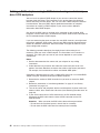
Turning off the server
Some operating systems require an orderly shutdown before you turn off the server.
See your operating-system documentation for information about shutting down the
operating system.
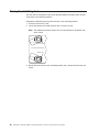
Statement 5:
CAUTION:
The power control button on the device and the power switch on the power
supply do not turn off the electrical current supplied to the device. The device
also might have more than one power cord. To remove all electrical current
from the device, ensure that all power cords are disconnected from the power
source.
1
2
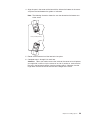
The server can be turned off in any of the following ways:
6 IBM xSeries 205 Type 8480: Hardware Maintenance Manual and Troubleshooting Guide

v You can press the power-control button to start an orderly shutdown of the
operating system, if your operating system supports this feature, and turn off the
server.
v If the operating system stops functioning, you can press and hold the
power-control button for more than 4 seconds to turn off the server.
v If the Wake on LAN feature turned on the server, the Wake on LAN feature can
turn off the server.
v You can remove all power from the computer by disconnecting the server from
the ac power source.
Standby mode
When the server is connected to an ac power source but has not been turned on, it
is in Standby mode. When the server is in Standby mode, the operating system is
not running, and all core logic except for the service processor is shut down. The
power-on LED flashes to indicate that the server is in Standby mode. The server
can respond to requests from the service processor, such as a remote request to
turn on the server.
To put the server into Standby mode when the server is turned on, shut down the
operating system (see your operating-system documentation), and press the
power-control button.
You can also put the server into Standby mode through a request from the service
processor.
Chapter 1. General information 7

8 IBM xSeries 205 Type 8480: Hardware Maintenance Manual and Troubleshooting Guide

Chapter 2. Configuring your server
You can use the following configuration programs to customize your server
hardware:
v Configuration/Setup Utility program
The Configuration/Setup Utility program is part of the basic input/output system
(BIOS) code that comes with your server. You can use this program to configure
serial port assignments, change interrupt request (IRQ) settings, change the
device startup sequence, set the date and time, and set passwords.
v Broadcom NetXtreme Gigabit Ethernet Boot Agent
The Broadcom NetXtreme Gigabit Ethernet Boot Agent is part of the BIOS code
that comes with your server. You can enable the Broadcom NetXtreme Gigabit
Ethernet Boot Agent in the Configuration/Setup Utility program. The Broadcom
NetXtreme Gigabit Ethernet Boot Agent enables you to configure the network as
a startable device and customize where the network option appears in your
startup sequence.
v ServerGuide Setup and Installation CD
The ServerGuide Setup and Installation CD provides software setup tools and
installation tools that are specifically designed for your IBM server. Use this CD
during the initial installation of your server to configure basic hardware features
and to simplify your network operating system (NOS) installation. See “Using the
ServerGuide Setup and Installation CD” on page 13 for more information.
v Ethernet controller configuration process
To configure the Ethernet controller, see “Configuring the Gigabit Ethernet
controller” on page 16.
v SCSISelect Utility program (some models)
If your server comes with a SCSI controller on the PCI extender card, you can
use the SCSISelect Utility program to configure devices that are attached to the
SCSI controller. Use this program to change default values, resolve configuration
conflicts, and perform a low-level format on a SCSI hard disk drive.
v Boot Menu program
The Boot Menu program is part of the BIOS code that comes with your server.
You can use the Boot Menu program to change startup sequence for one startup
session without changing settings in the Configuration/Setup Utility program.
Using the Configuration/Setup Utility program
This section provides the instructions for starting the Configuration/Setup Utility
program and descriptions of the menu choices that are available.
Starting the Configuration/Setup Utility program
The Configuration/Setup Utility program starts automatically when POST detects
that newly installed or removed hardware is not reflected in your current
configuration. A power-on-self-test (POST) error message is displayed. See the
Hardware Maintenance Manual and Troubleshooting Guide for details about the
POST error messages.
© Copyright IBM Corp. 2002 9

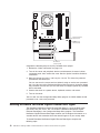
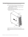
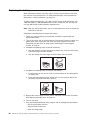
Complete the following steps to start the Configuration/Setup Utility program:
1. Turn on the server and watch the monitor screen. If your server is already on
when you start this procedure, you must shut down the operating system, turn
off the server, wait a few seconds until all in-use LEDs go off, and restart the
server. Do not use Ctrl+Alt+Del to restart the server.
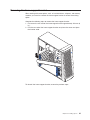
2. When the message Press F1 for Configuration/Setup, Press F12 for Boot
Menu appears at the bottom of the screen during startup, press F1. (This prompt
appears on the screen for only a few seconds. You must press F1 quickly.)
Note: If you have set both administrator and user passwords, you must type
the administrator password to access the full Configuration/Setup Utility
menu.
3. Follow the instructions that appear on the screen.
Use
the Up Arrow (↑)and Down Arrow (↓) keys to select menu choices in any
Configuration/Setup Utility menu. Some menu choices provide information only.
Some menu choices show fields that you can change. These fields are enclosed by
square brackets. You can change the settings in these fields by using Left Arrow (←)
and Right Arrow (→) keys to change the settings, or you can type information in the
field.
To reload the current setting for a menu item, press F9. To reload the default setting
for a menu item, press F10.
Using passwords
The System Security choice appears only on the full Configuration/Setup Utility
menu. After you select this choice, you can implement an administrator password.
The administrator password provides access to all choices on the
Configuration/Setup Utility main menu. You can set, change, or delete the
administrator password.
The administrator password has the following features:
v No password is required to start the system.
v Type the password to access the Configuration/Setup Utility program.
v All choices are available on the Configuration/Setup Utility main menu.
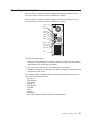
Complete
the following steps to set an administrator password:
1. From the Configuration/Setup Utility main menu, select System Security and
press Enter.
2. Select Administrator Password and press the Right Arrow (→) key.
3. Type the password you want to set in the Enter Password field and press
Enter.
4. Type the password again in the Enter Password again field and press Enter.
5. Press Enter to Set or Change Password. The setting in the Administrator
Password field changes to Present.
6. Press Esc until you return to the main menu.
7. Select Save Settings and Press Enter.
After
you have set an administrator password, you can then set a user password to
authorize a user to operate the server. You must set an administrator password to
set a user password.
10 IBM xSeries 205 Type 8480: Hardware Maintenance Manual and Troubleshooting Guide
La pagina si sta caricando...
La pagina si sta caricando...
La pagina si sta caricando...
La pagina si sta caricando...
La pagina si sta caricando...
La pagina si sta caricando...
La pagina si sta caricando...
La pagina si sta caricando...
La pagina si sta caricando...
La pagina si sta caricando...
La pagina si sta caricando...
La pagina si sta caricando...
La pagina si sta caricando...
La pagina si sta caricando...
La pagina si sta caricando...
La pagina si sta caricando...
La pagina si sta caricando...
La pagina si sta caricando...
La pagina si sta caricando...
La pagina si sta caricando...
La pagina si sta caricando...
La pagina si sta caricando...
La pagina si sta caricando...
La pagina si sta caricando...
La pagina si sta caricando...
La pagina si sta caricando...
La pagina si sta caricando...
La pagina si sta caricando...
La pagina si sta caricando...
La pagina si sta caricando...
La pagina si sta caricando...
La pagina si sta caricando...
La pagina si sta caricando...
La pagina si sta caricando...
La pagina si sta caricando...
La pagina si sta caricando...
La pagina si sta caricando...
La pagina si sta caricando...
La pagina si sta caricando...
La pagina si sta caricando...
La pagina si sta caricando...
La pagina si sta caricando...
La pagina si sta caricando...
La pagina si sta caricando...
La pagina si sta caricando...
La pagina si sta caricando...
La pagina si sta caricando...
La pagina si sta caricando...
La pagina si sta caricando...
La pagina si sta caricando...
La pagina si sta caricando...
La pagina si sta caricando...
La pagina si sta caricando...
La pagina si sta caricando...
La pagina si sta caricando...
La pagina si sta caricando...
La pagina si sta caricando...
La pagina si sta caricando...
La pagina si sta caricando...
La pagina si sta caricando...
La pagina si sta caricando...
La pagina si sta caricando...
La pagina si sta caricando...
La pagina si sta caricando...
La pagina si sta caricando...
La pagina si sta caricando...
La pagina si sta caricando...
La pagina si sta caricando...
La pagina si sta caricando...
La pagina si sta caricando...
La pagina si sta caricando...
La pagina si sta caricando...
La pagina si sta caricando...
La pagina si sta caricando...
La pagina si sta caricando...
La pagina si sta caricando...
La pagina si sta caricando...
La pagina si sta caricando...
La pagina si sta caricando...
La pagina si sta caricando...
La pagina si sta caricando...
La pagina si sta caricando...
La pagina si sta caricando...
La pagina si sta caricando...
La pagina si sta caricando...
La pagina si sta caricando...
La pagina si sta caricando...
La pagina si sta caricando...
La pagina si sta caricando...
La pagina si sta caricando...
La pagina si sta caricando...
La pagina si sta caricando...
La pagina si sta caricando...
La pagina si sta caricando...
La pagina si sta caricando...
La pagina si sta caricando...
La pagina si sta caricando...
La pagina si sta caricando...
La pagina si sta caricando...
La pagina si sta caricando...
La pagina si sta caricando...
La pagina si sta caricando...
La pagina si sta caricando...
La pagina si sta caricando...
La pagina si sta caricando...
La pagina si sta caricando...
La pagina si sta caricando...
La pagina si sta caricando...
La pagina si sta caricando...
La pagina si sta caricando...
La pagina si sta caricando...
La pagina si sta caricando...
La pagina si sta caricando...
La pagina si sta caricando...
La pagina si sta caricando...
La pagina si sta caricando...
La pagina si sta caricando...
La pagina si sta caricando...
La pagina si sta caricando...
La pagina si sta caricando...
La pagina si sta caricando...
La pagina si sta caricando...
La pagina si sta caricando...
La pagina si sta caricando...
La pagina si sta caricando...
La pagina si sta caricando...
La pagina si sta caricando...
La pagina si sta caricando...
La pagina si sta caricando...
La pagina si sta caricando...
La pagina si sta caricando...
La pagina si sta caricando...
La pagina si sta caricando...
La pagina si sta caricando...
La pagina si sta caricando...
La pagina si sta caricando...
La pagina si sta caricando...
La pagina si sta caricando...
La pagina si sta caricando...
La pagina si sta caricando...
La pagina si sta caricando...
La pagina si sta caricando...
La pagina si sta caricando...
La pagina si sta caricando...
La pagina si sta caricando...
La pagina si sta caricando...
La pagina si sta caricando...
La pagina si sta caricando...
La pagina si sta caricando...
La pagina si sta caricando...
La pagina si sta caricando...
La pagina si sta caricando...
La pagina si sta caricando...
La pagina si sta caricando...
-
 1
1
-
 2
2
-
 3
3
-
 4
4
-
 5
5
-
 6
6
-
 7
7
-
 8
8
-
 9
9
-
 10
10
-
 11
11
-
 12
12
-
 13
13
-
 14
14
-
 15
15
-
 16
16
-
 17
17
-
 18
18
-
 19
19
-
 20
20
-
 21
21
-
 22
22
-
 23
23
-
 24
24
-
 25
25
-
 26
26
-
 27
27
-
 28
28
-
 29
29
-
 30
30
-
 31
31
-
 32
32
-
 33
33
-
 34
34
-
 35
35
-
 36
36
-
 37
37
-
 38
38
-
 39
39
-
 40
40
-
 41
41
-
 42
42
-
 43
43
-
 44
44
-
 45
45
-
 46
46
-
 47
47
-
 48
48
-
 49
49
-
 50
50
-
 51
51
-
 52
52
-
 53
53
-
 54
54
-
 55
55
-
 56
56
-
 57
57
-
 58
58
-
 59
59
-
 60
60
-
 61
61
-
 62
62
-
 63
63
-
 64
64
-
 65
65
-
 66
66
-
 67
67
-
 68
68
-
 69
69
-
 70
70
-
 71
71
-
 72
72
-
 73
73
-
 74
74
-
 75
75
-
 76
76
-
 77
77
-
 78
78
-
 79
79
-
 80
80
-
 81
81
-
 82
82
-
 83
83
-
 84
84
-
 85
85
-
 86
86
-
 87
87
-
 88
88
-
 89
89
-
 90
90
-
 91
91
-
 92
92
-
 93
93
-
 94
94
-
 95
95
-
 96
96
-
 97
97
-
 98
98
-
 99
99
-
 100
100
-
 101
101
-
 102
102
-
 103
103
-
 104
104
-
 105
105
-
 106
106
-
 107
107
-
 108
108
-
 109
109
-
 110
110
-
 111
111
-
 112
112
-
 113
113
-
 114
114
-
 115
115
-
 116
116
-
 117
117
-
 118
118
-
 119
119
-
 120
120
-
 121
121
-
 122
122
-
 123
123
-
 124
124
-
 125
125
-
 126
126
-
 127
127
-
 128
128
-
 129
129
-
 130
130
-
 131
131
-
 132
132
-
 133
133
-
 134
134
-
 135
135
-
 136
136
-
 137
137
-
 138
138
-
 139
139
-
 140
140
-
 141
141
-
 142
142
-
 143
143
-
 144
144
-
 145
145
-
 146
146
-
 147
147
-
 148
148
-
 149
149
-
 150
150
-
 151
151
-
 152
152
-
 153
153
-
 154
154
-
 155
155
-
 156
156
-
 157
157
-
 158
158
-
 159
159
-
 160
160
-
 161
161
-
 162
162
-
 163
163
-
 164
164
-
 165
165
-
 166
166
-
 167
167
-
 168
168
-
 169
169
-
 170
170
-
 171
171
-
 172
172
-
 173
173
-
 174
174


IBM 8480 - Eserver xSeries 205 Maintenance And Troubleshooting Manual
- Tipo
- Maintenance And Troubleshooting Manual
- Questo manuale è adatto anche per
in altre lingue
- English: IBM 8480 - Eserver xSeries 205
Documenti correlati
Altri documenti
-
Lenovo 6290 Hardware Maintenance Manual
-
DeLOCK 84300 Scheda dati
-
Lenovo Aptiva 2274 Hardware Maintenance Manual
-
-
Quantum Scalar Key Manager Manuale utente
-
Intel SRKA4 - Server Platform - 0 MB RAM Manuale utente
-
-
Lenovo ThinkCentre M51e Quick Reference Manual
-
Gateway E-1600 System Manual
-