
Order Number: 309247-004US
Intel NetStructure
®
MPCMM0002
Chassis Management Module
Hardware Technical Product Specification
July 2007

Intel NetStructure
®
MPCMM0002 Chassis Management Module
Hardware TPS July 2007
2 Order Number: 309247-004US
Legal Lines and Disclaimers
INFORMATION IN THIS DOCUMENT IS PROVIDED IN CONNECTION WITH INTEL® PRODUCTS. NO LICENSE, EXPRESS OR IMPLIED, BY ESTOPPEL OR
OTHERWISE, TO ANY INTELLECTUAL PROPERTY RIGHTS IS GRANTED BY THIS DOCUMENT. EXCEPT AS PROVIDED IN INTEL’S TERMS AND CONDITIONS
OF SALE FOR SUCH PRODUCTS, INTEL ASSUMES NO LIABILITY WHATSOEVER, AND INTEL DISCLAIMS ANY EXPRESS OR IMPLIED WARRANTY, RELATING
TO SALE AND/OR USE OF INTEL PRODUCTS INCLUDING LIABILITY OR WARRANTIES RELATING TO FITNESS FOR A PARTICULAR PURPOSE,
MERCHANTABILITY, OR INFRINGEMENT OF ANY PATENT, COPYRIGHT OR OTHER INTELLECTUAL PROPERTY RIGHT. Intel products are not intended for
use in medical, life saving, life sustaining, critical control or safety systems, or in nuclear facility applications.
Intel may make changes to specifications and product descriptions at any time, without notice. Designers must not rely on the absence or characteristics
of any features or instructions marked “reserved” or “undefined.” Intel reserves these for future definition and shall have no responsibility whatsoever for
conflicts or incompatibilities arising from future changes to them. The information here is subject to change without notice. Do not finalize a design with
this information.
The products described in this document may contain design defects or errors known as errata which may cause the product to deviate from published
specifications. Current characterized errata are available on request.
Contact your local Intel sales office or your distributor to obtain the latest specifications and before placing your product order.
Copies of documents which have an order number and are referenced in this document, or other Intel literature, may be obtained by calling 1-800-548-
4725, or by visiting Intel’s Web Site.
Intel processor numbers are not a measure of performance. Processor numbers differentiate features within each processor family, not across different
processor families. See http://www.intel.com/products/processor_number for details.
BunnyPeople, Celeron, Celeron Inside, Centrino, Centrino logo, Core Inside, FlashFile, i960, InstantIP, Intel, Intel logo, Intel386, Intel486, Intel740,
IntelDX2, IntelDX4, IntelSX2, Intel Core, Intel Inside, Intel Inside logo, Intel. Leap ahead., Intel. Leap ahead. logo, Intel NetBurst, Intel NetMerge, Intel
NetStructure, Intel SingleDriver, Intel SpeedStep, Intel StrataFlash, Intel Viiv, Intel vPro, Intel XScale, Itanium, Itanium Inside, MCS, MMX, Oplus,
OverDrive, PDCharm, Pentium, Pentium Inside, skoool, Sound Mark, The Journey Inside, VTune, Xeon, and Xeon Inside are trademarks of Intel
Corporation in the U.S. and other countries.
*Other names and brands may be claimed as the property of others.
Copyright © 2007, Intel Corporation. All rights reserved.

Intel NetStructure
®
MPCMM0002 Chassis Management Module
July 2007 Hardware TPS
Order Number: 309247-004US 3
Contents—MPCMM0002 CMM
Contents
1.0 Document Organization.............................................................................................8
1.1 Acronyms and Terms.........................................................................................10
2.0 Introduction............................................................................................................11
2.1 Architecture Specification ...................................................................................11
2.2 User Documentation..........................................................................................11
2.3 Product Definition..............................................................................................11
3.0 Getting Started........................................................................................................13
3.1 Installing the CMM.............................................................................................13
4.0 Module Components ................................................................................................15
4.1 Block Diagram ..................................................................................................15
4.2 Intel® 80321 Processor ..................................................................................... 17
4.3 Memory ...........................................................................................................19
4.4 Ethernet ..........................................................................................................19
4.5 Serial Port UARTs..............................................................................................19
4.6 FPGA...............................................................................................................20
4.7 Redundancy and Hot Swap CPLD.........................................................................20
4.8 Watchdog Timer................................................................................................20
4.9 Real-Time Clock................................................................................................20
4.10 ADM1026 Controller ..........................................................................................21
4.11 Hot Swap Controller...........................................................................................21
4.12 Ride-Through Support........................................................................................21
4.13 IPMB Isolation Logic ..........................................................................................21
5.0 Mechanical Information...........................................................................................24
5.1 Dimensions ......................................................................................................24
5.2 Front Panel Hardware ........................................................................................26
5.3 Rear Connector Placement..................................................................................27
5.4 ESD Discharge Strip ..........................................................................................27
6.0 Backplane Considerations........................................................................................28
6.1 IPMB Routing....................................................................................................28
6.2 CMM Power ......................................................................................................28
7.0 Rear Connections ....................................................................................................32
7.1 CMM Connector Pinouts......................................................................................32
7.2 Guide Post........................................................................................................41
7.3 CMM Redundancy..............................................................................................41
8.0 Chassis Data Modules (CDMs)..................................................................................43
8.1 CDM Overview ..................................................................................................43
8.2 CDM LED..........................................................................................................43
8.3 CDM Management .............................................................................................43
8.4 CDM Power.......................................................................................................44
8.5 CDM Redundancy ..............................................................................................44
9.0 Front Panel..............................................................................................................45
9.1 Serial Port Pinouts.............................................................................................45
9.2 Ethernet Port Pinouts.........................................................................................47
9.3 Telco Alarm Connector.......................................................................................48
9.4 Alarm Quiet Switch............................................................................................51
9.5 LEDs................................................................................................................52
10.0 Grounding Considerations .......................................................................................54

MPCMM0002 CMM—Contents
Intel NetStructure
®
MPCMM0002 Chassis Management Module
Hardware TPS July 2007
4 Order Number: 309247-004US
10.1 ESD Discharge Protection....................................................................................54
10.2 Chassis Ground and Logic Ground........................................................................54
11.0 Thermals..................................................................................................................55
11.1 Processor Heat Sink...........................................................................................55
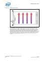
11.2 Module Orientation.............................................................................................55
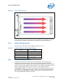
11.3 Module Airflow Path ...........................................................................................55
11.4 Airflow Requirements .........................................................................................57
11.5 Board Resistance Curve......................................................................................57
11.6 Thermal Sensors................................................................................................58
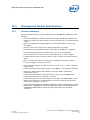
12.0 Management Module Specifications..........................................................................59
12.1 Feature Summary..............................................................................................59
12.2 Dimensions and Weight ......................................................................................60
12.3 Environmental Characteristics .............................................................................60
12.4 Product Reliability Estimate.................................................................................60
12.5 Agency Certifications..........................................................................................61
13.0 Guidelines for Third Party Chassis Vendors..............................................................62
13.1 High Level Design..............................................................................................62
13.2 IPMB Buses.......................................................................................................63
13.3 GPIO Pins.........................................................................................................66
13.4 Interfacing FRUs to the CMM ...............................................................................67
13.5 Intelligent FRUs.................................................................................................68
13.6 Non-Intelligent FRUs with I2C* Support................................................................68
13.7 Non-Intelligent FRUs without I2C Support .............................................................69
13.8 FRU Data Storage for Non-Intelligent Devices........................................................69
13.9 Controllers and I/O Ports for Non-Intelligent Devices..............................................70
13.10 Temperature Sensors Fronted by the CMM ............................................................70
13.11 Related Documents............................................................................................70
14.0 Warranty Information..............................................................................................71
14.1 Intel NetStructure
®
Compute Boards & Platform Products Limited Warranty ..............71
14.2 Returning a Defective Product (RMA)....................................................................71
14.3 For the Americas ...............................................................................................72
15.0 Customer Support....................................................................................................74
15.1 Customer Support..............................................................................................74
15.2 Technical Support and Return for Service Assistance ..............................................74
15.3 Sales Assistance................................................................................................74
15.4 Product Code Summary......................................................................................74
16.0 Certifications ...........................................................................................................75
16.1 Material Declaration Data Sheet...........................................................................75
17.0 Agency Information .................................................................................................77
17.1 North America (FCC Class A)...............................................................................77
17.2 Canada – Industry Canada (ICES-003 Class A) (English and French-translated below) 77
17.3 Safety Instructions (English and French-translated below).......................................78
17.4 Taiwan Class A Warning Statement ......................................................................78
17.5 Japan VCCI Class A............................................................................................79
17.6 Korean Class A..................................................................................................79
17.7 Australia, New Zealand.......................................................................................79
18.0 Safety Warnings ......................................................................................................80
18.1 Mesures de Sécurité...........................................................................................81
18.2 Sicherheitshinweise............................................................................................83
18.3 Norme di Sicurezza............................................................................................85

Intel NetStructure
®
MPCMM0002 Chassis Management Module
July 2007 Hardware TPS
Order Number: 309247-004US 5
Contents—MPCMM0002 CMM
18.4 Instrucciones de Seguridad.................................................................................87
18.5 Chinese Safety Warning .....................................................................................89
Figures
1 Top View of the Intel NetStructure
®
MPCMM0002 CMM ................................................. 13
2 CMM Block Diagram .................................................................................................15
3 CMM Top View Layout...............................................................................................16
4 Intel® 80321 Processor Internal Block Diagram ...........................................................17
5 IPMB Dual Star Isolation ...........................................................................................22
6 Dual Bus IPMB Isolation............................................................................................23
7 CMM Component Side 1 Dimensions...........................................................................24
8 CMM Backing Plate Dimensions..................................................................................25
9 CMM Side View Dimensions .......................................................................................26
10 CMM ESD Strip Electrical Definition.............................................................................27
11 Power System Block Diagram ....................................................................................29
12 CDM Power Input.....................................................................................................30
13 Ethernet Port Poaching .............................................................................................31
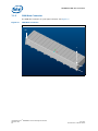
14 CMM Power Connector ..............................................................................................32
15 CMM Data Connector................................................................................................36
16 Cross-Connected CMM Signals ...................................................................................41
17 Guide Post to Backplane ...........................................................................................41
18 Chassis Data Module I2C Routing...............................................................................43
19 CMM Front Panel......................................................................................................45
20 Serial Port RJ-45 Connector.......................................................................................46
21 Serial Port RJ-45 Cabling...........................................................................................46
22 Ethernet Port RJ-45 Connector Front View...................................................................47
23 DB-15 Telco Alarm Connector....................................................................................48
24 Telco Alarm Contact Wiring for Dual Connectors...........................................................49
25 Failure Scenario with Dual Telco Alarm Connectors .......................................................50
26 Parallel Inputs to Telco Alarm Connectors....................................................................50
27 Cascaded Telco Alarm Cables.....................................................................................51
28 CMM Front Panel with Labels .....................................................................................52
29 CMM Heat Sink........................................................................................................55
30 Side-to-Side Air Flow................................................................................................56
31 Front-to-Back Air Flow..............................................................................................57
32 High Level CMM Design.............................................................................................62
33 I/O Signals of the CMM.............................................................................................63
34 Radial Bus Topology .................................................................................................65
35 Shared Bus Topology................................................................................................66
36 FRU That Uses the ADM1026 .....................................................................................69
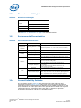
Tables
1 Acronyms and Terms................................................................................................10
2 Processor Features...................................................................................................17
3 FPGA Features.........................................................................................................20
4 Voltage Usage .........................................................................................................29
5 Chassis Elements Directly Driven by CMM Hardware .....................................................31
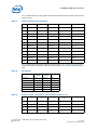
6 Power Connector Pinouts...........................................................................................33
7 Power Connector Pinouts Matrix.................................................................................34
8 Pin Staging .............................................................................................................34
9 Power Connector Receptacle Pin Placement .................................................................34
10 Power Connector Header Pin Placement ......................................................................35
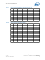
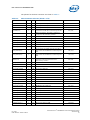
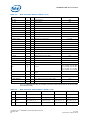
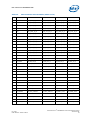
11 Data Connector Pinouts ............................................................................................37
12 Data Connector Pinouts Matrix...................................................................................38
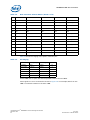
13 Pin Staging .............................................................................................................40

MPCMM0002 CMM—Contents
Intel NetStructure
®
MPCMM0002 Chassis Management Module
Hardware TPS July 2007
6 Order Number: 309247-004US
14 CDM Health LED States .............................................................................................43
15 RTM Serial Port Pinout...............................................................................................46
16 Ethernet Port Pinouts ................................................................................................47
17 Ethernet Port LED States...........................................................................................48
18 Telco Alarm Pinout....................................................................................................49
19 Ganged Telco Alarm Cable Pinouts with Cabling............................................................51
20 CDM Health LED States .............................................................................................52
21 CMM Health LED States.............................................................................................53
22 CMM Hot Swap LED States.........................................................................................53
23 Typical Airflow and Cooling Requirements ....................................................................57
24 Airflow Guidelines.....................................................................................................58
25 Dimensions and Weight.............................................................................................60
26 Environmental Characteristics ....................................................................................60
27 Reliability Estimate Data............................................................................................61
28 Physical Bus Number Mapping....................................................................................64
29 Related Documents...................................................................................................70
30 MPCMM0002 Product Code Summary ..........................................................................74

Intel NetStructure
®
MPCMM0002 Chassis Management Module
July 2007 Hardware TPS
Order Number: 309247-004US 7
Revision History—MPCMM0002 CMM
Revision History
Date Revision Description
July 2007 004 CMM drawings updated
July 2007 003 Failure Rate and MTBF values updated.
May 2007 002
Quick Start section updated with new CMM removal procedure.
CMM dimension drawings updated.
April 2006 001 Initial release of this document.

MPCMM0002 CMM—Document Organization
Intel NetStructure
®
MPCMM0002 Chassis Management Module
Hardware TPS July 2007
8 Order Number: 309247-004US
1.0 Document Organization
This document describes the operation and use of the Intel NetStructure
®
MPCMM0002
CMM.
The following topics are covered in this document.
Chapter 2.0, “Introduction” introduces the key features of the MPCMM0002 CMM. This
chapter includes a product definition and a list of product features.
Chapter 3.0, “Getting Started” provides installation and setup information for the
MPCMM0002 CMM. This chapter should be read before using the management module.
Chapter 4.0, “Module Components” describes the major components of the CMM and
how the components are interconnected.
Chapter 5.0, “Mechanical Information” provides information on the critical dimensions
of the CMM.
Chapter 6.0, “Backplane Considerations” identifies the IPMB routing requirements,
power distribution options, and Ethernet routing information for chassis designers to
build the MPCMM0002 CMM into their shelves.
Chapter 7.0, “Rear Connections” details the pinouts for the two connectors that
interface with a backplane or coplanar mating board.
Chapter 8.0, “Chassis Data Modules (CDMs)” provides information on how the CMM
accesses the Chassis Data Module (shelf FRU repository).
Chapter 9.0, “Front Panel” details the cable connections and LEDs on the CMM’s front
panel
Chapter 10.0, “Grounding Considerations” provides information on grounding jumpers
and ESD discharge features.
Chapter 11.0, “Thermals” provides information on the cooling requirements for the
CMM.
Chapter 12.0, “Management Module Specifications” contains the electrical,
environmental, and mechanical specifications for the CMM.
Chapter 13.0, “Guidelines for Third Party Chassis Vendors” provides a high-level design
of the MPCMM0002 CMM to help third party chassis vendors incorporate it into their
chassis.
Chapter 14.0, “Warranty Information” defines the warranty for the MPCMM0002 CMM.
Chapter 15.0, “Customer Support” provides information on reaching Intel customer
support.
Chapter 16.0, “Certifications” lists the various applicable product certifications of the
CMM.

Intel NetStructure
®
MPCMM0002 Chassis Management Module
July 2007 Hardware TPS
Order Number: 309247-004US 9
Document Organization—MPCMM0002 CMM
Chapter 17.0, “Agency Information” contains notices from various certifying agencies.
Chapter 18.0, “Safety Warnings” lists important safety warnings in various languages.
1.1 Acronyms and Terms
The following special acronyms and terms are used in this specification:
Table 1. Acronyms and Terms
Acronym/Term Meaning
Board Front Board as defined in PICMG 3.0 specification
CDM Chassis Data Module
CFM Cubic Feet per Minute
Chassis Physical structure containing boards, backplane, PEMs, etc,; same as shelf
CMM Chassis Management Module
COM
Common connection [used with relay contacts in Section 9.3, “Telco Alarm
Connector” on page 48.
Component Side 1 Primary side of PCB, used for synergy with PICMG 3.0 terminology
Component Side 2 Secondary side of PCB
EMI Electromagnetic Interference
ESD Electrostatic Discharge
ETSI European Telecommunications Standards Institute
Frame Structure in which chassis is mounted; could be enclosed or open; same as rack
FRU Field Replaceable Unit
I
2
C Inter-Integrated Circuit Bus
IPMB Intelligent Platform Management Bus
IPMI Intelligent Platform Management Interface
LED Light Emitting Diode
LFM Linear Feet per Minute
MLBF
Mate Last, Break First. Refers to the shortest pin. Used to enable a Hot Swap
controller to cut or connect power to a board.
NC No Connect [exception: in Section 9.3, refers to Normally Closed relay contacts]
NEBS Network Equipment Building Standards
NO Normally Open [for relay contacts in Section 9.3]
PCB Printed Circuit Board
PEM Power Entry Modules
PICMG
PCI Industrial Computers Manufacturers Group, sponsor of AdvancedTCA
specification
Rack Structure in which chassis is mounted; could be enclosed or open; same as frame
RTM Rear Transition Module
SCap Super Capacitor
SEL System Event Log
Shelf See Chassis
ShMC Shelf Management Controller
SSI Server System Infrastructure

Intel NetStructure
®
MPCMM0002 Chassis Management Module
July 2007 Hardware TPS
Order Number: 309247-004US 11
Introduction—MPCMM0002 CMM
2.0 Introduction
This chapter provides an overview of the Intel NetStructure
®
MPCMM0002 CMM (CMM).
It includes a product definition and summaries of the module’s hardware features.
The CMM’s software features are detailed in the Intel NetStructure
®
MPCMM0001
Chassis Management Module and Intel NetStructure
®
MPCMM0002 Chassis
Management Module Software Technical Product Specification for version 6.1. That
document also describes how to configure the firmware to work in a third-party
chassis.
2.1 Architecture Specification
The MPCMM0002 CMM is designed to be compatible with AdvancedTCA* products,
which are based on the PICMG* 3.0 specification. A short form of the PICMG 3.0
specification and other AdvancedTCA information can be found on PICMG’s
AdvancedTCA web site at:
http://www.advancedtca.org/
2.2 User Documentation
The Intel NetStructure
®
MPCMM0002 CMM is part of the Intel NetStructure family of
products. The latest Intel NetStructure product information and documentation are
available at:
http://www.intel.com/design/network/products/cbp/index.htm
Documents that are not available on Internet web sites may be obtained from your
Intel Business Link (IBL) account, or contact your Intel Field Sales Engineer (FSE) or
Field Application Engineer (FAE) to obtain access.
Refer to the following documentation for more information about the components that
may be in your system.
• Intel NetStructure
®
MPCMM0001 Chassis Management Module and Intel
NetStructure
®
MPCMM0002 CMM Software Technical Product Specification for
version 6.1.
• Intel NetStructure® MPCBL0001 High-Performance Single Board Computer
Technical Product Specification
2.3 Product Definition
The MPCMM0002 CMM is one of several telecom building blocks from Intel, providing
OEM equipment designers with carrier-grade, standards-based, high-availability
solutions built on the PICMG* 3.x series of specifications. This management module is
designed to be used in certain third-party shelves.

MPCMM0002 CMM—Introduction
Intel NetStructure
®
MPCMM0002 Chassis Management Module
Hardware TPS July 2007
12 Order Number: 309247-004US
Key carrier-grade features of the MPCMM0002 CMM include the following:
• Full Shelf Management Controller and Shelf Manager capability as defined in the
PICMG 3.0 specification.
• Support for up to 16 board slots in an AdvancedTCA* chassis.
• Hybrid dual IPMB star topology support for improved reliability, security, and
throughput.
• Compact 4U x 280 mm x 3HP size to simplify integration into shelves.
• Comprehensive management interfaces including CLI, SNMP, RPC, and RMCP.
• Dual 10/100 Mbps Ethernet controllers with support for individually routing
connections via software to the front panel, optional rear transition modules
(RTMs), or PICMG 3.0 backplane.
• Dual serial ports (one out front; one out the RTM) for local console support.
• Isolated telecom alarm connections front or rear to connect to standard telecom
alarm systems.
• Direct –48 VDC inputs with on-board power regulation for maximum uptime.
• Low power design, using less than 30 W.
• High-temperature design to survive 70° C incoming (pre-heated) air to CMM for
NEBS-style temperature excursions with the proper airflow.
• Dedicated communication paths between dual CMMs for active-standby operation.
• Support for chassis data modules (FRU modules), fan trays, PEMs, and external
temperature sensors.
• Integrated backing plate to help meet the full range of standard NEBS and ETSI
tests including earthquake, fire, immunity, and safety.
Intel
®
80321 processor with Intel
®
XScale
®
technology, 128 MByte RAM, and 64 MByte
flash memory to provide headroom for future expansion and space for custom user
applications on board.

Intel NetStructure
®
MPCMM0002 Chassis Management Module
July 2007 Hardware TPS
Order Number: 309247-004US 13
Getting Started—MPCMM0002 CMM
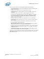
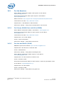
3.0 Getting Started
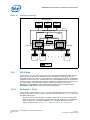
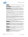
3.1 Installing the CMM
The Intel NetStructure
®
MPCMM0002 CMM is designed to fit in a variety of compatible
chassis and orientations. This chapter provides some useful information for installing
the management module in a chassis (shelf), but you will also need to read the third-
party documentation provided by the chassis manufacturer or system vendor for your
chassis before you install the module.
In addition to the information provided in the third-party documentation just
mentioned, you should also read and follow the precautions below:
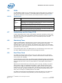
Caution: As noted in the PICMG* 3.0 specification, AdvancedTCA* products (including the
MPCMM0002 CMM) are designed to be installed and serviced by trained service
personnel only, not equipment operators. The primary reason for this is the high
voltage level (over 60 VDC) that can be present in AdvancedTCA systems.
Caution: Many components in the system contain sensitive electronic components. Service
personnel should follow proper grounding procedures when installing or servicing this
equipment.
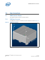
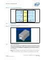
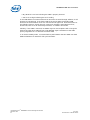
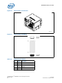
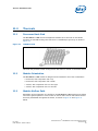
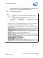
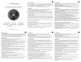
Figure 1. Top View of the Intel NetStructure
®
MPCMM0002 CMM

MPCMM0002 CMM—Getting Started
Intel NetStructure
®
MPCMM0002 Chassis Management Module
Hardware TPS July 2007
14 Order Number: 309247-004US
3.1.1 Quick Start
1. Open the packing material, find the packing list, and ensure that all the necessary
components are present for the Intel NetStructure
®
MPCMM0002 CMM.
2. Take the MPCMM0002 CMM to the chassis in which it will be installed.
3. Following standard ESD protection procedures, remove the CMM from its anti-static
bag.
4. Insert the management module into the card guides for the dedicated CMM slot.
Follow the chassis manufacturer’s or system vendor’s directions for the proper
orientation of the CMM.
5. As the CMM is being pushed into the slot, keep the ejector handle open until it
engages with the card guide. Ensure the alignment pins on the faceplate engage
the receptacles on the card cage. When the ejector handle engages, rotate the
ejector handle toward the faceplate until the card is fully seated.
6. Use a screwdriver or pair of pliers to tighten the retention screws on both ends of
the faceplate.
7. If the chassis power is on, the CMM will turn on automatically.
8. Connect the appropriate cables to the front or rear serial port, LAN ports. Connect
the telco alarm connector, if desired.
9. If a second CMM is to be installed in the chassis, follow the same instructions in this
procedure.
To remove the CMM:
1. Loosen the retention screws with a screw driver (Type#1 Philips head screw
driver).
2. Pull the ejector away from the faceplate (unlatch condition for ejector) enough to
ensure that the blue LED on the faceplate begins to flash. At this stage, the CMM
remains attached to the chassis (the backplane connector of CMM is still mated
with the chassis’s connector).
3. When the blue hot swap LED turns solid blue, pull the ejector farther out in order to
eject the CMM from the chassis.
Note: The hot swap LED will turn solid blue only when the redundancy feature is fully
enabled.

Intel NetStructure
®
MPCMM0002 Chassis Management Module
July 2007 Hardware TPS
Order Number: 309247-004US 15
Module Components—MPCMM0002 CMM
4.0 Module Components
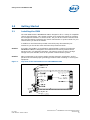
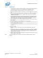
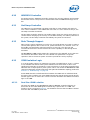
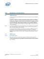
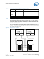
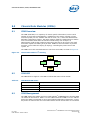
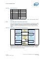
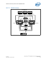
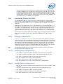
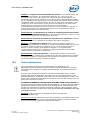
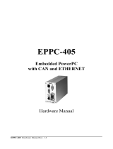
4.1 Block Diagram
The block diagram for the Intel NetStructure
®
MPCMM0002 CMM is shown in Figure 2.
Figure 2. CMM Block Diagram
80321
Intel®
XScale™
Core
and IOP
w/ PCI
Bridge
SODIMM
Socket
128MB
RJ45
SIO Serial
Controller
RS-232
Debug
CPLD
Latch
I
2
C
ADM1026
RTC
User
LEDs
Telco
Relays
Drivers
-48VDC Power
Control
Debug
Debug
LEDs
Battery
FRU
Clocks
OCS
10/100
NIC
Button
Alarm
BP
Switch
Mux
RTM
GPIO
8/16/32/64 MB
flash
10/100
NIC
Mux
RJ45
I
2
C
Control
Address
Decode
Interrupt
router
FPGA 2
GPIO
Engines
I
2
C
Control
Address
Decode
Interrupt
router
FPGA 1
GPIO
Engines
I
2
C[0:20]
I
2
C[21:41]
Alarm
LEDs
Health/
Fault
LED
3
4
Ejector
Blue LED
42 I
2
C

MPCMM0002 CMM—Module Components
Intel NetStructure
®
MPCMM0002 Chassis Management Module
Hardware TPS July 2007
16 Order Number: 309247-004US
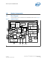
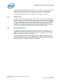
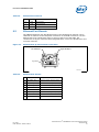
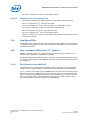
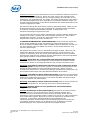
The major components of the CMM are arranged as shown in Figure 3.
The PCB is composed of 10 layers of FR406 (or equivalent material). The outer layers
(1 and 10) are 0.5 ounce copper (plated to 1.6 ounces); all other layers are 1 ounce
copper.
Note: S2 above is a four-pole DIP switch block. The first switch in the DIP, S2-1 (1:8), is used
for password reset; the other three switches, S2-2, S2-3, and S2-4, are currently not
used. The default position for S2-1 is the ‘off’ position (open). See the Intel
NetStructure
®
MPCMM0001 Chassis Management Module and Intel NetStructure
®
MPCMM0002 CMM Software Technical Product Specification for procedures on resetting
the CMM password.
Figure 3. CMM Top View Layout
B5106-01
Flash
FPGA
Battery
Super Cap
Power Brick
Bulk Cap
S2 switch
+ +
CPU
LED
Debug
LED
Relay RAM
Opto
NIC1
M
J3
NIC2
CPLD
LAN A
LAN B
Serial
Telco
Power
Guide
Pin
Data

Intel NetStructure
®
MPCMM0002 Chassis Management Module
July 2007 Hardware TPS
Order Number: 309247-004US 17
Module Components—MPCMM0002 CMM
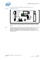
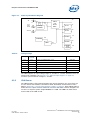
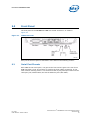
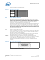
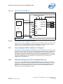
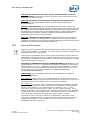
4.2 Intel
®
80321 Processor
The CPU in the MPCMM0002 CMM is an Intel
®
80321 Processor/PCI Application Bridge
with Intel
XScale
®
technology. The internal block diagram is shown in Figure 4.
This processor runs at 600 MHz and has an integrated chipset for lower power usage;
the typical power consumption of the CPU is 4 W. Other features are given in Table 2.
Figure 4. Intel
®
80321 Processor Internal Block Diagram
B3063-01
64-bit / 32-bit PCI Bus
DDR I/F
Unit
I
2
C
Serial Bus
Serial Bus
I
2
C Bus
Interface
Application
Accelerator
Performance
Monitoring
Unit
SSP
Serial Bus
Address
Translation
Unit
Intel
®
80321 I/O Processor
Two
DMA
Channels
Intel
®
XScale
®
Core
Internal Bus
PBI Unit
(Flash)
32-Bit
I/F
72-Bit
I/F
Messaging
Unit
Notes:
Intel
®
XScale
®
Microarchitecture is ARM* Architecture compliant.
* Other brands and names are the property of their respective owners.
Table 2. Processor Features (Sheet 1 of 2)
Integrated Intel XScale
®
Core
ARM* V5T Instruction Set
ARM V5E DSP Extensions
400 MHz and 600 MHz
Write Buffer, Write-back Cache

MPCMM0002 CMM—Module Components
Intel NetStructure
®
MPCMM0002 Chassis Management Module
Hardware TPS July 2007
18 Order Number: 309247-004US
PCI Bus Interface
PCI Local Bus Specification, Rev. 2.2 compliant
PCI-X Addendum to the PCI Local Bus Specification, Rev. 1.0a
64-bit/66 MHz Operation in PCI Mode
64-bit/133 MHz Operation in PCI-X Mode
Support 32-bit PCI Initiators and Targets
Four Split Read Requests as Initiator
Eight Split Read Requests as Target
64-bit Addressing Support
Memory Controller
PC200 Double Data Rate (DDR) SDRAM
Up to 1 GByte of 64-bit DDR SDRAM (128 MBytes on MPCMM0002)
Up to 512 MBytes of 32-bit DDR SDRAM
Single-bit Error Correction, Multi-bit Support (ECC)
1024 Byte Posted Memory Write Queue
40- and 72-bit wide Memory Interface
Address Translation Unit
2 KByte or 4 KByte Outbound Read Queue
4 KByte Outbound Write Queue
4 KByte Inbound Read and Write Queue
Connects Internal Bus to PCI/PCI-X Bus
DMA Controller
Two Independent Channels Connected to Internal Bus
Up to 1064 MByte/s Burst Support in PCI-X Mode
Up to 1600 MByte/s Burst Support for Internal Bus
Two 1 KB Queues in Ch-0 and Ch-1
232 Addressing Range on Internal Bus Interface
264 Addressing Range on PCI Interface
Application Accelerator Unit
Performs XOR on Read Data
Compute Parity Across Local Memory Blocks
1 KByte/512 Byte Store Queue
I
2
C Bus Interface Units
Two Separate I
2
C Units (one used on MPCMM0002)
Serial Bus
Master/Slave Capabilities
System Management Functions
SSP Serial Port
Full-duplex Synchronous Serial Interface
Supports 7.2 KHz to 1.84 MHz Bit Rates
Peripheral Performance
Monitoring Unit
One Dedicated Global Time Stamp Counter
Fourteen Programmable Event Counters
Three Control/Status Registers
Timers
Two Dual-programmable 32-bit Timers
Watchdog Timer
544-Ball, Plastic Ball Grid Array
(PBGA)
Eight General Purpose I/O Pins
Table 2. Processor Features (Sheet 2 of 2)

Intel NetStructure
®
MPCMM0002 Chassis Management Module
July 2007 Hardware TPS
Order Number: 309247-004US 19
Module Components—MPCMM0002 CMM
4.3 Memory
The CMM has a SODIMM (Small Outline Dual Inline Memory Module) socket on board.
The SODIMM is populated with a 128 MByte unbuffered memory module.
The CMM also has four separate 16 MByte flash modules. These are Intel
®
E28F128
flash memory modules. Each memory module has multiple lockable regions within the
flash.
4.4 Ethernet
The CMM has two Intel
®
82551QM Fast Ethernet Multifunction Controllers with
integrated media access controllers and physical interfaces. The output from each of
these chips is passed to a dedicated multiplexing device (mux), the SN74CBT16124.
Each mux can be individually controlled to send the Ethernet signals to one of three
destinations: the front panel, an optional RTM connection, or a separate backplane
connection. Separate magnetics (six total) provide magnetic coupling for the 10BASE-T
or 100BASE-TX signaling commonly associated with 10/100 MByte/s Ethernet.
In Figure 3, “CMM Top View Layout” on page 16, the four magnetics for the RTM and
backplane connections are at the bottom of the board. The two magnetics for the front
panel are integrated into the front panel RJ-45 connectors.
4.5 Serial Port UARTs
The UART (Universal Asynchronous Receiver/Transmitter) controller on the CMM board
is a Texas Instruments* TL16C752B dual UART chip. The first serial port is connected to
an RJ-45 connector on the front panel; the second serial port is passed to the rear of
the card for an optional RTM connection. Full modem hardware signals are passed
through to the RTM.
The UART driver provides 15 kV of ESD protection (8 kV contact, 15 kV air discharge).

MPCMM0002 CMM—Module Components
Intel NetStructure
®
MPCMM0002 Chassis Management Module
Hardware TPS July 2007
20 Order Number: 309247-004US
4.6 FPGA
The MPCMM0002 CMM has two redundant field-programmable gate arrays (FPGAs) on
board. These two Xilinx* Spartan* II XC2S200 FPGAs have identical internal design,
but different addresses. A brief summary of the FPGA functions is shown in Table 3.
4.7 Redundancy and Hot Swap CPLD
A Xilinx XC95144XL CPLD is used on the CMM to control the redundancy failover logic,
Hot Swap logic, FPGA control, and address decode for simple devices on the CMM. This
CPLD also contains the PCI arbitration circuitry for the 80321 processor and the
Ethernet controllers.
4.8 Watchdog Timer
A Maxim* MAX6374KA-T watchdog timer is used to protect against CPU lockups. The
CMM firmware strobes the watchdog periodically; if the CPU fails to strobe the
watchdog within a given time interval, the watchdog sends a signal to the CPLD that
forces the CPU to reset. This allows the processor to automatically recover to a known
good state in the case of lockup.
Note: If the watchdog timer fires, the IPMB signals are not affected by the CPU timer reset.
The other CMM automatically takes over and manages the chassis.
4.9 Real-Time Clock
The CMM time-stamps certain events as they occur within the system, particularly
entries into the System Event Log (SEL). A Dallas Semiconductor* DS1307 real-time
clock provides this capability.
To avoid losing the current time, the CMM provides independent power to the DS1307
with an on-board battery (size CR2032). The battery provides approximately five years
of run time for the clock in case of a power failure or if the CMM is removed from a
chassis.
Batteries have limited shelf lives. After many years in storage, a battery may not be
able to hold a charge. To supplement the battery, a super capacitor (SCap) is also
provided on the CMM; this provides a mechanism to get up to two hours of backup
power for the clock in case of a power failure. Though the SCap will not hold a charge
for even a full day, the ability to power the clock circuit during a power failure even
after years in storage is a reliability feature of the CMM.
The battery and SCap are both diode-OR’d to ensure that either one can supply the
power for the clock without being affected by the other backup power source.
Table 3. FPGA Features
Signal Description
IPMB
compatible
buses
IPMI 1.5-compliant buses, pulled up to 3.3 V and operating at 100 kHz
20 IPMB ports per FPGA (40 total): 32 IPMBs for dual star routing to up to 16
AdvancedTCA* slots, 2 shared buses for PEMs and fan trays, 2 buses for communication
between CMMs, and 4 spare IPMBs for future expansion
One I
2
C port per FPGA (2 total) for communication to CDMs
Bus 50nS basic memory bus with data, address, chip select, output enable, and write enable
Interrupt
Router
The FPGA is responsible for identifying and routing interrupt requests from multiple sources
on the CMM, including the following: internal IPMB engine, other FPGA, both UARTs, the
ADM1026 controller, the CPLD, and both LAN controllers

Intel NetStructure
®
MPCMM0002 Chassis Management Module
July 2007 Hardware TPS
Order Number: 309247-004US 21
Module Components—MPCMM0002 CMM
4.10 ADM1026 Controller
An Analog Devices* ADM1026 controller monitors the on-board voltages and manages
the thermal sensors. The processor communicates with the ADM1026 through an I
2
C
bus.
4.11 Hot Swap Controller
The CMM uses an LTC4250AH* Hot Swap controller to ramp voltages and watch for
over-current conditions. If the CMM draws more than 2.5 A for more than 500 µs, the
Hot Swap controller terminates.
The Hot Swap controller waits for the enable signals (short pins tied to each return) to
connect before ramping up the circuitry on the CMM. Similarly, if a CMM is pulled out of
the system, the Hot Swap controller immediately cuts power to the board.
4.12 Ride-Through Support
Many carriers require equipment to survive a 5 ms period without any power in order to
survive power glitches due to short circuit, power switchovers, etc. Section 4.1.4.3 of
the PICMG 3.0 specification requires boards to survive this 5 ms drop-out and
recommends that other chassis elements also have capability to ride through these
transients.
The MPCMM0002 CMM module meets this requirement. The CMM will survive the zero
volt transient described in Table 4-4 of the PICMG 3.0 specification. Large bulk
capacitors next to the DC-DC power converters provide this hold-up capacity.
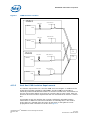
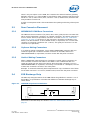
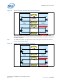
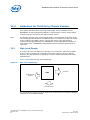
4.13 IPMB Isolation Logic
In a carrier-grade system it is important to prevent cascaded failures; that is, a failure
in one element that affects other system elements and causes them to fail or lose
significant functionality. A shared bus is more sensitive to a single item impacting other
elements than a simple point-to-point system. This is one reason the MPCMM0002 CMM
chassis management module implements the hybrid dual IPMB star topology outlined in
Section 6.1, “IPMB Routing” on page 28.
Some IPMB channels are dedicated links between the CMMs and an individual blade;
this type of link is called a star. Some IPMB channels are shared among several devices,
and this type of link is called a bus. The star and bus elements have different isolation
logic in the CMM.
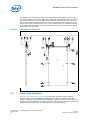
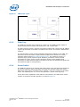
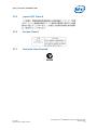
4.13.1 Dual Star IPMB Isolation
The dual star IPMBs on the MPCMM0002 CMM use MOSFET-controlled isolators to
disconnect all the radial IPMB signals automatically if power fails on a CMM. The
isolation circuit is pictured in Figure 5. The hardware ensures that the CMM is isolated
from the dual star IPMBs if power fails.
La pagina si sta caricando...
La pagina si sta caricando...
La pagina si sta caricando...
La pagina si sta caricando...
La pagina si sta caricando...
La pagina si sta caricando...
La pagina si sta caricando...
La pagina si sta caricando...
La pagina si sta caricando...
La pagina si sta caricando...
La pagina si sta caricando...
La pagina si sta caricando...
La pagina si sta caricando...
La pagina si sta caricando...
La pagina si sta caricando...
La pagina si sta caricando...
La pagina si sta caricando...
La pagina si sta caricando...
La pagina si sta caricando...
La pagina si sta caricando...
La pagina si sta caricando...
La pagina si sta caricando...
La pagina si sta caricando...
La pagina si sta caricando...
La pagina si sta caricando...
La pagina si sta caricando...
La pagina si sta caricando...
La pagina si sta caricando...
La pagina si sta caricando...
La pagina si sta caricando...
La pagina si sta caricando...
La pagina si sta caricando...
La pagina si sta caricando...
La pagina si sta caricando...
La pagina si sta caricando...
La pagina si sta caricando...
La pagina si sta caricando...
La pagina si sta caricando...
La pagina si sta caricando...
La pagina si sta caricando...
La pagina si sta caricando...
La pagina si sta caricando...
La pagina si sta caricando...
La pagina si sta caricando...
La pagina si sta caricando...
La pagina si sta caricando...
La pagina si sta caricando...
La pagina si sta caricando...
La pagina si sta caricando...
La pagina si sta caricando...
La pagina si sta caricando...
La pagina si sta caricando...
La pagina si sta caricando...
La pagina si sta caricando...
La pagina si sta caricando...
La pagina si sta caricando...
La pagina si sta caricando...
La pagina si sta caricando...
La pagina si sta caricando...
La pagina si sta caricando...
La pagina si sta caricando...
La pagina si sta caricando...
La pagina si sta caricando...
La pagina si sta caricando...
La pagina si sta caricando...
La pagina si sta caricando...
La pagina si sta caricando...
La pagina si sta caricando...
La pagina si sta caricando...
La pagina si sta caricando...
La pagina si sta caricando...
La pagina si sta caricando...
La pagina si sta caricando...
-
 1
1
-
 2
2
-
 3
3
-
 4
4
-
 5
5
-
 6
6
-
 7
7
-
 8
8
-
 9
9
-
 10
10
-
 11
11
-
 12
12
-
 13
13
-
 14
14
-
 15
15
-
 16
16
-
 17
17
-
 18
18
-
 19
19
-
 20
20
-
 21
21
-
 22
22
-
 23
23
-
 24
24
-
 25
25
-
 26
26
-
 27
27
-
 28
28
-
 29
29
-
 30
30
-
 31
31
-
 32
32
-
 33
33
-
 34
34
-
 35
35
-
 36
36
-
 37
37
-
 38
38
-
 39
39
-
 40
40
-
 41
41
-
 42
42
-
 43
43
-
 44
44
-
 45
45
-
 46
46
-
 47
47
-
 48
48
-
 49
49
-
 50
50
-
 51
51
-
 52
52
-
 53
53
-
 54
54
-
 55
55
-
 56
56
-
 57
57
-
 58
58
-
 59
59
-
 60
60
-
 61
61
-
 62
62
-
 63
63
-
 64
64
-
 65
65
-
 66
66
-
 67
67
-
 68
68
-
 69
69
-
 70
70
-
 71
71
-
 72
72
-
 73
73
-
 74
74
-
 75
75
-
 76
76
-
 77
77
-
 78
78
-
 79
79
-
 80
80
-
 81
81
-
 82
82
-
 83
83
-
 84
84
-
 85
85
-
 86
86
-
 87
87
-
 88
88
-
 89
89
-
 90
90
-
 91
91
-
 92
92
-
 93
93


Intel Drums MPCMM0002 Manuale utente
- Tipo
- Manuale utente
- Questo manuale è adatto anche per
in altre lingue
- English: Intel Drums MPCMM0002 User manual
Documenti correlati
Altri documenti
-
Xtorm FS401 Manuale utente
-
 MATRIX Labs MATRIX.C1.EU Manuale utente
-
 MATRIX Labs MATRIX.C1.US Manuale utente
-
Bosch Appliances Appliances Home Security System LTC 8540/00 Manuale utente
-
Xtorm XA082 Manuale utente
-
 ESD electronic I.2001.02 Manuale del proprietario
-
Nokia Solutions and Networks PHX-CPE25400 Manuale utente
-
EUROCOM D40EV IMPRESSA Manuale utente
-
Juniper Internet Router M160 Manuale utente
-


