
IBM
xSeries
450
Type
8688
Hardware
Maintenance
Manual
and
Troubleshooting
Guide
ERserver


IBM
xSeries
450
Type
8688
Hardware
Maintenance
Manual
and
Troubleshooting
Guide
ER s e r v e r

Note
Before
using
this
information
and
the
product
it
supports,
read
Appendix
C,
“Notices,”
on
page
237.
Fifth
Edition
(February
2004)
The
most
recent
version
of
this
document
is
available
on
the
World
Wide
Web
at
http://www.ibm.com/pc/support.
The
following
paragraph
does
not
apply
the
United
Kingdom
or
any
country
where
such
provisions
are
inconsistent
with
local
law:
INTERNATIONAL
BUSINESS
MACHINES
CORPORATION
PROVIDES
THIS
PUBLICATION
″AS
IS″
WITHOUT
WARRANTY
OF
ANY
KIND,
EITHER
EXPRESS
OR
IMPLIED,
INCLUDING,
BUT
NOT
LIMITED
TO,
THE
IMPLIED
WARRANTIES
OF
MERCHANTABILITY
OR
FITNESS
FOR
A
PARTICULAR
PURPOSE.
Some
states
do
not
allow
disclaimer
of
express
or
implied
warranties
in
certain
transactions,
therefore,
this
statement
may
not
apply
to
you.
This
information
could
include
technical
inaccuracies
or
typographical
errors.
Changes
are
periodically
made
to
the
information
herein;
these
changes
will
be
incorporated
in
new
editions
of
the
publication.
IBM
may
make
improvements
and/or
changes
in
the
product(s)
and/or
the
program(s)
described
in
this
publication
at
any
time.
This
publication
was
developed
for
products
and
services
offered
in
the
United
States
of
America.
IBM
may
not
offer
the
products,
services,
or
features
discussed
in
this
document
in
other
countries,
and
the
information
is
subject
to
change
without
notice.
Consult
your
local
IBM
representative
for
information
on
the
products,
services,
and
features
available
in
your
area.
Requests
for
technical
information
about
IBM
products
should
be
made
to
your
IBM
reseller
or
IBM
marketing
representative.
©
Copyright
International
Business
Machines
Corporation
2003.
All
rights
reserved.
US
Government
Users
Restricted
Rights
–
Use,
duplication
or
disclosure
restricted
by
GSA
ADP
Schedule
Contract
with
IBM
Corp.

About
this
manual
This
manual
contains
diagnostic
information,
a
Symptom-to-FRU
index,
service
information,
error
codes,
error
messages,
and
configuration
information
for
the
IBM
®
Eserver
™
xSeries
®
450
Type
8688
server.
Important:
The
field
replaceable
unit
(FRU)
procedures
are
intended
for
trained
servicers
who
are
familiar
with
IBM
products.
Before
servicing
an
IBM
product,
be
sure
to
review
“Safety
information”
on
page
197.
Important
safety
information
Be
sure
to
read
all
caution
and
danger
statements
in
this
book
before
performing
any
of
the
instructions.
See
“Safety
information”
on
page
197.
Leia
todas
as
instruções
de
cuidado
e
perigo
antes
de
executar
qualquer
operação.
Prenez
connaissance
de
toutes
les
consignes
de
type
Attention
et
Danger
avant
de
procéder
aux
opérations
décrites
par
les
instructions.
Lesen
Sie
alle
Sicherheitshinweise,
bevor
Sie
eine
Anweisung
ausführen.
Accertarsi
di
leggere
tutti
gli
avvisi
di
attenzione
e
di
pericolo
prima
di
effettuare
qualsiasi
operazione.
Lea
atentamente
todas
las
declaraciones
de
precaución
y
peligro
ante
de
llevar
a
cabo
cualquier
operación.
WARNING:
Handling
the
cord
on
this
product
or
cords
associated
with
accessories
sold
with
this
product
will
expose
you
to
lead,
a
chemical
known
to
the
State
of
California
to
cause
cancer,
and
birth
defects
or
other
reproductive
harm.
Wash
hands
after
handling.
ADVERTENCIA:
El
contacto
con
el
cable
de
este
producto
o
con
cables
de
accesorios
que
se
venden
junto
con
este
producto,
pueden
exponerle
al
plomo,
un
elemento
químico
que
en
el
estado
de
California
de
los
Estados
Unidos
está
considerado
como
un
causante
de
cancer
y
de
defectos
congénitos,
además
de
otros
riesgos
reproductivos.
Lávese
las
manos
después
de
usar
el
producto.
Online
support
You
can
download
the
most
current
diagnostic,
system
abstraction
layer/extensible
firmware
interface
(SAL/EFI)
flash,
and
device
driver
files
from
http://www.ibm.com/pc/support
on
the
World
Wide
Web.
©
Copyright
IBM
Corp.
2003
iii

iv
IBM
xSeries
450
Type
8688:
Hardware
Maintenance
Manual
and
Troubleshooting
Guide

Contents
About
this
manual
.
.
.
.
.
.
.
.
.
.
.
.
.
.
.
.
.
.
.
.
.
.
. iii
Important
safety
information
.
.
.
.
.
.
.
.
.
.
.
.
.
.
.
.
.
.
.
. iii
Online
support
.
.
.
.
.
.
.
.
.
.
.
.
.
.
.
.
.
.
.
.
.
.
.
.
. iii
Chapter
1.
General
information
.
.
.
.
.
.
.
.
.
.
.
.
.
.
.
.
.
.
.1
Related
publications
.
.
.
.
.
.
.
.
.
.
.
.
.
.
.
.
.
.
.
.
.
.
.1
Notices
and
statements
in
this
book
.
.
.
.
.
.
.
.
.
.
.
.
.
.
.
.
.2
Features
and
specifications
.
.
.
.
.
.
.
.
.
.
.
.
.
.
.
.
.
.
.
.
.3
What
your
IBM
xSeries
450
offers
.
.
.
.
.
.
.
.
.
.
.
.
.
.
.
.
.
.4
Server
controls
and
indicators
.
.
.
.
.
.
.
.
.
.
.
.
.
.
.
.
.
.
.
.4
Front
view
.
.
.
.
.
.
.
.
.
.
.
.
.
.
.
.
.
.
.
.
.
.
.
.
.
.5
Rear
view
.
.
.
.
.
.
.
.
.
.
.
.
.
.
.
.
.
.
.
.
.
.
.
.
.
.6
Server
power
features
.
.
.
.
.
.
.
.
.
.
.
.
.
.
.
.
.
.
.
.
.
.
.8
Turning
on
the
server
.
.
.
.
.
.
.
.
.
.
.
.
.
.
.
.
.
.
.
.
.
.8
Turning
off
the
server
.
.
.
.
.
.
.
.
.
.
.
.
.
.
.
.
.
.
.
.
.
.8
Chapter
2.
Configuring
the
server
.
.
.
.
.
.
.
.
.
.
.
.
.
.
.
.
.11
Using
the
Extensible
Firmware
Interface
(EFI)
Boot
Manager
.
.
.
.
.
.
.
.11
Using
the
Configuration/Setup
Utility
program
.
.
.
.
.
.
.
.
.
.
.
.
.12
Starting
the
Configuration/Setup
Utility
program
.
.
.
.
.
.
.
.
.
.
.
.12
Configuration/Setup
Utility
menu
choices
.
.
.
.
.
.
.
.
.
.
.
.
.
.12
Using
the
LSI
Logic
Configuration
Utility
program
.
.
.
.
.
.
.
.
.
.
.
.15
Setting
up
the
Remote
Supervisor
Adapter
.
.
.
.
.
.
.
.
.
.
.
.
.
.
.16
Remote
Supervisor
Adapter
features
.
.
.
.
.
.
.
.
.
.
.
.
.
.
.
.16
Setup
requirements
.
.
.
.
.
.
.
.
.
.
.
.
.
.
.
.
.
.
.
.
.
.16
Cabling
and
configuring
the
Remote
Supervisor
Adapter
.
.
.
.
.
.
.
.
.18
Using
the
ASM
interconnect
network
.
.
.
.
.
.
.
.
.
.
.
.
.
.
.
.26
Configuring
the
Gigabit
Ethernet
controller
.
.
.
.
.
.
.
.
.
.
.
.
.
.
.31
Chapter
3.
Diagnostics
.
.
.
.
.
.
.
.
.
.
.
.
.
.
.
.
.
.
.
.
.33
General
checkout
.
.
.
.
.
.
.
.
.
.
.
.
.
.
.
.
.
.
.
.
.
.
.
.33
Diagnostic
tools
overview
.
.
.
.
.
.
.
.
.
.
.
.
.
.
.
.
.
.
.
.
.35
POST
error
codes
and
messages
.
.
.
.
.
.
.
.
.
.
.
.
.
.
.
.
.
.35
System-error
logs
.
.
.
.
.
.
.
.
.
.
.
.
.
.
.
.
.
.
.
.
.
.
.
.36
Light
Path
Diagnostics
feature
.
.
.
.
.
.
.
.
.
.
.
.
.
.
.
.
.
.
.36
The
diagnostics
panel
.
.
.
.
.
.
.
.
.
.
.
.
.
.
.
.
.
.
.
.
.37
LEDs
on
the
top
of
the
server
.
.
.
.
.
.
.
.
.
.
.
.
.
.
.
.
.
.37
LEDs
on
the
system
boards
.
.
.
.
.
.
.
.
.
.
.
.
.
.
.
.
.
.
.37
Diagnostic
display
.
.
.
.
.
.
.
.
.
.
.
.
.
.
.
.
.
.
.
.
.
.
.
.37
Diagnostic
programs,
error
codes,
and
messages
.
.
.
.
.
.
.
.
.
.
.
.38
Text
messages
.
.
.
.
.
.
.
.
.
.
.
.
.
.
.
.
.
.
.
.
.
.
.
.38
Starting
the
AMIDiag
program
.
.
.
.
.
.
.
.
.
.
.
.
.
.
.
.
.
.38
AMIDiag
menus
.
.
.
.
.
.
.
.
.
.
.
.
.
.
.
.
.
.
.
.
.
.
.40
System
diagnostic
tests
.
.
.
.
.
.
.
.
.
.
.
.
.
.
.
.
.
.
.
.
.42
Memory
diagnostic
tests
.
.
.
.
.
.
.
.
.
.
.
.
.
.
.
.
.
.
.
.44
IDE
device
diagnostic
tests
.
.
.
.
.
.
.
.
.
.
.
.
.
.
.
.
.
.
.44
SCSI
diagnostic
tests
.
.
.
.
.
.
.
.
.
.
.
.
.
.
.
.
.
.
.
.
.46
Video
diagnostic
tests
.
.
.
.
.
.
.
.
.
.
.
.
.
.
.
.
.
.
.
.
.51
USB
diagnostic
tests
.
.
.
.
.
.
.
.
.
.
.
.
.
.
.
.
.
.
.
.
.
.53
Miscellaneous
diagnostic
tests
.
.
.
.
.
.
.
.
.
.
.
.
.
.
.
.
.
.60
Options
menu
.
.
.
.
.
.
.
.
.
.
.
.
.
.
.
.
.
.
.
.
.
.
.
.63
Ethernet
diagnostic
tests
.
.
.
.
.
.
.
.
.
.
.
.
.
.
.
.
.
.
.
.70
Diagnostic
error
code
tables
.
.
.
.
.
.
.
.
.
.
.
.
.
.
.
.
.
.
.70
©
Copyright
IBM
Corp.
2003
v

Small
computer
system
interface
(SCSI)
messages
.
.
.
.
.
.
.
.
.
.
.71
Recovering
SAL/EFI
code
.
.
.
.
.
.
.
.
.
.
.
.
.
.
.
.
.
.
.
.
.71
Clearing
a
power-on
password
.
.
.
.
.
.
.
.
.
.
.
.
.
.
.
.
.
.
.72
Clearing
CMOS
.
.
.
.
.
.
.
.
.
.
.
.
.
.
.
.
.
.
.
.
.
.
.
.
.73
Power
checkout
.
.
.
.
.
.
.
.
.
.
.
.
.
.
.
.
.
.
.
.
.
.
.
.74
Troubleshooting
the
Ethernet
controller
.
.
.
.
.
.
.
.
.
.
.
.
.
.
.
.75
Network
connection
problems
.
.
.
.
.
.
.
.
.
.
.
.
.
.
.
.
.
.75
Ethernet
controller
troubleshooting
chart
.
.
.
.
.
.
.
.
.
.
.
.
.
.76
Ethernet
controller
messages
.
.
.
.
.
.
.
.
.
.
.
.
.
.
.
.
.
.76
Chapter
4.
Installing
options
.
.
.
.
.
.
.
.
.
.
.
.
.
.
.
.
.
.
.77
Installation
guidelines
.
.
.
.
.
.
.
.
.
.
.
.
.
.
.
.
.
.
.
.
.
.77
System
reliability
considerations
.
.
.
.
.
.
.
.
.
.
.
.
.
.
.
.
.77
Working
inside
a
server
with
power
on
.
.
.
.
.
.
.
.
.
.
.
.
.
.
.77
Handling
static-sensitive
devices
.
.
.
.
.
.
.
.
.
.
.
.
.
.
.
.
.78
Major
components
of
the
xSeries
450
server
.
.
.
.
.
.
.
.
.
.
.
.
.
.78
Connector
and
LED
locations
.
.
.
.
.
.
.
.
.
.
.
.
.
.
.
.
.
.
.80
Memory
board
internal
connectors
and
LEDs
.
.
.
.
.
.
.
.
.
.
.
.
.80
Memory
switch
card
LEDs
.
.
.
.
.
.
.
.
.
.
.
.
.
.
.
.
.
.
.
.81
Processor
board
internal
connectors
and
LEDs
.
.
.
.
.
.
.
.
.
.
.
.82
Midplane
board
connectors
and
LEDs
.
.
.
.
.
.
.
.
.
.
.
.
.
.
.84
PCI-X
board
internal
connectors
and
LEDs
.
.
.
.
.
.
.
.
.
.
.
.
.86
I/O-board
internal
connectors
.
.
.
.
.
.
.
.
.
.
.
.
.
.
.
.
.
.
.87
I/O-board
jumpers
.
.
.
.
.
.
.
.
.
.
.
.
.
.
.
.
.
.
.
.
.
.
.87
Remote
Supervisor
Adapter
connectors
and
LEDs
.
.
.
.
.
.
.
.
.
.
.88
Opening
the
cover
.
.
.
.
.
.
.
.
.
.
.
.
.
.
.
.
.
.
.
.
.
.
.88
Removing
and
replacing
the
bezel
.
.
.
.
.
.
.
.
.
.
.
.
.
.
.
.
.
.89
Removing
and
replacing
a
hot-swap
power
supply
.
.
.
.
.
.
.
.
.
.
.
.90
Installing
an
adapter
.
.
.
.
.
.
.
.
.
.
.
.
.
.
.
.
.
.
.
.
.
.
.92
Installing
a
hot-swap
hard
disk
drive
.
.
.
.
.
.
.
.
.
.
.
.
.
.
.
.
.95
Installing
a
1.44
MB
diskette
drive
.
.
.
.
.
.
.
.
.
.
.
.
.
.
.
.
.
.96
Installing
a
CD-ROM
or
DVD-ROM
drive
.
.
.
.
.
.
.
.
.
.
.
.
.
.
.97
Installing
memory
.
.
.
.
.
.
.
.
.
.
.
.
.
.
.
.
.
.
.
.
.
.
.
.98
Installing
and
replacing
a
microprocessor
and
power
module
.
.
.
.
.
.
. 100
Replacing
and
troubleshooting
fans
.
.
.
.
.
.
.
.
.
.
.
.
.
.
.
.
. 107
Replacing
fan
1
or
2
.
.
.
.
.
.
.
.
.
.
.
.
.
.
.
.
.
.
.
.
. 107
Replacing
fan
3
or
4
.
.
.
.
.
.
.
.
.
.
.
.
.
.
.
.
.
.
.
.
. 108
Replacing
the
battery
.
.
.
.
.
.
.
.
.
.
.
.
.
.
.
.
.
.
.
.
.
. 109
Completing
the
installation
.
.
.
.
.
.
.
.
.
.
.
.
.
.
.
.
.
.
.
. 111
Closing
the
cover
.
.
.
.
.
.
.
.
.
.
.
.
.
.
.
.
.
.
.
.
.
.
. 111
Connecting
the
cables
.
.
.
.
.
.
.
.
.
.
.
.
.
.
.
.
.
.
.
.
. 111
Updating
your
server
configuration
.
.
.
.
.
.
.
.
.
.
.
.
.
.
.
.112
Installing
the
server
in
a
rack
.
.
.
.
.
.
.
.
.
.
.
.
.
.
.
.
.
.113
Chapter
5.
Field
replaceable
units
.
.
.
.
.
.
.
.
.
.
.
.
.
.
.
.
.115
Memory-board
assembly
.
.
.
.
.
.
.
.
.
.
.
.
.
.
.
.
.
.
.
.
.115
Memory
board
.
.
.
.
.
.
.
.
.
.
.
.
.
.
.
.
.
.
.
.
.
.
.
.115
Memory-board
voltage
regulator
module
(VRM)
.
.
.
.
.
.
.
.
.
.
.116
Memory
switch
card
and
cable
.
.
.
.
.
.
.
.
.
.
.
.
.
.
.
.
.
.118
Processor-board
assembly
.
.
.
.
.
.
.
.
.
.
.
.
.
.
.
.
.
.
.
.119
Microprocessor
and
power
module
.
.
.
.
.
.
.
.
.
.
.
.
.
.
.
. 121
Processor-board
VRM
.
.
.
.
.
.
.
.
.
.
.
.
.
.
.
.
.
.
.
.
. 122
PCI-X
board
assembly
.
.
.
.
.
.
.
.
.
.
.
.
.
.
.
.
.
.
.
.
. 123
Midplane
board
.
.
.
.
.
.
.
.
.
.
.
.
.
.
.
.
.
.
.
.
.
.
. 125
Midplane-board
VRM
.
.
.
.
.
.
.
.
.
.
.
.
.
.
.
.
.
.
.
.
. 126
PCI-X
board
.
.
.
.
.
.
.
.
.
.
.
.
.
.
.
.
.
.
.
.
.
.
.
. 127
vi
IBM
xSeries
450
Type
8688:
Hardware
Maintenance
Manual
and
Troubleshooting
Guide

Active
PCI
assembly
.
.
.
.
.
.
.
.
.
.
.
.
.
.
.
.
.
.
.
.
. 129
I/O
board,
riser
card,
and
Remote
Supervisor
Adapter
.
.
.
.
.
.
.
.
. 130
Restoring
the
nonvolatile
EFI
variables
.
.
.
.
.
.
.
.
.
.
.
.
.
. 134
Top
cover
assembly
.
.
.
.
.
.
.
.
.
.
.
.
.
.
.
.
.
.
.
.
.
. 137
Top
power
board
.
.
.
.
.
.
.
.
.
.
.
.
.
.
.
.
.
.
.
.
.
.
.
. 138
Hard
disk
drive
backplane
.
.
.
.
.
.
.
.
.
.
.
.
.
.
.
.
.
.
.
. 138
Media
bay
card
.
.
.
.
.
.
.
.
.
.
.
.
.
.
.
.
.
.
.
.
.
.
.
. 139
Memory-board
retaining
latches
.
.
.
.
.
.
.
.
.
.
.
.
.
.
.
.
.
. 140
AC
box
assembly
mechanism
.
.
.
.
.
.
.
.
.
.
.
.
.
.
.
.
.
.
. 141
Media-extract
mechanism
.
.
.
.
.
.
.
.
.
.
.
.
.
.
.
.
.
.
.
. 143
Power/reset
card
assembly
.
.
.
.
.
.
.
.
.
.
.
.
.
.
.
.
.
.
.
. 144
Light
Path
card
.
.
.
.
.
.
.
.
.
.
.
.
.
.
.
.
.
.
.
.
.
.
.
. 144
Chapter
6.
Symptom-to-FRU
index
.
.
.
.
.
.
.
.
.
.
.
.
.
.
.
. 147
Light
Path
LED
errors
.
.
.
.
.
.
.
.
.
.
.
.
.
.
.
.
.
.
.
.
.
. 147
System-error
log
entries
.
.
.
.
.
.
.
.
.
.
.
.
.
.
.
.
.
.
.
.
. 149
SAL/EFI
messages
.
.
.
.
.
.
.
.
.
.
.
.
.
.
.
.
.
.
.
.
.
. 150
Service
processor
messages
.
.
.
.
.
.
.
.
.
.
.
.
.
.
.
.
.
. 154
Diagnostic
error
codes
.
.
.
.
.
.
.
.
.
.
.
.
.
.
.
.
.
.
.
.
. 159
System-error
codes
.
.
.
.
.
.
.
.
.
.
.
.
.
.
.
.
.
.
.
.
.
. 159
IDE
CD
test
error
codes
.
.
.
.
.
.
.
.
.
.
.
.
.
.
.
.
.
.
.
. 161
ATAPI
removables
test
error
codes
.
.
.
.
.
.
.
.
.
.
.
.
.
.
.
. 162
IDE
DVD-ROM
drive
test
error
codes
.
.
.
.
.
.
.
.
.
.
.
.
.
.
. 164
SCSI
test
error
codes
.
.
.
.
.
.
.
.
.
.
.
.
.
.
.
.
.
.
.
.
. 164
Video
test
error
codes
.
.
.
.
.
.
.
.
.
.
.
.
.
.
.
.
.
.
.
.
. 167
USB
test
error
codes
.
.
.
.
.
.
.
.
.
.
.
.
.
.
.
.
.
.
.
.
. 167
Serial
port
test
error
codes
.
.
.
.
.
.
.
.
.
.
.
.
.
.
.
.
.
.
. 169
Advanced
System
Management
error
codes
.
.
.
.
.
.
.
.
.
.
.
. 170
RXE
port
error
codes
.
.
.
.
.
.
.
.
.
.
.
.
.
.
.
.
.
.
.
.
. 173
Memory
test
error
codes
.
.
.
.
.
.
.
.
.
.
.
.
.
.
.
.
.
.
.
. 174
LED
error
codes
.
.
.
.
.
.
.
.
.
.
.
.
.
.
.
.
.
.
.
.
.
.
. 175
Error
symptoms
.
.
.
.
.
.
.
.
.
.
.
.
.
.
.
.
.
.
.
.
.
.
.
. 176
Power
supply
LED
errors
.
.
.
.
.
.
.
.
.
.
.
.
.
.
.
.
.
.
.
.
. 180
Diagnostic
display
error
codes
.
.
.
.
.
.
.
.
.
.
.
.
.
.
.
.
.
.
. 181
Hardware
status
error
codes
.
.
.
.
.
.
.
.
.
.
.
.
.
.
.
.
.
. 181
SAL/EFI
progress
codes
.
.
.
.
.
.
.
.
.
.
.
.
.
.
.
.
.
.
.
. 183
SCSI
error
messages
.
.
.
.
.
.
.
.
.
.
.
.
.
.
.
.
.
.
.
.
.
. 184
Ethernet
error
messages
.
.
.
.
.
.
.
.
.
.
.
.
.
.
.
.
.
.
.
.
. 185
Undetermined
problems
.
.
.
.
.
.
.
.
.
.
.
.
.
.
.
.
.
.
.
.
. 185
Chapter
7.
Parts
listing
xSeries
450
Type
8688
.
.
.
.
.
.
.
.
.
.
.
. 187
System
.
.
.
.
.
.
.
.
.
.
.
.
.
.
.
.
.
.
.
.
.
.
.
.
.
.
. 187
Figure
A
.
.
.
.
.
.
.
.
.
.
.
.
.
.
.
.
.
.
.
.
.
.
.
.
.
.
. 190
Figure
B
.
.
.
.
.
.
.
.
.
.
.
.
.
.
.
.
.
.
.
.
.
.
.
.
.
.
. 191
Keyboard
CRUs
.
.
.
.
.
.
.
.
.
.
.
.
.
.
.
.
.
.
.
.
.
.
.
. 192
Power
cord
CRUs
.
.
.
.
.
.
.
.
.
.
.
.
.
.
.
.
.
.
.
.
.
.
. 193
Appendix
A.
Getting
help
and
technical
assistance
.
.
.
.
.
.
.
.
.
. 195
Before
you
call
.
.
.
.
.
.
.
.
.
.
.
.
.
.
.
.
.
.
.
.
.
.
.
. 195
Using
the
documentation
.
.
.
.
.
.
.
.
.
.
.
.
.
.
.
.
.
.
.
.
. 195
Getting
help
and
information
from
the
World
Wide
Web
.
.
.
.
.
.
.
.
. 195
Software
service
and
support
.
.
.
.
.
.
.
.
.
.
.
.
.
.
.
.
.
.
. 196
Hardware
service
and
support
.
.
.
.
.
.
.
.
.
.
.
.
.
.
.
.
.
.
. 196
Appendix
B.
Related
service
information
.
.
.
.
.
.
.
.
.
.
.
.
.
. 197
Safety
information
.
.
.
.
.
.
.
.
.
.
.
.
.
.
.
.
.
.
.
.
.
.
. 197
Contents
vii

General
safety
.
.
.
.
.
.
.
.
.
.
.
.
.
.
.
.
.
.
.
.
.
.
. 197
Electrical
safety
.
.
.
.
.
.
.
.
.
.
.
.
.
.
.
.
.
.
.
.
.
.
. 198
Safety
inspection
guide
.
.
.
.
.
.
.
.
.
.
.
.
.
.
.
.
.
.
.
. 199
Handling
static-sensitive
devices
.
.
.
.
.
.
.
.
.
.
.
.
.
.
.
.
. 200
Grounding
requirements
.
.
.
.
.
.
.
.
.
.
.
.
.
.
.
.
.
.
.
. 200
Safety
notices
(multilingual
translations)
.
.
.
.
.
.
.
.
.
.
.
.
.
. 201
Appendix
C.
Notices
.
.
.
.
.
.
.
.
.
.
.
.
.
.
.
.
.
.
.
.
.
. 237
Edition
notice
.
.
.
.
.
.
.
.
.
.
.
.
.
.
.
.
.
.
.
.
.
.
.
.
. 237
Trademarks
.
.
.
.
.
.
.
.
.
.
.
.
.
.
.
.
.
.
.
.
.
.
.
.
.
. 238
Important
notes
.
.
.
.
.
.
.
.
.
.
.
.
.
.
.
.
.
.
.
.
.
.
.
. 238
Product
recycling
and
disposal
.
.
.
.
.
.
.
.
.
.
.
.
.
.
.
.
.
. 239
Battery
return
program
.
.
.
.
.
.
.
.
.
.
.
.
.
.
.
.
.
.
.
.
. 239
Electronic
emission
notices
.
.
.
.
.
.
.
.
.
.
.
.
.
.
.
.
.
.
.
. 240
Federal
Communications
Commission
(FCC)
statement
.
.
.
.
.
.
.
. 240
Industry
Canada
Class
A
emission
compliance
statement
.
.
.
.
.
.
.
. 240
Australia
and
New
Zealand
Class
A
statement
.
.
.
.
.
.
.
.
.
.
.
. 240
United
Kingdom
telecommunications
safety
requirement
.
.
.
.
.
.
.
. 240
European
Union
EMC
Directive
conformance
statement
.
.
.
.
.
.
.
. 240
Taiwanese
Class
A
warning
statement
.
.
.
.
.
.
.
.
.
.
.
.
.
.
. 241
Chinese
Class
A
warning
statement
.
.
.
.
.
.
.
.
.
.
.
.
.
.
.
. 241
Japanese
Voluntary
Control
Council
for
Interference
(VCCI)
statement
241
Power
cords
.
.
.
.
.
.
.
.
.
.
.
.
.
.
.
.
.
.
.
.
.
.
.
.
. 241
Index
.
.
.
.
.
.
.
.
.
.
.
.
.
.
.
.
.
.
.
.
.
.
.
.
.
.
.
. 245
viii
IBM
xSeries
450
Type
8688:
Hardware
Maintenance
Manual
and
Troubleshooting
Guide

Chapter
1.
General
information
Your
IBM
Eserver
xSeries
450
Type
8688
server
is
a
high-performance
symmetric
multiprocessing
(SMP)
server.
It
is
ideally
suited
for
networking
environments
that
require
superior
microprocessor
performance,
efficient
memory
management,
flexibility,
and
reliable
data
storage.
The
xSeries
450
server
contains
several
IBM
X-Architecture
™
technologies,
which
help
increase
server
performance
and
reliability.
Your
server
comes
with
a
limited
warranty.
If
you
have
access
to
the
World
Wide
Web,
you
can
obtain
up-to-date
information
about
your
server
model
and
other
IBM
server
products
at
http://www.ibm.com/pc/us/eserver/xseries/.
Your
server
serial
number
and
model
number
are
on
the
ID
label
located
on
the
left
side
of
the
bezel
just
above
the
hard
disk
drives.
You
will
need
these
numbers
when
you
register
your
server
with
IBM.
The
information
label
containing
the
serial
number,
machine
type,
model
number,
and
agency
marks
for
your
server
is
on
the
bottom
of
the
server.
Related
publications
This
Hardware
Maintenance
Manual
and
Troubleshooting
Guide
contains
information
to
help
you
solve
the
problem
yourself
or
to
provide
helpful
information
to
a
service
technician.
In
addition
to
this
Hardware
Maintenance
Manual
and
Troubleshooting
Guide,
the
following
xSeries
450
Type
8688
documentation
is
provided
with
your
server:
v
Installation
Guide
This
printed
publication
contains
setup
and
installation
instructions.
v
Rack
Installation
Instructions
This
printed
publication
contains
the
instructions
to
install
your
server
in
a
rack.
v
Safety
Book
This
multilingual
publication
is
provided
in
Portable
Document
Format
(PDF)
on
the
IBM
xSeries
Documentation
CD.
It
contains
translated
versions
of
the
caution
and
danger
statements
that
appear
in
the
documentation
for
your
server.
Each
caution
and
danger
statement
has
an
assigned
number,
which
you
can
use
to
locate
the
corresponding
statement
in
your
native
language.
v
User’s
Guide
This
publication
is
provided
in
PDF
on
the
IBM
xSeries
Documentation
CD.
It
contains
general
information
about
your
server,
including
information
about
features,
how
to
configure
your
server,
and
how
to
get
help.
v
Option
Installation
Guide
This
publication
is
provided
in
PDF
on
the
IBM
xSeries
Documentation
CD.
It
contains
instructions
to
install,
remove,
and
connect
optional
devices
supported
by
your
server.
Depending
on
your
server
model,
additional
publications
might
be
included
on
the
IBM
xSeries
Documentation
CD.
©
Copyright
IBM
Corp.
2003
1

Notices
and
statements
in
this
book
The
caution
and
danger
statements
used
in
this
book
also
appear
in
the
multilingual
Safety
Information
book
provided
on
the
IBM
xSeries
Documentation
CD.
Each
caution
and
danger
statement
is
numbered
for
easy
reference
to
the
corresponding
statements
in
the
safety
book.
The
following
types
of
notices
and
statements
are
used
in
this
book:
v
Note:
These
notices
provide
important
tips,
guidance,
or
advice.
v
Important:
These
notices
provide
information
or
advice
that
might
help
you
avoid
inconvenient
or
problem
situations.
v
Attention:
These
notices
indicate
possible
damage
to
programs,
devices,
or
data.
An
attention
notice
is
placed
just
before
the
instruction
or
situation
in
which
damage
could
occur.
v
Caution:
These
statements
indicate
situations
that
can
be
potentially
hazardous
to
you.
A
caution
statement
is
placed
just
before
the
description
of
a
potentially
hazardous
procedure
step
or
situation.
v
Danger:
These
statements
indicate
situations
that
can
be
potentially
lethal
or
extremely
hazardous
to
you.
A
danger
statement
is
placed
just
before
the
description
of
a
potentially
lethal
or
extremely
hazardous
procedure
step
or
situation.
2
IBM
xSeries
450
Type
8688:
Hardware
Maintenance
Manual
and
Troubleshooting
Guide

Features
and
specifications
The
following
table
provides
a
summary
of
the
features
and
specifications
of
your
xSeries
450.
Microprocessor:
v
Intel
®™
Itanium
®
2
900
MHz
or
higher,
depending
on
server
model
v
1.5
MB
(minimum)
Level-3
cache
v
200
MHz
front-side
bus
(FSB),
at
two
data
transfers
per
cycle,
yielding
a
400
MHz
system
bus
(minimum)
v
Support
for
up
to
four
microprocessors
v
XceL4
™
Server
Accelerator
Cache:
64
MB
Active
Memory
™
:
v
Minimum:
1
GB
v
Maximum:
40
GB
v
Type:
2-way
interleaved
PC2100,
ECC
DDR
SDRAM,
registered
DIMMs
only
v
Supports
512
MB,
1
GB,
and
2
GB
dual
inline
memory
modules
(DIMMs)
Drives
standard:
DVD/CD-RW:
IDE
Expansion
bays:
v
Two
removable
media
bays
(one
DVD/CD-RW
preinstalled)
v
Supports
up
to
two
internal
Ultra320
SCSI
hard
disk
drives
Active
™
PCI-X
expansion
slots:
Six
64-bit
Active
PCI-X
expansion
slots:
v
Two
66
MHz
PCI-X
slots
v
Two
100
MHZ
PCI-X
slots
v
Two
133
MHZ
PCI-X
slots
Cooling:
Four
hot-swap
fans
v
Two
150
mm
x
51
mm
fans
v
Two
150
mm
x
38
mm
fans
Acoustical
noise
emissions:
v
Declared
sound
power,
idle:
6.5
bels
v
Declared
sound
power,
operating:
6.5
bels
v
Bystander
sound
pressure,
idle:
49
dBa
v
Bystander
sound
pressure,
operating:
49
dBa
Power
supply:
Two
power
supplies:
550
watts
at
100-127
V
ac
or
1050
watts
at
200-240
V
ac
(hot-swappable
and
redundant
at
200-240
V
ac
only)
Video:
v
Integrated
ATI
RageXL
video
v
PCI
bus
interface
v
Compatible
with
SVGA
v
8
MB
SDRAM
video
memory
Size
(4
U):
v
Height:
17.8
cm
(7
inches,
4
U)
v
Depth:
69.85
cm
(27.5
inches)
v
Width:
48.3
cm
(19
inches)
v
Maximum
weight:
38.6
kg
(85
lb),
depending
on
your
configuration
Integrated
functions:
v
Broadcom
5704
10/100/1000
dual
port
Ethernet
controller
v
Light
Path
Diagnostics
™
v
One
external
and
one
internal
Ultra320
SCSI
port
(dual-channel
integrated
controller
with
RAID
capabilities)
v
Remote
Supervisor
Adapter
(service
processor)
–
ASM
interconnect
(peer-to-peer)
port
–
Ethernet
port
–
Serial
port
v
IDE
controller
v
RXE
Management
port
v
RXE
Expansion
ports
v
Three
USB
ports
v
SCSI
ports
v
Serial
port
v
Wake
on
LAN
®
Environment:
v
Air
temperature:
–
Server
on:
10°
to
35°C
(50.0°
to
95.0°F).
Altitude:
0
to
914
m
(2998.7
ft)
–
Server
on:
10°
to
32°C
(50.0°
to
89.6°F).
Altitude:
0
to
2133
m
(6998.0
ft)
–
Server
off:
-40°
to
60°C
(-104°
to
140°F).
Maximum
altitude:
2133
m
(6998.0
ft)
v
Humidity:
–
Server
on:
8%
to
80%
–
Server
off:
5%
to
100%
Heat
output:
Approximate
heat
output
in
British
thermal
units
(Btu)
per
hour
v
Minimum
configuration:
854
Btu
(250
watts)
v
Maximum
configuration:
2646
Btu
(775
watts)
Electrical
input:
v
Sine-wave
input
(50-60
Hz)
required
v
Input
voltage
low
range:
–
Minimum:
100
V
ac
–
Maximum:
127
V
ac
v
Input
voltage
high
range:
–
Minimum:
200
V
ac
–
Maximum:
240
V
ac
v
Input
kilovolt-amperes
(kVA)
approximately:
–
Minimum:
0.250
kVA
–
Maximum:
1.3
kVA
Notes:
1.
Power
consumption
and
heat
output
vary
depending
on
the
number
and
type
of
optional
features
installed
and
the
power-management
optional
features
in
use.
2.
These
levels
were
measured
in
controlled
acoustical
environments
according
to
the
procedures
specified
by
the
American
National
Standards
Institute
(ANSI)
S12.10
and
ISO
7779
and
are
reported
in
accordance
with
ISO
9296.
Actual
sound-pressure
levels
in
a
given
location
might
exceed
the
average
values
stated
because
of
room
reflections
and
other
nearby
noise
sources.
The
declared
sound-power
levels
indicate
an
upper
limit,
below
which
a
large
number
of
computers
will
operate.
Chapter
1.
General
information
3

What
your
IBM
xSeries
450
offers
Your
server
includes
the
following
features
and
technologies:
v
IBM
Enterprise
X-Architecture
technology
Enterprise
X-Architecture
technology
combines
proven,
innovative
IBM
designs
to
make
your
Intel-processor-based
server
powerful,
scalable,
and
reliable.
For
more
information,
go
to
http://www.ibm.com/pc/us/eserver/xseries/xarchitecture/enterprise/index.html
on
the
World
Wide
Web.
–
Active
Memory
The
Active
Memory
feature
improves
the
reliability
of
memory
through
memory
mirroring,
memory
scrubbing,
and
the
Memory
ProteXion
™
feature.
For
more
information,
see
the
User’s
Guide.
–
Large
system
memory
The
memory
bus
supports
up
to
40
GB
of
system
memory.
The
memory
controller
provides
error
code
correcting
(ECC)
support
for
up
to
28
industry-standard
PC2100,
2.5
V,
184-pin,
133
megahertz
(MHz),
registered,
double
data
rate
(DDR),
synchronous
dynamic
random
access
memory
(SDRAM)
dual
inline
memory
modules
(DIMMs).
–
XceL4
™
Server
Accelerator
Cache
The
XceL4
Server
Accelerator
Cache
provides
64
MB
of
external
Level-4
cache,
which
increases
effective
memory
bandwidth.
v
Light
Path
Diagnostics
feature
The
Light
Path
Diagnostics
feature
provides
LEDs
to
help
you
isolate
problems.
For
more
information,
see
“Light
Path
Diagnostics
feature”
on
page
36.
v
System-management
capabilities
The
server
comes
with
a
Remote
Supervisor
Adapter
installed
in
a
dedicated
connector.
This
adapter,
in
conjunction
with
the
system-management
software
that
comes
with
the
server,
enables
you
to
manage
the
functions
of
the
server
locally
and
remotely.
The
Remote
Supervisor
Adapter
also
provides
system
monitoring,
event
recording,
and
dial-out
alert
capability.
v
Integrated
network
support
Your
server
comes
with
an
integrated
Broadcom
Gigabit
Ethernet
controller,
which
supports
connection
to
a
10-Mbps,
100-Mbps,
or
1000-Mbps
network.
For
more
information,
see
“Configuring
the
Gigabit
Ethernet
controller”
on
page
31.
Server
controls
and
indicators
The
following
section
identifies
the
controls
and
indicators
on
the
front
and
rear
of
your
server.
Note:
Illustrations
in
this
document
might
differ
slightly
from
your
hardware.
4
IBM
xSeries
450
Type
8688:
Hardware
Maintenance
Manual
and
Troubleshooting
Guide

Front
view
Power button
Reset button
Power-on LED
Hard disk drive activity LED (green)
Hard disk drive error LED (amber)
USB
connector
System-error LED
(amber)
Information LED
(amber)
SCSI activity LED
(green)
Locator LED
(blue)
Drive eject button
DVD/CD-RW
eject button
DVD/CD-RW
drive activity LED
Power-supply
latch
Drive
eject button
Power-on
LED:
This
green
LED
turns
on
and
stays
on
when
you
turn
on
your
server,
and
it
flashes
when
the
server
is
in
Standby
mode.
Hard
disk
drive
activity
LED:
When
this
green
LED
is
lit,
it
indicates
that
the
hard
disk
drive
is
in
use.
Hard
disk
drive
error
LED:
On
some
server
models,
each
hot-swap
hard
disk
drive
has
an
error
LED.
The
interpretation
of
a
flashing
error
LED
depends
on
the
SCSI
controller
connected
to
the
hot-swap
drive.
When
the
drive
is
connected
to
the
integrated
SCSI
controller
with
RAID
capabilities,
a
flashing
error
LED
indicates
that
the
drive
is
a
secondary
drive
in
a
mirrored
pair
and
the
drive
is
being
synchronized.
USB
connector:
This
is
an
automatically
configured
port
that
you
can
use
to
connect
one
or
more
USB
devices
to
the
front
of
the
server,
using
Plug
and
Play
technology.
System-error
LED:
When
this
amber
LED
is
lit,
it
indicates
that
a
system
error
has
occurred.
Information
LED:
When
this
amber
LED
is
lit,
it
indicates
that
information
about
a
system
error
has
been
placed
in
the
system-error
log.
SCSI
activity
LED:
When
this
green
LED
is
lit,
it
indicates
that
there
is
activity
on
the
SCSI
bus.
Locator
LED:
This
blue
LED
is
used
to
help
you
locate
other
devices
connected
to
the
server.
Drive-eject
button:
Push
this
button
to
release
a
drive
from
the
server.
DVD/CD-RW
eject
button:
Push
this
button
to
release
a
DVD
or
CD
from
the
drive.
DVD/CD-RW
drive
activity
LED:
When
this
LED
is
lit,
it
indicates
that
the
DVD/CD-RW
drive
is
in
use.
Chapter
1.
General
information
5

Drive-eject
button:
Push
this
button
to
release
a
drive
from
the
server.
Power-supply
latch:
This
latch
is
used
to
secure
the
power
supply
in
place.
Reset
button:
Press
this
button
to
reset
the
server
and
run
the
power-on
self-test
(POST).
You
might
need
to
use
a
pen
or
the
end
of
a
straightened
paper
clip
to
press
the
button.
Power
button:
Press
this
button
to
manually
turn
the
server
on
or
off.
Rear
view
System power
connector (1)
System power
connector (2)
RXE Expansion Port (B)
connector
Remote
Supervisor
Adapter
connectors
and LEDs
Ethernet
LEDs
Gigabit Ethernet
connectors
RXE Expansion
Port (A) connector
Video connector
USB 2 connector
USB 1 connector
RXE Management Port connector
SCSI connector
Serial connector
System
power
connectors
(1
and
2):
The
system
power
cords
are
connected
to
these
two
connectors
to
provide
power
to
the
system.
RXE
Expansion
Port
B
connector:
Use
this
port
to
connect
the
server
to
a
remote
input/output
(I/O)
enclosure.
Serial
connector:
The
signal
cable
for
a
system
console
or
other
serial
device
connects
to
the
serial
port.
6
IBM
xSeries
450
Type
8688:
Hardware
Maintenance
Manual
and
Troubleshooting
Guide

Remote
Supervisor
Adapter
connectors
and
LEDs:
This
group
of
ports
and
indicators
on
the
back
of
the
server
are
used
for
system-management
information
and
control.
External power
supply connector
Error LED
(amber)
Power LED
(green)
Ethernet link LED
(green)
Ethernet activity LED
(green)
Ethernet
connector
System-management
connector
RS-485 connector
(RJ14)
v
External
power-supply
connector:
This
connector
is
not
supported
on
this
server.
v
Error
LED:
This
amber
LED
is
lit
when
a
system-management
error
has
occurred.
v
RS-485
connector:
Signal
cables
for
managing
expansion
module
resources
are
attached
to
this
connector.
v
Ethernet
activity
LED:
This
green
LED
is
lit
when
there
is
activity
on
the
Ethernet
LAN
attached
to
the
Ethernet
connector.
v
Ethernet
link
LED:
This
green
LED
is
lit
when
there
is
an
active
link
connection
on
the
Ethernet
controller
for
the
Ethernet
port.
v
Ethernet
connector:
Ethernet
signal
cables
are
attached
to
the
Ethernet
connector.
v
System-management
connector:
Signal
cables
for
modems
or
other
serial
devices
are
attached
to
this
connector.
v
Power
LED:
This
green
LED
goes
on
and
stays
on
when
you
plug
in
your
server.
Ethernet
LEDs:
These
LEDs
are
lit
green
when
there
is
an
active
link
connection
on
the
Gigabit
Ethernet
controller
and
flash
amber
when
there
is
activity
on
the
Ethernet
LAN.
Gigabit
Ethernet
connectors:
Gigabit
Ethernet
signal
cables
are
connected
to
the
Gigabit
Ethernet
ports.
These
ports
support
10/100/1000
Mbps
data
transfer
rates.
RXE
Expansion
Port
A
connector:
Use
this
connector
to
attach
the
server
to
a
remote
I/O
enclosure.
Video
connector:
The
signal
cable
for
a
monitor
attaches
to
the
video
connector.
USB
2
connector:
This
is
an
automatically
configured
port
that
you
can
use
to
attach
one
or
more
USB
devices
to
the
server,
using
Plug
and
Play
technology.
USB
1
connector:
This
is
an
automatically
configured
port
that
you
can
use
to
attach
one
or
more
USB
devices
to
the
server,
using
Plug
and
Play
technology.
RXE
Management
Port
connector:
Use
this
connector
to
attach
a
management
cable
from
the
server
to
a
remote
I/O
enclosure.
Chapter
1.
General
information
7

SCSI
connector:
This
connector
is
used
to
attach
external
SCSI
devices
to
the
server.
Server
power
features
When
the
server
is
connected
to
an
ac
power
source
but
is
not
turned
on,
the
operating
system
does
not
run,
and
all
core
logic
except
for
the
service
processor
is
shut
down;
however,
the
server
can
respond
to
requests
from
the
service
processor,
such
as
a
remote
request
to
turn
on
the
server.
The
power-on
LED
flashes
to
indicate
that
the
server
is
connected
to
ac
power
but
is
not
turned
on.
Turning
on
the
server
Approximately
20
seconds
after
the
server
is
connected
to
ac
power,
the
power-control
button
becomes
active,
and
you
can
turn
on
the
server
and
start
the
operating
system
by
pressing
the
power-control
button.
The
server
can
also
be
turned
on
in
any
of
the
following
ways:
v
If
a
power
failure
occurs
while
the
server
is
turned
on,
the
server
will
restart
automatically
when
power
is
restored.
v
If
ac
power
is
present,
the
server
can
be
turned
on
from
the
Remote
Supervisor
Adapter
user
interface.
v
The
Wake
on
LAN
feature
can
turn
on
the
server.
Notes:
1.
The
power
supplies
are
hot-swappable
and
redundant
only
at
200-240
V
ac.
2.
Both
power
supplies
must
be
connected
to
the
power
source
for
operation
at
100-127
V
ac.
3.
During
normal
operation,
both
power
supplies
must
be
installed
for
proper
operation.
4.
While
the
server
is
powering
up,
the
power-on
LED
on
the
front
of
the
server
is
lit.
When
the
server
is
connected
to
ac
power
but
is
not
turned
on,
the
power-on
LED
on
the
front
of
the
server
flashes.
Turning
off
the
server
When
you
turn
off
the
server
and
leave
it
connected
to
ac
power,
the
server
can
respond
to
requests
from
the
service
processor,
such
as
a
remote
request
to
turn
on
the
server.
To
remove
all
power
from
the
server,
you
must
disconnect
it
from
the
power
source.
Some
operating
systems
require
an
orderly
shutdown
before
you
turn
off
the
server.
See
your
operating-system
documentation
for
information
about
shutting
down
the
operating
system.
8
IBM
xSeries
450
Type
8688:
Hardware
Maintenance
Manual
and
Troubleshooting
Guide

Statement
5:
CAUTION:
The
power
control
button
on
the
device
and
the
power
switch
on
the
power
supply
do
not
turn
off
the
electrical
current
supplied
to
the
device.
The
device
also
might
have
more
than
one
power
cord.
To
remove
all
electrical
current
from
the
device,
ensure
that
all
power
cords
are
disconnected
from
the
power
source.
1
2
The
server
can
be
turned
off
in
any
of
the
following
ways:
v
You
can
turn
off
the
server
from
the
operating
system,
if
your
operating
system
supports
this
feature.
After
an
orderly
shutdown
of
the
operating
system,
the
server
will
be
turned
off
automatically.
v
You
can
press
the
power-control
button
to
start
an
orderly
shutdown
of
the
operating
system
and
turn
off
the
server
if
your
operating
system
supports
this
feature.
v
If
the
operating
system
stops
functioning,
you
can
press
and
hold
the
power-control
button
for
more
than
4
seconds
to
turn
off
the
server.
v
If
the
server
is
connected
to
an
Advanced
System
Management
interconnect
network,
the
server
can
be
turned
off
from
the
Remote
Supervisor
Adapter
user
interface.
Notes:
1.
You
might
need
to
press
and
hold
the
power-control
button
for
more
than
4
seconds
to
cause
an
immediate
shutdown
of
the
server.
You
can
use
this
feature
if
the
operating
system
stops
functioning.
2.
If
you
disconnect
the
server
from
the
power
source,
wait
approximately
15
seconds
for
the
server
to
stop
running
before
you
open
the
cover.
Watch
for
the
power-on
LED
on
the
front
of
the
server
to
stop
flashing.
Chapter
1.
General
information
9

10
IBM
xSeries
450
Type
8688:
Hardware
Maintenance
Manual
and
Troubleshooting
Guide
La pagina si sta caricando...
La pagina si sta caricando...
La pagina si sta caricando...
La pagina si sta caricando...
La pagina si sta caricando...
La pagina si sta caricando...
La pagina si sta caricando...
La pagina si sta caricando...
La pagina si sta caricando...
La pagina si sta caricando...
La pagina si sta caricando...
La pagina si sta caricando...
La pagina si sta caricando...
La pagina si sta caricando...
La pagina si sta caricando...
La pagina si sta caricando...
La pagina si sta caricando...
La pagina si sta caricando...
La pagina si sta caricando...
La pagina si sta caricando...
La pagina si sta caricando...
La pagina si sta caricando...
La pagina si sta caricando...
La pagina si sta caricando...
La pagina si sta caricando...
La pagina si sta caricando...
La pagina si sta caricando...
La pagina si sta caricando...
La pagina si sta caricando...
La pagina si sta caricando...
La pagina si sta caricando...
La pagina si sta caricando...
La pagina si sta caricando...
La pagina si sta caricando...
La pagina si sta caricando...
La pagina si sta caricando...
La pagina si sta caricando...
La pagina si sta caricando...
La pagina si sta caricando...
La pagina si sta caricando...
La pagina si sta caricando...
La pagina si sta caricando...
La pagina si sta caricando...
La pagina si sta caricando...
La pagina si sta caricando...
La pagina si sta caricando...
La pagina si sta caricando...
La pagina si sta caricando...
La pagina si sta caricando...
La pagina si sta caricando...
La pagina si sta caricando...
La pagina si sta caricando...
La pagina si sta caricando...
La pagina si sta caricando...
La pagina si sta caricando...
La pagina si sta caricando...
La pagina si sta caricando...
La pagina si sta caricando...
La pagina si sta caricando...
La pagina si sta caricando...
La pagina si sta caricando...
La pagina si sta caricando...
La pagina si sta caricando...
La pagina si sta caricando...
La pagina si sta caricando...
La pagina si sta caricando...
La pagina si sta caricando...
La pagina si sta caricando...
La pagina si sta caricando...
La pagina si sta caricando...
La pagina si sta caricando...
La pagina si sta caricando...
La pagina si sta caricando...
La pagina si sta caricando...
La pagina si sta caricando...
La pagina si sta caricando...
La pagina si sta caricando...
La pagina si sta caricando...
La pagina si sta caricando...
La pagina si sta caricando...
La pagina si sta caricando...
La pagina si sta caricando...
La pagina si sta caricando...
La pagina si sta caricando...
La pagina si sta caricando...
La pagina si sta caricando...
La pagina si sta caricando...
La pagina si sta caricando...
La pagina si sta caricando...
La pagina si sta caricando...
La pagina si sta caricando...
La pagina si sta caricando...
La pagina si sta caricando...
La pagina si sta caricando...
La pagina si sta caricando...
La pagina si sta caricando...
La pagina si sta caricando...
La pagina si sta caricando...
La pagina si sta caricando...
La pagina si sta caricando...
La pagina si sta caricando...
La pagina si sta caricando...
La pagina si sta caricando...
La pagina si sta caricando...
La pagina si sta caricando...
La pagina si sta caricando...
La pagina si sta caricando...
La pagina si sta caricando...
La pagina si sta caricando...
La pagina si sta caricando...
La pagina si sta caricando...
La pagina si sta caricando...
La pagina si sta caricando...
La pagina si sta caricando...
La pagina si sta caricando...
La pagina si sta caricando...
La pagina si sta caricando...
La pagina si sta caricando...
La pagina si sta caricando...
La pagina si sta caricando...
La pagina si sta caricando...
La pagina si sta caricando...
La pagina si sta caricando...
La pagina si sta caricando...
La pagina si sta caricando...
La pagina si sta caricando...
La pagina si sta caricando...
La pagina si sta caricando...
La pagina si sta caricando...
La pagina si sta caricando...
La pagina si sta caricando...
La pagina si sta caricando...
La pagina si sta caricando...
La pagina si sta caricando...
La pagina si sta caricando...
La pagina si sta caricando...
La pagina si sta caricando...
La pagina si sta caricando...
La pagina si sta caricando...
La pagina si sta caricando...
La pagina si sta caricando...
La pagina si sta caricando...
La pagina si sta caricando...
La pagina si sta caricando...
La pagina si sta caricando...
La pagina si sta caricando...
La pagina si sta caricando...
La pagina si sta caricando...
La pagina si sta caricando...
La pagina si sta caricando...
La pagina si sta caricando...
La pagina si sta caricando...
La pagina si sta caricando...
La pagina si sta caricando...
La pagina si sta caricando...
La pagina si sta caricando...
La pagina si sta caricando...
La pagina si sta caricando...
La pagina si sta caricando...
La pagina si sta caricando...
La pagina si sta caricando...
La pagina si sta caricando...
La pagina si sta caricando...
La pagina si sta caricando...
La pagina si sta caricando...
La pagina si sta caricando...
La pagina si sta caricando...
La pagina si sta caricando...
La pagina si sta caricando...
La pagina si sta caricando...
La pagina si sta caricando...
La pagina si sta caricando...
La pagina si sta caricando...
La pagina si sta caricando...
La pagina si sta caricando...
La pagina si sta caricando...
La pagina si sta caricando...
La pagina si sta caricando...
La pagina si sta caricando...
La pagina si sta caricando...
La pagina si sta caricando...
La pagina si sta caricando...
La pagina si sta caricando...
La pagina si sta caricando...
La pagina si sta caricando...
La pagina si sta caricando...
La pagina si sta caricando...
La pagina si sta caricando...
La pagina si sta caricando...
La pagina si sta caricando...
La pagina si sta caricando...
La pagina si sta caricando...
La pagina si sta caricando...
La pagina si sta caricando...
La pagina si sta caricando...
La pagina si sta caricando...
La pagina si sta caricando...
La pagina si sta caricando...
La pagina si sta caricando...
La pagina si sta caricando...
La pagina si sta caricando...
La pagina si sta caricando...
La pagina si sta caricando...
La pagina si sta caricando...
La pagina si sta caricando...
La pagina si sta caricando...
La pagina si sta caricando...
La pagina si sta caricando...
La pagina si sta caricando...
La pagina si sta caricando...
La pagina si sta caricando...
La pagina si sta caricando...
La pagina si sta caricando...
La pagina si sta caricando...
La pagina si sta caricando...
La pagina si sta caricando...
La pagina si sta caricando...
La pagina si sta caricando...
La pagina si sta caricando...
La pagina si sta caricando...
La pagina si sta caricando...
La pagina si sta caricando...
La pagina si sta caricando...
La pagina si sta caricando...
La pagina si sta caricando...
La pagina si sta caricando...
La pagina si sta caricando...
La pagina si sta caricando...
La pagina si sta caricando...
La pagina si sta caricando...
La pagina si sta caricando...
La pagina si sta caricando...
La pagina si sta caricando...
La pagina si sta caricando...
La pagina si sta caricando...
La pagina si sta caricando...
La pagina si sta caricando...
La pagina si sta caricando...
La pagina si sta caricando...
La pagina si sta caricando...
La pagina si sta caricando...
La pagina si sta caricando...
-
 1
1
-
 2
2
-
 3
3
-
 4
4
-
 5
5
-
 6
6
-
 7
7
-
 8
8
-
 9
9
-
 10
10
-
 11
11
-
 12
12
-
 13
13
-
 14
14
-
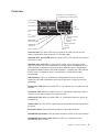 15
15
-
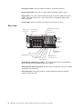 16
16
-
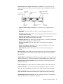 17
17
-
 18
18
-
 19
19
-
 20
20
-
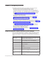 21
21
-
 22
22
-
 23
23
-
 24
24
-
 25
25
-
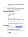 26
26
-
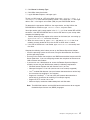 27
27
-
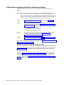 28
28
-
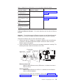 29
29
-
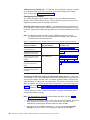 30
30
-
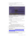 31
31
-
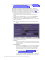 32
32
-
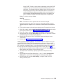 33
33
-
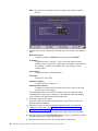 34
34
-
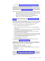 35
35
-
 36
36
-
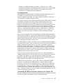 37
37
-
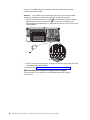 38
38
-
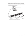 39
39
-
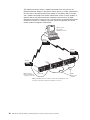 40
40
-
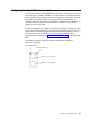 41
41
-
 42
42
-
 43
43
-
 44
44
-
 45
45
-
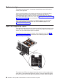 46
46
-
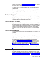 47
47
-
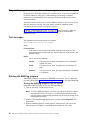 48
48
-
 49
49
-
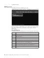 50
50
-
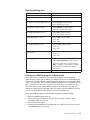 51
51
-
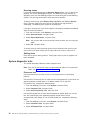 52
52
-
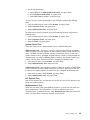 53
53
-
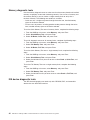 54
54
-
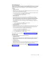 55
55
-
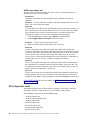 56
56
-
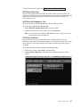 57
57
-
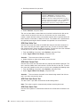 58
58
-
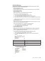 59
59
-
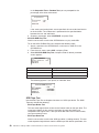 60
60
-
 61
61
-
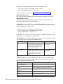 62
62
-
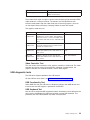 63
63
-
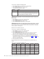 64
64
-
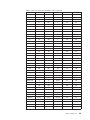 65
65
-
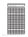 66
66
-
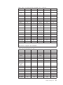 67
67
-
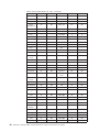 68
68
-
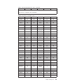 69
69
-
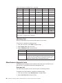 70
70
-
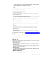 71
71
-
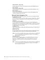 72
72
-
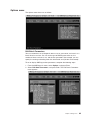 73
73
-
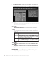 74
74
-
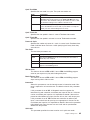 75
75
-
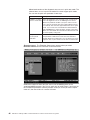 76
76
-
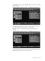 77
77
-
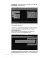 78
78
-
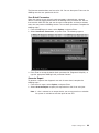 79
79
-
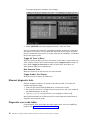 80
80
-
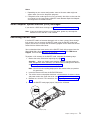 81
81
-
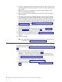 82
82
-
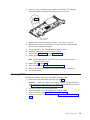 83
83
-
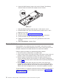 84
84
-
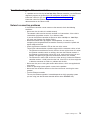 85
85
-
 86
86
-
 87
87
-
 88
88
-
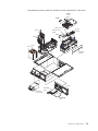 89
89
-
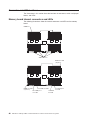 90
90
-
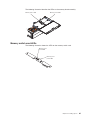 91
91
-
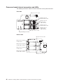 92
92
-
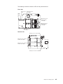 93
93
-
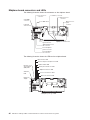 94
94
-
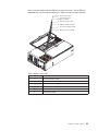 95
95
-
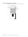 96
96
-
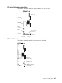 97
97
-
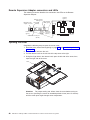 98
98
-
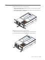 99
99
-
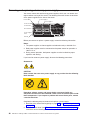 100
100
-
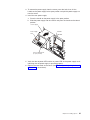 101
101
-
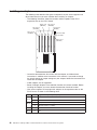 102
102
-
 103
103
-
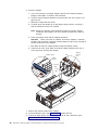 104
104
-
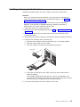 105
105
-
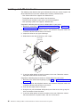 106
106
-
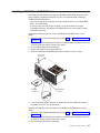 107
107
-
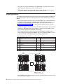 108
108
-
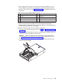 109
109
-
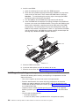 110
110
-
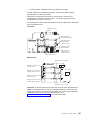 111
111
-
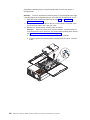 112
112
-
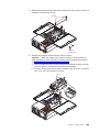 113
113
-
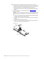 114
114
-
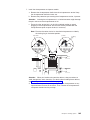 115
115
-
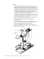 116
116
-
 117
117
-
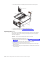 118
118
-
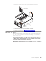 119
119
-
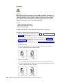 120
120
-
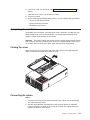 121
121
-
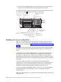 122
122
-
 123
123
-
 124
124
-
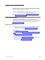 125
125
-
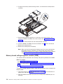 126
126
-
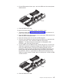 127
127
-
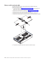 128
128
-
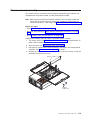 129
129
-
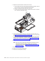 130
130
-
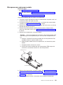 131
131
-
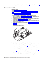 132
132
-
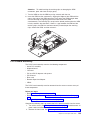 133
133
-
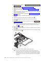 134
134
-
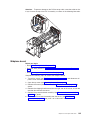 135
135
-
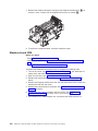 136
136
-
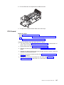 137
137
-
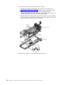 138
138
-
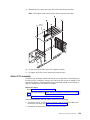 139
139
-
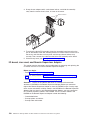 140
140
-
 141
141
-
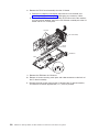 142
142
-
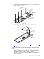 143
143
-
 144
144
-
 145
145
-
 146
146
-
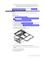 147
147
-
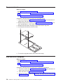 148
148
-
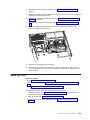 149
149
-
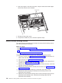 150
150
-
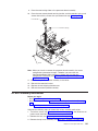 151
151
-
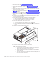 152
152
-
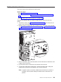 153
153
-
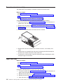 154
154
-
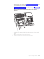 155
155
-
 156
156
-
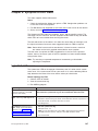 157
157
-
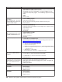 158
158
-
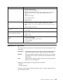 159
159
-
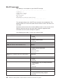 160
160
-
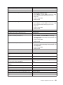 161
161
-
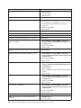 162
162
-
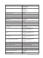 163
163
-
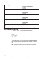 164
164
-
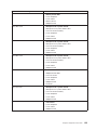 165
165
-
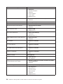 166
166
-
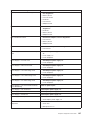 167
167
-
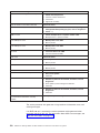 168
168
-
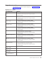 169
169
-
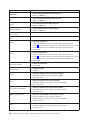 170
170
-
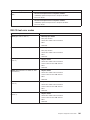 171
171
-
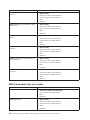 172
172
-
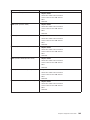 173
173
-
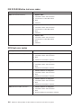 174
174
-
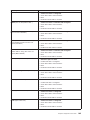 175
175
-
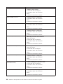 176
176
-
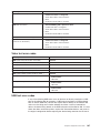 177
177
-
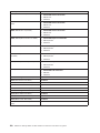 178
178
-
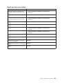 179
179
-
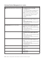 180
180
-
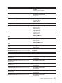 181
181
-
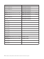 182
182
-
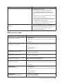 183
183
-
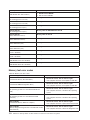 184
184
-
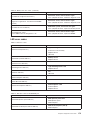 185
185
-
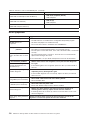 186
186
-
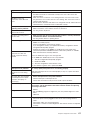 187
187
-
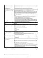 188
188
-
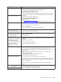 189
189
-
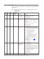 190
190
-
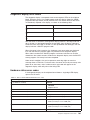 191
191
-
 192
192
-
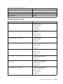 193
193
-
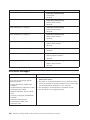 194
194
-
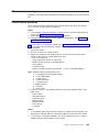 195
195
-
 196
196
-
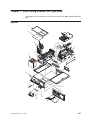 197
197
-
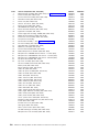 198
198
-
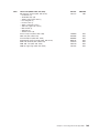 199
199
-
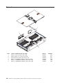 200
200
-
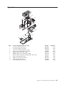 201
201
-
 202
202
-
 203
203
-
 204
204
-
 205
205
-
 206
206
-
 207
207
-
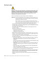 208
208
-
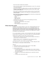 209
209
-
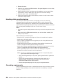 210
210
-
 211
211
-
 212
212
-
 213
213
-
 214
214
-
 215
215
-
 216
216
-
 217
217
-
 218
218
-
 219
219
-
 220
220
-
 221
221
-
 222
222
-
 223
223
-
 224
224
-
 225
225
-
 226
226
-
 227
227
-
 228
228
-
 229
229
-
 230
230
-
 231
231
-
 232
232
-
 233
233
-
 234
234
-
 235
235
-
 236
236
-
 237
237
-
 238
238
-
 239
239
-
 240
240
-
 241
241
-
 242
242
-
 243
243
-
 244
244
-
 245
245
-
 246
246
-
 247
247
-
 248
248
-
 249
249
-
 250
250
-
 251
251
-
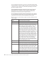 252
252
-
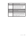 253
253
-
 254
254
-
 255
255
-
 256
256
-
 257
257
-
 258
258
-
 259
259
-
 260
260
-
 261
261
-
 262
262


IBM 8688 Manuale utente
- Tipo
- Manuale utente
- Questo manuale è adatto anche per
in altre lingue
- English: IBM 8688 User manual
Documenti correlati
Altri documenti
-
Lenovo 6290 Hardware Maintenance Manual
-
Intel SR1625UR - Server System - 0 MB RAM Manuale utente
-
Lenovo Aptiva 2274 Hardware Maintenance Manual
-
-
-
Quantum Scalar Key Manager Manuale utente
-
HP ProLiant DL120 G6 Manuale utente
-
-
Gateway E-1600 System Manual
-