Normstahl Magic 1000 Manuale utente
- Categoria
- Apriporta da garage
- Tipo
- Manuale utente

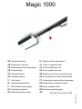
Magic 1000
DE Garagentorantrieb PL Napęd do bram garażowych
GB Garage door operator SI Pogon za garažna vrata
FR Motorisation de porte de garage CZ Pohon garážových vrat
SE Portautomatik SK Pohon garážových brán
DK Garageportmotor GR Μηχανισμός κίνησης γκαραζόποτρας
NO Garasjeportåpner ES Accionamiento de la puerta de garaje
FI Ovikoneisto PT Automatismo para portões de garagem
NL Garagedeuraandrijving BG Задвижване на гаражна врата
IT Motorizzazione per garage HR Pogon garažnih vrata
HU Garázskapu-hajtómű RO Acţionare poartă de garaj
RU Привод гаражных ворот AE
ΕΎΟήΠϟ ΕΎΑϮΑ ϚϳήΤΗ ϡΎψϧ
N000925 12/2010

8 / 214 N000925 12/2010 Magic 1000
GB English
Translation of the German original operating manual
Table of contents
1 Introduction 8
2 Product description 8
3 Symbols 8
4 Intended usage, Guarantee 8
5 Informal Safety Measures 8
6 Safety instructions 8
7 Installation precautions 9
8 Safety devices of the door operator 9
9 Safety inspection 9
Checking load switch-off
Emergency release
Additional safety devices
10 Controls and indicators 9
11 Connections 9
12 Installation preparations 10
13 Installation 10
14 Commissioning 10
15 Teaching in the door operator 10
Teaching in with a remote transmitter
Teaching in without a remote transmitter
16 Teaching in/deleting a remote transmitter 10
17 Operation 11
18 Programming 11
19 Reset 12
20 Attaching additional safety devices 12
Photo cell
EMERGENCY stop
21 Additional connections 12
Additional lighting
External pulse input
Additional antenna
22 Troubleshooting 13
Causes of errors/Remedies
Display / check radio level
Changing the battery of the remote transmitter
23 Maintenance intervals 14
24 Declaration of conformity 14
25 Technical data 14
26 Replacement parts 14
27 Accessories (optional) 14
28 Removal, Disposal 14
Read operating instructions carefully before installing and
commissioning. Pay attention to the illustrations and all notes.
The remote transmitter supplied is taught in to the door
operator.
Packaging: Only reusable materials are used. Dispose of
packaging in an environmentally-friendly way and according
to local legal guidelines.
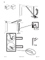
Scope of delivery see page 169
The following symbols are used in this manual:
CAUTION Warns of potential injury and material
damage. Non-observance of instructions marked with
these symbols can result in serious injuries and
material damage.
NOTE: Important technical instructions that must be
observed.
This door operator is suitable for use in domestic garages.
Any other use is deemed incorrect.
This product must not be used in explosion-protected
atmospheres.
The manufacturer must provide written and express approval
for:
• Modifications or attachments
• Use of parts other than factory authorised replacement
parts
• Repairs performed by persons or businesses that have not
been authorised by the manufacturer.
If approval is not obtained for any of the above, this may
invalidate the product’s guarantee.
We will not be liable for damage
• Due to non-compliance with operating instructions
• Due to technical errors in connecting the door operator and
structural deformations that may occur during operation
• As a result of inappropriate door maintenance.
door maintenance.
Keep the operating instructions handy for future use.
The inspection and testing log book provided must be filled
out by the person carrying out the installation and kept by the
operator along with all other documentation (door, door
operator).
General safety instructions
The door operator may only be used if the entire range
of motion is clearly visible. Be mindful of others within the
action range of this product during operation.
Always disconnect the electrical power before working on the
door operator.
Actions prohibited during use of a door operator:
• Passing or driving underneath a moving door
• Lifting of objects and/or persons with the door
• Children must not be left to operate the product
unsupervised; it is not a toy.
The door must only be operated when
• all users are familiar with its functions and operation.
• the door meets the requirements of European standards
EN 12604, EN 12605 and DIN EN 13241-1.
• the door operator is installed in compliance with the
relevant standards (EN 12453, EN 12445 and EN 12635).
• any optional safety devices such as a photo cell,
optosensor or safety rail are fully functional.
• garages without a second entrance have an emergency
lock release from the outside. It may be ordered separately
if necessary.
• an inset door in the garage door is closed and is equipped
with a safety device that prevents activation when the door
is open.
• an additional safety device (safety rail, etc.) has been
installed prior to activation of the automatic closure
function.
• If a person with restricted physical, sensory or mental
capacity, or a person with little experience and/or
1 Introduction
2 Product description
3 Symbols
4 Intended usage, Guarantee
5 Informal Safety Measures
6 Safety instructions

Magic 1000 N000925 12/2010 9 / 214
knowledge of the door operator is to use the device, they
must be supervised by a person who assumes
responsibility for their safety.
Installation must be performed by qualified service
technician.
Work on the electrical installation must only be carried out by
authorised specialist personnel.
The load capacity and suitability of the supporting
construction of the building in which the door operator is to be
installed must be inspected and approved by an expert.
The door operator must be fully and securely attached at all
fastening points. All fastening materials must be selected
according to the nature of the supporting construction and
they must be able to withstand traction force of 900 N.
In the event of non-conformance with these
requirements, there is a risk of injury and material
damage caused by a falling operator or an uncontrolled
movement of the door.
When drilling the fastening holes, do not damage the building
structure or any electrical, water or other lines.
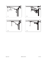
After lifting up the door operator to the ceiling, fasten it fully
with appropriate tools to prevent it from falling down. See
illustration on page 166.
Please observe appropriate industrial safety regulations and
keep children away during installation.
The door operator has the following safety devices. Do
not remove them or alter their functionality.
• Automatic load switch-off during functions "OPEN" and
"CLOSE"
• Connection for photo cell / safety rail / optosensor
• EMERGENCY stop connection: Connection of a switch
(optional) to an inset door mounted in the garage door, for
example
• Emergency release (see page 168 (J))
Checking load switch-off
The automatic load switch-off is a clamping and safety
mechanism that is designed to prevent accidents due to a
moving door.
Stop the door from outside with both hands at waist height.
When closing:
The door must stop automatically and reverse a little if it
comes into contact with an obstruction.
When opening:
The door must stop automatically when it meets with
resistance (if menu A7 = 001, it moves back a short distance).
After load switch-off, the door operator lights flash until the
next pulse or wireless command is received.
Emergency release
Check as per the information provided on page 168 (J).
Additional safety devices
Check for proper functioning as per the manufacturer’s
instructions.
Messages of the indicator lamp (8)
7 Installation precautions
8 Safety devices of the door operator
9 Safety inspection
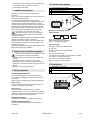
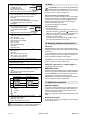
10 Controls and indicators
5 Pushbutton Close door / Minus
6 Pushbutton Menu / Confirm (Teach-in run)
7 Pushbutton Open door / Plus
8 Indicator lamp
Status messages
A door in end position OPEN
B door between the two end positions
C door in end position CLOSED
Status messages
During door movement in OPEN direction
C => B => A...
During door movement in CLOSE direction
A => B => C...
L4 Set end position OPEN
L3 Reference run CLOSE and set end position CLOSED
L2 Teach-in run OPEN (load values)
L1 Teach-in run CLOSE (load values)
Err Error and error number (flashing)
11 Connections
1 EMERGENCY stop (green)
2 Photo cell (yellow)
3
Function programmable, see Chapter 18, C4
4
567
8
1342

10 / 214 N000925 12/2010 Magic 1000
Please note: Check that the door is working properly
and running smoothly, and adjust if necessary. The
spring tension of the door must be set in such a way that it is
stable and can be opened and closed by hand smoothly and
without jolting.
• Standard and appropriate shock-proof socket approx. 10 -
50 cm away from the fastening position for the head of the
operator.
(For information on fuses, see the technical data.)
• Only install the door operator in dry garages.
Make sure the installation set for the connection is ready on
the door type that is being attached and/or install it according
to the relevant manual.
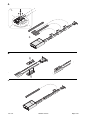
See instructions for installation on page ff 162.
The head of the operator can be turned by 90° to the rail
runner respectively as required (see page 162 (A)).
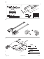
Installation step D, page 163:
1. Tighten the toothed belt’s clamping nut until the toothed
belt no longer rests on the guide rail (equivalent to
dimension X).
2. Use the clamping nut (dimension B) to increase the
toothed belt tension to correspond to the length of the door
operator.
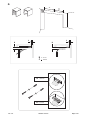
Installation step G, page 165, installation dimensions:
Once installation is complete
• Slowly open the door by hand until you hear the slide snap
in.
• Connect to mains, display shows L4 and the door operator
lamp flashes at intervals of 4.
• Teach in the door operator (see Chapter 15).
• Teach in the remote transmitter (see Chapter 16).
• Carry out a safety inspection (see Chapter 9).
ATTENTION: No protection is provided by the load
switch-off whilst the door operator is being taught
in.
Note: Teaching in is only possible during initial installation or
after resetting the door operator. Do not press any keys
during the teach-in procedure.
Preparation: Connect the door to the door operator.
Teaching in with a remote transmitter
At the time of delivery and after resetting the door
operator, the remote transmitter supports the following
functions:
• A Safety control operation and fine adjustment "OPEN"
• B Safety control operation and fine adjustment "CLOSE"
• C and D Confirmation (storage)
Once the door operator has been taught
in, key A is used for remote control and
the other keys can be used to control
other similar door operators or other
radio receivers.
Teaching in
• Press and hold down key A; the door
moves in the open direction.
• When you reach the desired end position "OPEN", release
key A. (You can make corrections with key B.)
• Press key C once briefly, teach-in procedure: The door
operator automatically stores "End position OPEN/CLOSE"
and the loads of the "Travel path OPEN/CLOSE". The door
operator lights flash in synchronism.
Teach-in is complete when the door is open and the door
operator lights are on.
Check load switch-off according to Chapter 9,Safety
inspection.
Teaching in without a remote transmitter
On the door operator:
• Press and hold pushbutton and the door moves in the
open direction. Release pushbutton when the desired
opening position is reached. A correction can be made with
the pushbutton .
• Press the Menu pushbutton , the door operator
automatically stores "End position OPEN/CLOSE" and the
loads of the "Travel path OPEN/CLOSE" . The door
operator lights flash in synchronism.
Teach-in is complete when the door is open and the door
operator lights are on.
Check load switch-off according to Chapter 9,Safety
inspection.
Programming the remote transmitter:
During one of the 3 status messages A, B or C (seeChapter
10), press the pushbuttons and simultaneously
(approx. 1 s), F0 flashes in the display.
Select the desired function with the pushbuttons and .
Press the desired key on the remote transmitter, the radio
command is taught in.
Note: The number of the function is shown in the display
during the transmission pulse.
12 Installation preparations
13 Installation
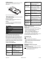
Overhead Sectional Doors
Fig.
Low lintel Dimension G
Euro 30 - 50mm G2
G60 20 - 40mm G3
G60 Max 30 - 50mm G1
Normal lintel
Euro 100 - 120mm G2
G60 100 - 120mm G3
G60 Max 100 - 120mm G1
One-Piece-Door 20 - 40mm G4
14 Commissioning
15 Teaching in the door operator
16 Teaching in/deleting a remote
transmitter
Functions
F0 OPEN / Stop / CLOSE
F1 OPEN / Stop / OPEN
F2 CLOSE / Stop / CLOSE
F3 Stop
F4 Partial opening
F5 Light ON (restart light time)
F6 Light ON / OFF
F7 OPEN
F8 Close

Magic 1000 N000925 12/2010 11 / 214
Deleting (all) remote transmitter(s):
During one of the 3 status messages A, B or C (seeChapter
10), press the pushbuttons and simultaneously for >6
seconds, FL flashes in the display. The status message
reappears after 3 seconds.
CAUTION: Mishandling the product can result in
injuries or material damage. Follow the basic safety
rules:
When opening or closing the door, do not block the interior or
exterior swivel ranges. Keep children away.
The door movements can be activated or stopped using the
remote transmitter provided or via switching elements such
as the wall keypad, which can be connected if desired.
Optional external features (such as the EMERGENCY
STOP) can also be connected to the door operator.
The operator must be connected to a door before
it is used. If it is not, incorrect load values will be
taught in to the electronic system. This can cause
malfunctions.
Switch on programming mode
During one of the 3 status messages A, B or C (seeChapter
10) press the Menu pusbutton for longer than 1.5
seconds. The display changes to the menu (D).
Select programming menu
Select the desired menu with the pushbuttons and .
Show / change menu value
Displays: Press the Menu pushbutton for less than 1.5
seconds, the menu value (E) is displayed.
Change: Change the value with the pushbuttons and .
Save: Press the Menu pushbutton for less than 1.5
seconds, the programming menu (D) is displayed.
Exit programming mode
Press the Menu pushbutton for longer than 1.5 seconds,
the display changes to the status message, changes are
saved.
If no key is pressed within 15 seconds during programming, it
automatically exits the programming mode.
ATTENTION: If the values of the programming
menu A0 to A4 are changed, the load switch-off no
longer provides any protection! Teach the door operator in
again before re-commissioning. For this carry out Teaching in
the door operator (Chapter 15) .
17 Operation
18 Programming
Factory setting
Menu
Function, setting range, unit
A0 Length SOFT RUN OPEN in 7cm
000..009
002
A1 Length SOFT RUN CLOSE in 7cm
000..009
004
A2 Soft running speed (CLOSE) mm/s
000= 50...009= 140
005
A3 Backjump, OFF= 000 ON= 001 001
A4 Change in direction, OFF= 000 ON= 001
Setting (with +/-) only possible if EMERGENCY
STOP plug (1, green) is unplugged.
000
A5 Added load OPEN
1)
000..009 003
A6 Added load CLOSE
1)
000..009 003
A7 Door type: Overhead sectional door/one-piece
door = 000
Side sectional door* = 001
Side sectional door with soft start = 002
* Obstruction release also in OPEN direction
000
A8 Warning time (OPEN/CLOSE) 001=2sec...
008=16sec
000
A9 Accessory card
000= ZKMagicS
001= ZKMagic
000
b0 Relay 1 (with ZKMagic accessory card)
000= no function
001= E-lock
002= warning light *
002= photo cell test* (interruption transmitter
voltage)
004= status display*: Door in end position OPEN
005= status display*: Door in end position
CLOSED
006= green light*
007= red light*
* if A9= 001
000
b1 Relay 2 (with ZKMagic accessory card)
000= no function
001= E-lock*
002= warning light *
002= photo cell test* (interruption transmitter
voltage)
004= status display*: Door in end position OPEN
005= status display*: Door in end position
CLOSED
006= green light*
007= red light*
* if A9= 001
000
b2 Closing edge protection, for accessory card
ZKMagic and if A9= 001
000= OFF 001= OSE 002= 8k2
000
b3 Empty run detection 000= OFF 001= ON 001
b4 Automatic closing
1)
*, secs. and min.
000= OFF
001.0.010 keep-open time secs.*
(001 = 5secs... 010 = 50secs)
011..040 keep-open time min*
(011=1min... 040=30min) * plus warning time
* only active if door was fully opened
000
b6 Maintenance interval
000= OFF
001..009 (1,000 door movements)
Example: 005 = 5,000 door movements
The operator lighting flashes after every door
movement when the maintenance interval has run
out. A misadjustment resets the counter of the
maintenance interval.
000

12 / 214 N000925 12/2010 Magic 1000
1)
If the added load (A5, A6) is >003 and/or the
automatic closing (b4, c1) is set to ON (>000), the door
may only be operated with an additional safety device.
ATTENTION: There is no longer any protection by
switching off the load after the reset. Teach the door
operator in again before re-commissioning. For this carry out
Teaching in the door operator (Chapter 15) .
Reset (saved values of the teach-in runs)
During one of the 3 status messages A, B or C (see Chapter
10) press the pushbuttons and Menu simultaneously
for longer than 8 seconds and less than 10 seconds. The
indicator lamp flashes(rES), then the status message is
displayed; the reset is carried out.
The remote transmitters are not deleted.
Reset, factory setting
• Pull out the plug (1).
• During one of the 3 status messages A, B or C (see 10)
press the pushbuttons and Menu simultaneously for
longer than 12 seconds. The indicator lamp flashes slowly
at first, then quicker (rES). Then the status display
reappears, the reset is made.
The values shown under Programming (Chapter 18) are
set. The remote transmitters are not reset.
Photo cell
Function: When the safety input is activated (opening the
contact) the operator stops and reverses as far as the OPEN
end position.
If the “automatic closure” function is also activated, following
the third successive obstruction message, the operator will
move to the OPEN end position and shut down.
Connection: Pull out plug with yellow bridge on the external
junction 2 and store it. Plug on safety device.
Safety rail, opto-sensor and warning light are
connected by extension modules.
EMERGENCY stop
Function: If the external safety device is operated when the
door is moving (Contact opened), the door stops immediately.
Once the EMERGENCY stop contact has closed, the door
operator can be moved again with the next pulse.
Connection: Pull out plug with green bridge on the external
junction 5 and store it. Plug on safety device.
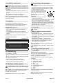
Additional lighting
Connection must be performed only by qualified electricians.
In addition to the operator light (40W), optional lighting of a
maximum of 60 W (no tubular fluorescent lamps) can be
connected to terminals 1 and 2.
Note: Some energy-saving lamps can interfere with the radio
signal.
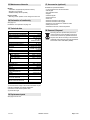
External pulse input
An external pulse signal (e.g. wall button) can be connected
to terminals 14 and 15.
b7 Version number
Each of the digit positions (0-7)
is displayed in turn.
The example shows:
Version: 04 Date: 20.05.10
Select the position with the pushbuttons and .
b8 Service mode
000= control panel free, menu items adjustable
001= control panel locked, menu items not
adjustable
002= data output (accessory card)
Setting only possible if EMERGENCY STOP plug
(1, green) and photo cell (2, yellow) are
unplugged.
000
b9 Run counter (not adjustable)
Each of the digit positions (0-5)
is displayed one after another.
The example shows the value
8,000
Select the position with the pushbuttons and .
C0 Test mode for Magic-Door-Control (option)
Radio signal, maximum 15 seconds:
000= no signal
001= end position OPEN
002= end position CLOSED
003= run open
004= run close
005= standstill underway
007= error
008= obstruction
000
C1 Automatic closing from partial opening
1)
secs and mins
000= OFF
001.010 keep-open time secs.*
(001 = 5secs... 010 = 50secs)
011..040 keep-open time min*
(011=1min... 040=30min) * plus warning time
000
C2 Partial opening in 5cm steps 000..100 020
C3 Lighting time, after motor running
000..060 (10sec. steps)
012
C4 Close after leaving the photo cell, 000..0.019, 0.5
s
000
C5 EMERGENCY stop input
000= automatic closing after EMERGENCY STOP
locked
001= closing time starts again after release
EMERGENCY stop
000
C6 Function connections 000
C7 PARKING ASSISTANT operator light flashes
when door can be closed
000= OFF 001= ON
(only in connection with photo cell)
000
04200510
01234567
008000
012345
Connection 3 Connection 4
000 Partial opening
001
002
003
OPEN
CLOSE
Stop
STOP STOP
STOP STOP
STOP STOP
STOP STOP
STOP STOP
STOP
19 Reset
20 Attaching additional safety devices
21 Additional connections

Magic 1000 N000925 12/2010 13 / 214
Additional antenna
An external antenna can be connected to terminals 17 and 16
(GND). The internal antenna (terminal 17) must be
disconnected.
Figure: Control board See also page 171.
Interference frequencies
The wireless signals of other 433 MHz transmitters can
interfere with the door operator.
Self-test
The system runs a self-test after initialisation, after each
motor operation and after every 2.25 hours in idle mode.
Error free = status message.
Troubleshooting: Reset (Chapter 19) and then perform work
step Teaching in the door operator (Chapter 15).
If the error occurs again, request customer service.
Note: If the same error occurs in two successive self-tests,
the control system will be disabled (commands are rejected).
After approximately one further minute, the system runs
another self-test. If no errors are detected, the control system
is enabled again. If the error persists, a reset will need to be
performed. This will delete all settings and the door operator
will have to be taught in again.
Causes of errors/Remedies
Display / check radio level
The signal strength of the received radio signal can be
displayed, for this:
• During one of the 3 status messages A, B or C (seeChapter
10), press the pushbuttons and simultaneously
(approx. 1 s), F0 flashes in the display.
• Press the two buttons again simultaneously
(approx. 1 sec), the radio level display is activated.
x=1 no radio signal ...x=8 high signal strength
The radio level display remains activated until the two buttons
are pressed again simultaneously (approx. 1 sec.).
Changing the fuse
Pull out mains plug.
• Remove the operator hood, see page 171.
• Remove the faulty fuse (S1) from the fuse holder (S2) and
replace it. Make sure that the new fuse has the correct
value!
• Replace the operator hood.
Restore the mains connection.
Changing the battery of the remote
transmitter
Open the housing cover. Remove the battery, fit a new one
and replace the housing cover.
Use only leak-proof batteries. Make sure the polarity
is correct. Dispose of used batteries in an
environmentally-friendly way.
22 Troubleshooting
Error messages*
002 EEprom data
003 Current measurement
004 Hardware Photo cell
005 Switch off thyristors
006 Switch off relay
007 Watchdog test
008 ROM test
009 RAM test
010 SD test
Description Possible cause/Remedy
Door operator light
flashes evenly
The door has hit an obstruction, do
function test
Door operator light
flashes at intervals of
4
Door operator is not taught in,
attention no protection by load
switch-off! Carry out door operator
Teaching in the door operator
(Chapter 15)
Entrapment
protection device not
working.
Incorrect setting of door or
entrapment protection device /
Reset and teach in again
The operator is not
working at all.
None or wrong voltage supply / The
fuse of the motor control is defective
/ Check external terminals 7 and 8.
1
2
16
15
14
17
The operator is
defective.
The slides are not snapped-in
properly./The toothed belts are not
tensioned correctly./The door
thresholds are frozen.
Operator closes the
door slowly (soft
start) whilst door
operator light flashes
Operator teaches in the travel
automatically. After CLOSED end
position, moves automatically to
OPEN end position. If the door
operator light flashes in intervals of
4, carry outTeaching in the door
operator (Chapter 15)
The operator
switches off during
motion.
Check that the door is running
smoothly and that the entrapment
protection device is working properly
/ Reset / Teach in the door operator
Remote transmitter is
not working, LED not
alight
Replace the batteries
Remote transmitter is
not working
If the function message assigned to
the transmission pulse is not
displayed whilst the transmitter is
actuated (see Chapter 16): Teach in
remote transmitter / Poor reception
(install optional antenna)
The operator cannot
be used via the wall
keypad (optional).
Check the wall keypad and control
wire.
The operator cannot
be used via the
remote transmitter
(optional).
Radio level too weak. There are
interfering radio signals from other
transmission sources / Carry out
radio level check as described below

14 / 214 N000925 12/2010 Magic 1000
Monthly
• Load switch-off (entrapment protection device)
• Emergency lock release
• Additional safety devices (if fitted)
Every 6 months
• Mounting of door operator on the ceiling and on the wall
See page 174.
Declaration of incorporation see page 175.
1) The transmission range of the remote transmitter may be
reduced considerably by external interference.
2) Dimensions with turned operator head
3) plus stroke length
See pages 169 and 170.
Available from specialised dealer's:
• 4-command multi-use remote transmitter
• Wall keypad
• Key-operated control
• Keypad
• Wireless keypad
• External antenna
• Photo cell
• Extension module for opto-sensor
• Extension module for warning light
• Emergency lock release from outside or inside
• Safety rail 8.2 kohms
• Potential-free receiver, various frequencies
Removing the door operator takes place in the
reverse sequence of the installation instructions
and must be carried out by qualified technicians.
Dispose of the device according to environmental
guidelines. Electrical parts must not be disposed of
as domestic waste. 2002/96/EG (WEEE)
23 Maintenance intervals
24 Declaration of conformity
25 Technical data
Mains connection 230 V~, 50/60 Hz
Device fuse 2x 1.6 A, T (slow-blow)
Power consumption at rated load 170 W
Closed current < 2 W
Degree of protection For dry rooms
only, IP 20
Protection class 1
Wireless remote control 433.92 MHz AM
Remote transmitter range 1) 15 - 50 m
Remote transmitter batteries CR 2032 (3 V)
Idle speed ~ OPEN >210 mm/s
~ CLOSE >140 mm/s
Traction 1,000 N
Rated load 300 N
Stroke length
Magic 1000 2890 +/- 25 mm
Magic 1000 long 3978 +/- 25 mm
Magic 1000 size 3 5066 +/- 25 mm
Magic 1000 size 4 7242 +/- 25 mm
Total length 3) 615 +/- 25 mm
Total length 2) 3) 485 +/- 25 mm
Width 285 mm
Width 2) 363 mm
Installation height 40 mm
Permissible
ambient temperatures
-20°C to 50 °C
Storage -20°C to 80 °C
Lighting E14, max. 40 W
Maximum number of duty cycles
per hour at rated load
20
Maximum number of duty cycles
without a break at rated load
8
Noise level at a distance of 2 m ≤69 dB(A)
26 Replacement parts
27 Accessories (optional)
28 Removal, Disposal

162 / 214 N000925 12/2010 Magic 1000
A
B
C
?
2.
1.

Magic 1000 N000925 12/2010 163 / 214
D
E
F
A
BX
1.
1. 2.
A
mm
3.492
4.580
5.668
7.844
4-6
6-9
9-11
12-15
Bmm
0-35cm
3.492 mm
4.580 mm
5.668 mm
7.844 mm

164 / 214 N000925 12/2010 Magic 1000
G
=
=
A
B 5-15mm
C > 100 mm
B
C
B
C
A < 150 mm
A >150 mm

Magic 1000 N000925 12/2010 165 / 214
Einbaumaße
D
G3
G2
D
D
G4
D
G1
N001452

166 / 214 N000925 12/2010 Magic 1000
H
A
A 100 - 150 mm
A 150 - 350 mm

Magic 1000 N000925 12/2010 167 / 214
I
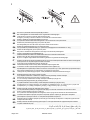
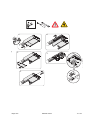
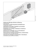
DE
Das zum Tor passende Toranschlussprofil (X) montieren.
Bei notentriegeltem Tor besteht Gefahr durch ungebremste Torbewegungen.
GB
Install the door connection profile (X) that matches the door.
Emergency unlocking of the door creates an unchecked door movement hazard
FR
Monter le profilé de raccordement adapté à la porte (X).
Une porte ainsi déverrouillée devient dangereuse : ses mouvements ne sont plus freinés.
SE
Montera den portanslutningsprofil (X) som passar till porten.
På nödupplåsta portar finns det risk för att portens rörelser inte bromsas in.
DA
Monter den porttilslutningsprofil (X), som passer til porten.
Vær opmærksom på eventuelle fare p.g.a. portens frie bevægelighed når nødudløseren er i brug.
NO
Monter den tilkoblingsprofil (X) som passer til porten.
Når porten er frikoblet kan det oppstå fare som følge av ukontrollerte portbevegelser.
FI
Oveen on asennettava sopiva liitäntäprofiili (X).
Hätäavaustilanteessa saattaa oven hallitsematon liikkuminen vaarantaa turvallisuuden.
NL
Monteer het bij de deur passende deuraansluitprofiel (X).
Bij een in noodgeval ontgrendelde deur bestaat er gevaar door ongeremde deurbewegingen.
IT
Montare il profilo idoneo del raccordo della porta (X). Se la porta è stata aperta azionando lo sblocco d’emergenza,
esiste il pericolo che la porta esegua movimenti non frenati.
HU
A kapuhoz illõ kapucsatlakozási profilt (X) szereljen fel.
Vészkireteszelt kapu esetén veszély áll fenn fékezetlen kapumozgások által.
RU
Установить соответствующии воротам присоединительныи профиль (X).
При аварийном отпирании ворот имеется опасность вследствие отсутствия торможения при движении ворот.
PL
Zamontować kształtownik do mocowania bramy (X) pasujący do typu bramy.
Jeżeli garaż nie posiada drugiego wejścia, należy zainstalować zewnętrzne otwieranie awaryjne.
SI
Montirajte priključni profil vrat (X) primeren za vrata.
Če je odpiralni mehanizem v sili aktiviran, obstaja nevarnost pomikanja vrat brez zaviranja.
CZ
Namontovat pripojovací profil vrat, který se hodí pro vrata.
U vrat s nouzovým odblokováním existuje nebezpečí nebržděnými pohyby vrat.
SK
Namontuje profil pripojenia brány (X) vhodný pre bránu.
V prípade núdzového otvorenia brány vzniká nebezpečie nebrzdených pohybov brány.
GR
Συναρμολογήστε το προφίλ τελειώματος που ταιριάζει στη γκαραζόπορτα (X). Σε περίπτωση που η πόρτα είναι
απασφαλισμένη με τη διάταξη απασφάλισης ανάγκης, υπάρχει κίνδυνος λόγω μη πέδησης
ES
Montar el perfil de conexión (X) adecuado para la puerta.
Con la puerta desbloqueada por emergencia existe peligro a causa de movimientos sin freno de la misma.
PT
Monte o perfil de ligação certo para o portão (X).
Se o portão tiver sido desbloqueado de emergência, existe o perigo de ele se deslocar descontroladamente.
BG
Указание: Монтирайте подходящ за вратата свързващ профил за врата (X). При врати с аварийно
деблокиране съществува опасност от неограничени движения на вратата.
HR
Montirajte vratima pripadajući priključni profil vrata (X). Kod vrata koja su otključana u nuždi postoji opasnost radi
kretanja vrata bez kočenja.
RO
Montaţi profilul de racordare poartă (X) potrivit porţii. În cazul porţii deblocate de urgenţă există pericol datorat
mişcărilor nefrânate ale porţii.
AE
ΔΑϮΒϠϟ ΔϠϣήϔϤϟ ήϴϏ ΔϛήΤϟϝϼΧϦϣήτΧ ΪΟϮϳ ϪϧΈϓ ΉέϮσΔϟΎΣϲϓΎϫήϳήΤΗ ϢΗ Ϊϗ ΔΑϮΒϟϥϮϜΗΎϣΪϨϋ
ΔΑϮΒϟ ϞϴλϮΗ ϊτϘϣ ΐϴϛήΗ ϢΘϳ(X)ΔΑϮΒϠϟΐγΎϨϤϟ.

168 / 214 N000925 12/2010 Magic 1000
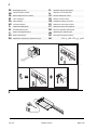
J
K
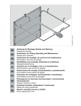
DE
Notentriegelung intern
PL
Otwieranie awaryjne wewnętrzne
GB
Internal emergency release
SI
Odpiranje v sili z notranje strani
FR
Déverrouillage de secours interne
CZ
Nouzové odblokování. Vnitřní
SE
Intern nödöppning
SK
Núdzové otvorenie interné
DA
Intern frikobling
GR
Απασφάλιση ανάγκης εσωτερικά
NO
Innvendig nødsperre
ES
Desbloqueo de emergencia interno
FI
Sisällä oleva hätävapautin
PT
Desbloqueio interno de emergência
NL
Noodontgrendeling intern
BG
Вътрешно аварийно деблокиране
IT
Sblocco di emergenza interno
HR
Otključavanje u nuždi od unutra
HU
Belső vészkireteszelő
RO
Deschiderea de siguranţă internă
RU
Аварийное отпирающее устройство изнутри
AE
ΎϴϠΧΩ ΉέϮτϟ ΕϻΎΣϲϓήϳήΤΘϟ

Magic 1000 N000925 12/2010 169 / 214
Lieferumfang
9
9
10
10
4.1
4.3
4.2
6
5
2
B
6
1.2
1.3
1.9
1.11
1.4
8
1.6
1.12
1.5
1.8
1.1

170 / 214 N000925 12/2010 Magic 1000
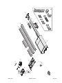
Ersatzteilliste
1.1 N000922-00-00
1.2 N000912-00-00
1.3 T90005
1.4 T14558
1.5 (Stopp) T14743
1.6 (SE) T14742
1.8 N000913
1.9 * N001495-00-00
1.11 *
Schuko 1000 mm N001415-00-00
GB 1000 mm N001415-00-02
GB 5000 mm N001415-00-03
CH 1000 mm N001415-00-01
1.12 *
Euro T14597
GB T14888
2
NS N000880-01-00
CR N000880-02-00
HS N000880-04-00
IN N000880-05-00
NT N000880-06-00
4.1 T14509
4.2 T14600
4.3 N000877-00-00
5
Gr.1 6480 mm N001491-00-00
Gr.2 8664 mm N001492-00-00
Gr.3 10840 mm N001493-00-00
Gr.4 15160 mm N001494-00-00
6 N000907-00-00
8 T14579
9 T14529
10 T14572
B T14526
PL
Części zamienne oznaczone * mogą być wymieniane
tylko przez personel z odpowiednimi uprawnieniami
zawodowymi.
SI
Rezervne dele označene z * smejo zamenjati samo
pooblaščeni strokovnjaki.
CZ
Náhradní díly označené * smí vyměnit jen autorizo-
vaný personál.
SK
Náhradné diely označené * smie vymieňaž výhradne
autorizovaný odborný personál.
GR
Τα σημαδεμένα με έναν αστερίσκο (*) ανταλλακτικά
εξαρτήματα επιτρέπεται να αντικατασταθούν μόνο από
εξουσιοδοτημένο ειδικευμένο προσωπικό.
ES
Las piezas de repuesto marcadas con * solamente las
puede cambiar personal especializado y autorizado.
PT
As peças sobressalentes assinaladas com * só
podem ser substituídas por pessoal técnico autori-
zado.
BG
Отбелязаните с * резервни части могат да се
заменят само от упълномощени специалисти.
HR
Mijenjanje sa * označenih rezervnih dijelova
dopušteno je samo ovlaštenom stručnom osoblju.
RO
Piesele de schimb marcate cu * pot fi schimbate doar
de către personal de specialitate autorizat.
AE
ΓΪϤΘόϣΔμμΨΘϣ ΔϴϨϘΗ ΔϟΎϤϋ.
ΔϣϼόΑ ΓΰϴϤϤϟ έΎϴϐϟ ϊτϗ *ϻ· ΎϫήϴϴϐΘΑ Ϥδϳ ϻ
ϞΒϗ Ϧϣ
DE
Die mit * markierten Ersatzteile dürfen nur durch
autorisiertes Fachpersonal gewechselt werden.
GB
The spare parts marked with * may be exchanged
only by authorised trained personnel.
FR
Le remplacement des pièces de rechange signalées
par * ne doit être effectué que par un personnel
agréé.
SE
De med * markerade reservdelarna får endast bytas
av auktoriserat fackfolk.
DA
De reservedele, som er markeret med *, må kun uds-
kiftes af autoriseret fagpersonale.
NO
Reservedeler som er merket med * må kun skiftes ut
av autorisert fagpersonale.
FI
Tähdellä * merkityt varaosat saa vaihtaa ainoastaan
valtuutettu ammattihenkilöstö
NL
De met * gemarkeerde reserveonderdelen mogen
alleen door geautoriseerd vakpersoneel vervangen
worden.
IT
I ricambi contrassegnati con * possono essere sosti-
tuiti soltanto da personale specializzato autorizzato.
HU
A csillaggal (*) jelölt pótalkatrészeket csak arra feljo-
gosított szakszemélyzet cserélheti ki.
RU
Отмеченные символом * запасные части
разрешается заменять только авторизованным
специалистам.

Magic 1000 N000925 12/2010 171 / 214
Sicherung wechseln
Sicheung wechseln
1.
2.
3.
4.
5.
S1
S2

174 / 214 N000925 12/2010 Magic 1000
EC-Declaration of Conformity
in accordance with the EC-Machinery Directive 2006/42/EG, Appendix II A
GB
Translation of the German declaration
We,
Cardo Door Production GmbH
Normstahlstrasse 1-3
D-85368 Moosburg, Germany
hereby declare that the machinery described below complies in its design and
construction and in the version marketed by us with the basic safety and health
requirements of the EC Directive 2006/42/EG.
Product description
Function Electrical garage door operator with radio remote control
Model Magic
Type Magic 1000
With following garage door types:
Euroclassic Iso - Euroframe alu - Euroframe copper - Euroframe wood - Euroline Iso - Eurostyle iso - Euroflair Iso -
Eurotrend Iso - Eurotwin Iso - Castell - Elegant - Prominent-F - Klassik - Rustico - S-Castell - S-Elegant -
S-Prominent-F - S-Klassik - S-Rustico - Prominent - Variant - S-Variant - Variant wood - S-Variant Wood - Classic - Style -
Twenty - Topframe - Topclassic iso - Topframe Alu - Topframe Copper - Topflair Iso - Topframe Steel - Topframe wood -
Topline Iso - Topstyle Iso - Toptrend Iso - Toptwin Iso - G60 Classic - G60 Style - G60 Trend - G60 Line - G60 Elipse -
Euromax - G60 Max
Harmonised standards applied
DIN EN ISO 12100-1:2004-04 Safety of machinery – basic concepts, general principles for design – Part 1
DIN EN ISO 12100-2/A1:2009-10 Safety of machinery – basic concepts, general principles for design – Part 2
DIN EN ISO 13849-1:2008-12 Safety of machinery – Safety-related parts of control systems - Part 1
DIN EN 12445:2005-05 Industrial, commercial and garage doors and gates – Safety in use of power operated
doors – Test methods
DIN EN 12453:2005-05 Industrial, commercial and garage doors and gates – Safety in use of power operated
doors - Requirements
DIN EN 13241-1:2004-04 Industrial, commercial and garage doors and gates – Product standard – Products
without fire resistance and smoke control characteristics
Other applied directives
Construction Products Directive 89/106/EWG EMC 2004/108/EG
Low Voltage Directive 2006/95/EG 1999/5/EG R&TTE
The following tests were conducted by these approved bodies:
TÜV SÜD Product Service GmbH
Reg. No. 063795
Ridlerstrasse 65 - D-80339 München, Germany
Mikes
Reg. No. D-PL-12030-01-03
Ohmstrasse 2-4 - D-94342 Straßkirchen, Germany
Test results (passed)
- Safety requirements closing forces
- Electrical safety
- Mechanical requirements
- Electromagnetic compatibility
Person authorised to collect the technical documents: Herbert Dust,
address see above.
Wolfgang Schulz, Managing Director
Moosburg, 01.12.10

Magic 1000 N000925 12/2010 175 / 214
Declaration of incorporation
GB
Translation of the German declaration
We,
Cardo Door Production GmbH
Normstahlstrasse 1-3
D-85368 Moosburg, Germany
hereby declare that we have applied and complied with the following basic requirements of the EC Directive 2006/42/EG in the
design and manufacture of the partially completed machinery described below: 1.1.2, 1.1.3, 1.2.1, 1.2.3, 1.2.4, 1.2.6, 1.3.2,
1.3.4, 1.5.1, 1.5.2, 1.5.3, 1.5.8, 1.5.9, 1.5.10, 1.5.11, 1.5.9, 1.6.3, 1.7.3, 1.7.4
The special technical documents have been compiled in accordance with Appendix VII Part B of the EC Directive 2006/42/EG.
We undertake to submit these in electronic form to the market supervisory authorities upon demand within a reasonable time.
Description of the partially completed machinery
Function Electrical garage door operator with radio remote control
Model Magic
Type Magic 1000
Harmonised standards applied
DIN EN ISO 12100-1:2004-04 Safety of machinery – basic concepts, general principles for design – Part 1
DIN EN ISO 12100-2/A1:2009-10 Safety of machinery – basic concepts, general principles for design – Part 2
DIN EN ISO 13849-1:2008-12 Safety of machinery – Safety-related parts of control systems - Part 1
DIN EN 13241-1:2004-04 Industrial, commercial and garage doors and gates – Product standard – Products
without fire resistance and smoke control characteristics
Other applied directives
Construction Products Directive 89/106/EWG EMC 2004/108/EG
Low Voltage Directive 2006/95/EG 1999/5/EG R&TTE
The following tests were conducted by these approved bodies:
TÜV SÜD Product Service GmbH
Reg. No. 063795
Ridlerstrasse 65 - D-80339 München, Germany
Mikes
Reg. No. D-PL-12030-01-03
Ohmstrasse 2-4 - D-94342 Straßkirchen, Germany
Test results (passed)
- Safety requirements closing forces
- Electrical safety
- Mechanical requirements
- Electromagnetic compatibility
The partially completed machinery may not be put into operation until it has been determined that the machinery into which the
partially completed machinery is to be installed complies with the regulations of the Machinery Directive.
Wolfgang Schulz, Managing Director
Moosburg, 01.12.10
-
 1
1
-
 2
2
-
 3
3
-
 4
4
-
 5
5
-
 6
6
-
 7
7
-
 8
8
-
 9
9
-
 10
10
-
 11
11
-
 12
12
-
 13
13
-
 14
14
-
 15
15
-
 16
16
-
 17
17
-
 18
18
-
 19
19
-
 20
20


Normstahl Magic 1000 Manuale utente
- Categoria
- Apriporta da garage
- Tipo
- Manuale utente
in altre lingue
- English: Normstahl Magic 1000 User manual
Altri documenti
-
Hormann Liftronic 800 Manuale del proprietario
-
-
 Hörmann Ecostar LIFTRONIC 500 Manuale del proprietario
-
 Hörmann Ecostar PORTRONIC D5000 Manuale del proprietario
-
 IsoMatic 500 Instructions For Fitting, Operating And Maintenance
-
ADEMCO Security System VISTA-15CN Installation And Setup Manual
-
BFT Eos 1200 U Manuale utente
-
-
Marantec Light 200 Manuale del proprietario
-


