
ISTRUZIONI D’USO E DI INSTALLAZIONE
INSTALLATION AND USER’S MANUAL
INSTRUCTIONS D’UTILISATION ET D’INSTALLATION
INSTALLATIONS-UND GEBRAUCHSANLEITUNG
INSTRUCCIONES DE USO Y DE INSTALACION
GEBRUIKS- EN INSTALLATIEAANWIJZINGEN
D812774 00100_06 02-11-16
AUTOMAZIONI PER PORTE BASCULANTI E SEZIONALI
AUTOMATION FOR OVERHEAD AND SECTIONAL GARAGE DOORS
AUTOMATION POUR PORTES BASCULANTES ET SECTIONALES
GARAGENTORANTRIEB FÜR SCHWING UND SEKTIONALTORE
AUTOMATIZACIONES PARA PUERTAS BASCULANTE Y SECCIONALES
AUTOMATISERINGEN VOOR KANTEL- EN SECTIEDEUREN
Attenzione! Leggere attentamente le “Avvertenze” all’interno! Caution! Read “Warnings” inside carefully! Attention! Veuillez lire attentivement les Avertissements qui se trouvent à l’intérieur!
Achtung! Bitte lesen Sie aufmerksam die „Hinweise“ im Inneren! ¡Atención¡ Leer atentamente las “Advertencias”en el interior! Let op! Lees de “Waarschuwingen” aan de binnenkant zorgvuldig!
EOS 1200 U

D812774 00100_06
2 - EOS 1200 U
AVVERTENZE PER L’UTILIZZATORE ( I )
ATTENZIONE! Importanti istruzioni di sicurezza.
Leggere e seguire attentamente le Avvertenze
e le Istruzioni che accompagnano il prodotto
poiché un uso improprio può causare danni a
persone, animali o cose. Conservare le istruzioni
per consultazioni future e trasmetterle ad even-
tuali subentranti nell’uso dell’impianto.
Questo prodotto dovrà essere destinato solo
all’uso per il quale è stato espressamente insta-
llato. Ogni altro uso è da considerarsi improprio
e quindi pericoloso. Il costruttore non può essere
considerato responsabile per eventuali danni
causati da usi impropri, erronei e irragionevoli.
SICUREZZA GENERALE
Nel ringraziarVi per la preferenza accordata a questo
prodotto, la Ditta è certa che da esso otterrete le
prestazioni necessarie al Vostro uso.
Questo prodotto risponde alle norme riconosciute
della tecnica e della disposizioni relative alla si-
curezza se correttamente installato da personale
qualicato ed esperto (installatore professionale).
L’automazione, se installata ed utilizzata corretta-
mente, soddisfa gli standard di sicurezza nell’uso.
Tuttavia è opportuno osservare alcune regole di
comportamento per evitare inconvenienti acci-
dentali:
- Tenere bambini, persone e cose fuori dal raggio
d’azione dell’automazione, in particolare durante
il movimento.
- Non permettere a bambini di giocare o sostare nel
raggio di azione dell’automazione.
- L’apparecchio può essere utilizzato da bambini di
età non inferiore a 8 anni e da persone con ridot-
te capacità siche, sensoriali o mentali, o prive di
esperienza o della necessaria conoscenza, purché
sotto sorveglianza oppure dopo che le stesse
abbiano ricevuto istruzioni relative all’uso sicuro
dell’apparecchio e alla comprensione dei pericoli
ad esso inerenti. I bambini non devono giocare con
l’apparecchio. La pulizia e la manutenzione desti-
nata ad essere eettuata dall’utilizzatore non deve
essere eettuata da bambini senza sorveglianza.
- I bambini devono essere sorvegliati per sincerarsi
che non giochino con l’apparecchio. Non permet-
tere ai bambini di giocare con i controlli ssi. Tenere
i telecomandi lontani dai bambini.
-
Evitare di operare in prossimità delle cerniere o organi
meccanici in movimento.
-
Non contrastare il movimento dell’anta e non ten-
tare di aprire manualmente la porta se non è stato
sbloccato l’attuatore con l’apposito sblocco.
-
Non entrare nel raggio di azione della porta o can-
cello motorizzati durante il loro movimento.
- Non lasciare radiocomandi o altri dispositivi di
comando alla portata dei bambini onde evitare
azionamenti involontari.
- L’attivazione dello sblocco manuale potrebbe
causare movimenti incontrollati della porta se in
presenza di guasti meccanici o di condizioni di
squilibrio.
- In caso di apritapparelle: sorvegliare la tapparella
in movimento e tenere lontano le persone nché
non è completamente chiusa. Porre cura quando si
aziona lo sblocco se presente, poiché una tapparella
aperta potrebbe cadere rapidamente in presenza
di usura o rotture.
-
La rottura o l’usura di organi meccanici della porta
(parte guidata), quali ad esempio cavi, molle, sup-
porti, cardini, guide.. potrebbe generare pericoli. Far
controllare periodicamente l’impianto da personale
qualicato ed esperto (installatore professionale)
secondo quanto indicato dall’installatore o dal
costruttore della porta.
- Per ogni operazione di pulizia esterna, togliere
l’alimentazione di rete.
- Tenere pulite le ottiche delle fotocellule ed i dispo-
sitivi di segnalazione luminosa. Controllare che rami
ed arbusti non disturbino i dispositivi di sicurezza.
- Non utilizzare l’automatismo se necessita di
interventi di riparazione. In caso di guasto o di
malfunzionamento dell’automazione, togliere
l’alimentazione di rete sull’automazione, astenersi
da qualsiasi tentativo di riparazione o intervento
diretto e rivolgersi solo a personale qualicato ed
esperto (installatore professionale) per la neces-
saria riparazione o manutenzione. Per consentire
l’accesso, attivare lo sblocco di emergenza (se
presente).
-
Per qualsiasi intervento diretto sull’automazione o
sull’impianto non previsto dal presente manuale,
avvalersi di personale qualicato ed esperto (insta-
llatore professionale).
- Con frequenza almeno annuale far verifi-
care l’integrità e il corretto funzionamento
dell’automazione da personale qualificato ed
esperto (installatore professionale), in particolare
di tutti i dispositivi di sicurezza.
- Gli interventi d’installazione, manutenzione e
riparazione devono essere documentati e la
relativa documentazione tenuta a disposizione
dell’utilizzatore.
- Il mancato rispetto di quanto sopra può creare
situazioni di pericolo.
DEMOLIZIONE
L’eliminazione dei materiali va fatta rispettan-
do le norme vigenti. Non gettate il vostro
apparecchio scartato, le pile o le batterie usate
nei riuti domestici. Avete la responsabilità di
restituire tutti i vostri riuti da apparecchia-
ture elettriche o elettroniche lasciandoli in
un punto di raccolta dedicato al loro riciclo.
Tutto quello che non è espressamente previs-
to nel manuale d’uso, non è permesso. ll buon
funzionamento dell’operatore è garantito solo
se vengono rispettate le prescrizioni riportate
in questo manuale. La Ditta non risponde dei
danni causati dall’inosservanza delle indicazioni
riportate in questo manuale.
Lasciando inalterate le caratteristiche essenziali
del prodotto, la Ditta si riserva di apportare in
qualunque momento le modiche che essa ritie-
ne convenienti per migliorare tecnicamente, cos-
truttivamente e commercialmente il prodotto,
senza impegnarsi ad aggiornare la presente
pubblicazione.
USER WARNINGS (GB)
WARNING! Important safety instructions. Ca-
refully read and comply with the Warnings and
Instructions that come with the product as impro-
per use can cause injury to people and animals
and damage to property. Keep the instructions
for future reference and hand them on to any
new users.
This product is meant to be used only for the
purpose for which it was explicitly installed.
D811767_08
Any other use constitutes improper use and,
consequently, is hazardous. The manufacturer
cannot be held liable for any damage as a result
of improper, incorrect or unreasonable use.
GENERAL SAFETY
Thank you for choosing this product. The Firm is
condent that its performance will meet your ope-
rating needs.
This product meets recognized technical standards
and complies with safety provisions when installed
correctly by qualied, expert personnel (professional
installer).
If installed and used correctly, the automated system
will meet operating safety standards. Nonetheless,
it is advisable to observe certain rules of behaviour
so that accidental problems can be avoided:
- Keep adults, children and property out of range of
the automated system, especially while it is moving.
- Do not allow children to play or stand within range
of the automated system.
- The unit can be used by children over 8 years old
and by people with reduced physical, sensory or
mental capabilities or with no experience or neces-
sary knowledge on condition they are supervised
or trained about the safe use of the equipment
and understand the risks involved. Children must
not play with the unit. Cleaning and maintenance
must not be performed by unsupervised children.
- Children must be supervised to ensure they do not
play with the device. Do not allow children to play
with the xed controls. Keep remote controls out
of reach of children.
-
Do not work near hinges or moving mechanical parts.
- Do not hinder the leaf’s movement and do not
attempt to open the door manually unless the ac-
tuator has been released with the relevant release
knob.
- Keep out of range of the motorized door or gate
while they are moving.
- Keep remote controls or other control devices out
of reach of children in order to avoid the automated
system being operated inadvertently.
- The manual release’s activation could result in un-
controlled door movements if there are mechanical
faults or loss of balance.
- When using roller shutter openers: keep an eye
on the roller shutter while it is moving and keep
people away until it has closed completely. Exercise
care when activating the release, if such a device
is tted, as an open shutter could drop quickly in
the event of wear or breakage.
- The breakage or wear of any mechanical parts of
the door (operated part), such as cables, springs,
supports, hinges, guides…, may generate a hazard.
Have the system checked by qualied, expert per-
sonnel (professional installer) at regular intervals
according to the instructions issued by the installer
or manufacturer of the door.
- When cleaning the outside, always cut o mains
power.
- Keep the photocells’ optics and illuminating in-
dicator devices clean. Check that no branches or
shrubs interfere with the safety devices.
- Do not use the automated system if it is in need of
repair. In the event the automated system breaks
down or malfunctions, cut o mains power to the
system; do not attempt to repair or perform any
other work to rectify the fault yourself and instead
call in qualied, expert personnel (professional
installer) to perform the necessary repairs or main-
tenance. To allow access, activate the emergency
release (where tted).
- If any part of the automated system requires direct
work of any kind that is not contemplated herein,
employ the services of qualied, expert personnel
(professional installer).
- At least once a year, have the automated system, and
especially all safety devices, checked by qualied,
expert personnel (professional installer) to make
sure that it is undamaged and working properly.
- A record must be made of any installation, main-
tenance and repair work and the relevant docu-
mentation kept and made available to the user on
request.
- Failure to comply with the above may result in
hazardous situations.
SCRAPPING
Materials must be disposed of in accordance
with the regulations in force. Do not throw
away your discarded equipment or used bat-
teries with household waste. You are respon-
sible for taking all your waste electrical and
electronic equipment to a suitable recycling
centre.
Anything that is not explicitly provided for in the
user guide is not allowed. The operator’s proper
operation can only be guaranteed if the instruc-
tions given herein are complied with. The Firm
shall not be answerable for damage caused by
failure to comply with the instructions featured
herein.
While we will not alter the product’s essential
features, the Firm reserves the right, at any time,
to make those changes deemed opportune to
improve the product from a technical, design or
commercial point of view, and will not be required
to update this publication accordingly.
AVERTISSEMENTS POUR L’UTILISATEUR (F)
ATTENTION ! Instructions de sécurité importan-
tes. Veuillez lire et suivre attentivement tous les
avertissements et toutes les instructions fournis
avec le produit sachant qu’un usage incorrect
peut provoquer des préjudices aux personnes,
aux animaux ou aux biens. Veuillez conserver
les instructions pour d’ultérieures consultations
et pour les transmettre aux propriétaires futurs
éventuels.
Cet appareil ne peut être destiné qu’à l’usage
pour lequel il a été expressément installé. Tout
autre usage sera considéré comme impropre et
donc dangereux. Le fabricant ne sera en aucun
cas considéré comme responsable des préjudices
dus à un usage impropre, erroné ou déraisonné.
SECURITE GÉNÉRALE
Nous vous remercions d’avoir choisi ce produit
qui, nous n’en doutons pas, saura vous garantir les
performances attendues.
Ce produit, correctement installé par du personnel
qualié et expérimenté (monteur professionnel) est
conforme aux normes reconnues de la technique et
des prescriptions de sécurité.
Si l’automatisation est montée et utilisée correcte-
ment, elle garantit la sécurité d’utilisation prescrite.
Il est cependant nécessaire de respecter certaines
règles de comportement pour éviter tout inconvé-
nient accidentel.
- Tenir les enfants, les personnes et les objets à l’écart
D811767_08

D812774 00100_06
EOS 1200 U - 3
AVVERTENZE PER L’UTILIZZATORE ( I )
ATTENZIONE! Importanti istruzioni di sicurezza.
Leggere e seguire attentamente le Avvertenze
e le Istruzioni che accompagnano il prodotto
poiché un uso improprio può causare danni a
persone, animali o cose. Conservare le istruzioni
per consultazioni future e trasmetterle ad even-
tuali subentranti nell’uso dell’impianto.
Questo prodotto dovrà essere destinato solo
all’uso per il quale è stato espressamente insta-
llato. Ogni altro uso è da considerarsi improprio
e quindi pericoloso. Il costruttore non può essere
considerato responsabile per eventuali danni
causati da usi impropri, erronei e irragionevoli.
SICUREZZA GENERALE
Nel ringraziarVi per la preferenza accordata a questo
prodotto, la Ditta è certa che da esso otterrete le
prestazioni necessarie al Vostro uso.
Questo prodotto risponde alle norme riconosciute
della tecnica e della disposizioni relative alla si-
curezza se correttamente installato da personale
qualicato ed esperto (installatore professionale).
L’automazione, se installata ed utilizzata corretta-
mente, soddisfa gli standard di sicurezza nell’uso.
Tuttavia è opportuno osservare alcune regole di
comportamento per evitare inconvenienti acci-
dentali:
- Tenere bambini, persone e cose fuori dal raggio
d’azione dell’automazione, in particolare durante
il movimento.
- Non permettere a bambini di giocare o sostare nel
raggio di azione dell’automazione.
- L’apparecchio può essere utilizzato da bambini di
età non inferiore a 8 anni e da persone con ridot-
te capacità siche, sensoriali o mentali, o prive di
esperienza o della necessaria conoscenza, purché
sotto sorveglianza oppure dopo che le stesse
abbiano ricevuto istruzioni relative all’uso sicuro
dell’apparecchio e alla comprensione dei pericoli
ad esso inerenti. I bambini non devono giocare con
l’apparecchio. La pulizia e la manutenzione desti-
nata ad essere eettuata dall’utilizzatore non deve
essere eettuata da bambini senza sorveglianza.
- I bambini devono essere sorvegliati per sincerarsi
che non giochino con l’apparecchio. Non permet-
tere ai bambini di giocare con i controlli ssi. Tenere
i telecomandi lontani dai bambini.
-
Evitare di operare in prossimità delle cerniere o organi
meccanici in movimento.
-
Non contrastare il movimento dell’anta e non ten-
tare di aprire manualmente la porta se non è stato
sbloccato l’attuatore con l’apposito sblocco.
-
Non entrare nel raggio di azione della porta o can-
cello motorizzati durante il loro movimento.
- Non lasciare radiocomandi o altri dispositivi di
comando alla portata dei bambini onde evitare
azionamenti involontari.
- L’attivazione dello sblocco manuale potrebbe
causare movimenti incontrollati della porta se in
presenza di guasti meccanici o di condizioni di
squilibrio.
- In caso di apritapparelle: sorvegliare la tapparella
in movimento e tenere lontano le persone nché
non è completamente chiusa. Porre cura quando si
aziona lo sblocco se presente, poiché una tapparella
aperta potrebbe cadere rapidamente in presenza
di usura o rotture.
-
La rottura o l’usura di organi meccanici della porta
(parte guidata), quali ad esempio cavi, molle, sup-
porti, cardini, guide.. potrebbe generare pericoli. Far
controllare periodicamente l’impianto da personale
qualicato ed esperto (installatore professionale)
secondo quanto indicato dall’installatore o dal
costruttore della porta.
- Per ogni operazione di pulizia esterna, togliere
l’alimentazione di rete.
- Tenere pulite le ottiche delle fotocellule ed i dispo-
sitivi di segnalazione luminosa. Controllare che rami
ed arbusti non disturbino i dispositivi di sicurezza.
- Non utilizzare l’automatismo se necessita di
interventi di riparazione. In caso di guasto o di
malfunzionamento dell’automazione, togliere
l’alimentazione di rete sull’automazione, astenersi
da qualsiasi tentativo di riparazione o intervento
diretto e rivolgersi solo a personale qualicato ed
esperto (installatore professionale) per la neces-
saria riparazione o manutenzione. Per consentire
l’accesso, attivare lo sblocco di emergenza (se
presente).
-
Per qualsiasi intervento diretto sull’automazione o
sull’impianto non previsto dal presente manuale,
avvalersi di personale qualicato ed esperto (insta-
llatore professionale).
- Con frequenza almeno annuale far verifi-
care l’integrità e il corretto funzionamento
dell’automazione da personale qualificato ed
esperto (installatore professionale), in particolare
di tutti i dispositivi di sicurezza.
- Gli interventi d’installazione, manutenzione e
riparazione devono essere documentati e la
relativa documentazione tenuta a disposizione
dell’utilizzatore.
- Il mancato rispetto di quanto sopra può creare
situazioni di pericolo.
DEMOLIZIONE
L’eliminazione dei materiali va fatta rispettan-
do le norme vigenti. Non gettate il vostro
apparecchio scartato, le pile o le batterie usate
nei riuti domestici. Avete la responsabilità di
restituire tutti i vostri riuti da apparecchia-
ture elettriche o elettroniche lasciandoli in
un punto di raccolta dedicato al loro riciclo.
Tutto quello che non è espressamente previs-
to nel manuale d’uso, non è permesso. ll buon
funzionamento dell’operatore è garantito solo
se vengono rispettate le prescrizioni riportate
in questo manuale. La Ditta non risponde dei
danni causati dall’inosservanza delle indicazioni
riportate in questo manuale.
Lasciando inalterate le caratteristiche essenziali
del prodotto, la Ditta si riserva di apportare in
qualunque momento le modiche che essa ritie-
ne convenienti per migliorare tecnicamente, cos-
truttivamente e commercialmente il prodotto,
senza impegnarsi ad aggiornare la presente
pubblicazione.
USER WARNINGS (GB)
WARNING! Important safety instructions. Ca-
refully read and comply with the Warnings and
Instructions that come with the product as impro-
per use can cause injury to people and animals
and damage to property. Keep the instructions
for future reference and hand them on to any
new users.
This product is meant to be used only for the
purpose for which it was explicitly installed.
D811767_08
Any other use constitutes improper use and,
consequently, is hazardous. The manufacturer
cannot be held liable for any damage as a result
of improper, incorrect or unreasonable use.
GENERAL SAFETY
Thank you for choosing this product. The Firm is
condent that its performance will meet your ope-
rating needs.
This product meets recognized technical standards
and complies with safety provisions when installed
correctly by qualied, expert personnel (professional
installer).
If installed and used correctly, the automated system
will meet operating safety standards. Nonetheless,
it is advisable to observe certain rules of behaviour
so that accidental problems can be avoided:
- Keep adults, children and property out of range of
the automated system, especially while it is moving.
- Do not allow children to play or stand within range
of the automated system.
- The unit can be used by children over 8 years old
and by people with reduced physical, sensory or
mental capabilities or with no experience or neces-
sary knowledge on condition they are supervised
or trained about the safe use of the equipment
and understand the risks involved. Children must
not play with the unit. Cleaning and maintenance
must not be performed by unsupervised children.
- Children must be supervised to ensure they do not
play with the device. Do not allow children to play
with the xed controls. Keep remote controls out
of reach of children.
-
Do not work near hinges or moving mechanical parts.
- Do not hinder the leaf’s movement and do not
attempt to open the door manually unless the ac-
tuator has been released with the relevant release
knob.
- Keep out of range of the motorized door or gate
while they are moving.
- Keep remote controls or other control devices out
of reach of children in order to avoid the automated
system being operated inadvertently.
- The manual release’s activation could result in un-
controlled door movements if there are mechanical
faults or loss of balance.
- When using roller shutter openers: keep an eye
on the roller shutter while it is moving and keep
people away until it has closed completely. Exercise
care when activating the release, if such a device
is tted, as an open shutter could drop quickly in
the event of wear or breakage.
- The breakage or wear of any mechanical parts of
the door (operated part), such as cables, springs,
supports, hinges, guides…, may generate a hazard.
Have the system checked by qualied, expert per-
sonnel (professional installer) at regular intervals
according to the instructions issued by the installer
or manufacturer of the door.
- When cleaning the outside, always cut o mains
power.
- Keep the photocells’ optics and illuminating in-
dicator devices clean. Check that no branches or
shrubs interfere with the safety devices.
- Do not use the automated system if it is in need of
repair. In the event the automated system breaks
down or malfunctions, cut o mains power to the
system; do not attempt to repair or perform any
other work to rectify the fault yourself and instead
call in qualied, expert personnel (professional
installer) to perform the necessary repairs or main-
tenance. To allow access, activate the emergency
release (where tted).
- If any part of the automated system requires direct
work of any kind that is not contemplated herein,
employ the services of qualied, expert personnel
(professional installer).
- At least once a year, have the automated system, and
especially all safety devices, checked by qualied,
expert personnel (professional installer) to make
sure that it is undamaged and working properly.
- A record must be made of any installation, main-
tenance and repair work and the relevant docu-
mentation kept and made available to the user on
request.
- Failure to comply with the above may result in
hazardous situations.
SCRAPPING
Materials must be disposed of in accordance
with the regulations in force. Do not throw
away your discarded equipment or used bat-
teries with household waste. You are respon-
sible for taking all your waste electrical and
electronic equipment to a suitable recycling
centre.
Anything that is not explicitly provided for in the
user guide is not allowed. The operator’s proper
operation can only be guaranteed if the instruc-
tions given herein are complied with. The Firm
shall not be answerable for damage caused by
failure to comply with the instructions featured
herein.
While we will not alter the product’s essential
features, the Firm reserves the right, at any time,
to make those changes deemed opportune to
improve the product from a technical, design or
commercial point of view, and will not be required
to update this publication accordingly.
AVERTISSEMENTS POUR L’UTILISATEUR (F)
ATTENTION ! Instructions de sécurité importan-
tes. Veuillez lire et suivre attentivement tous les
avertissements et toutes les instructions fournis
avec le produit sachant qu’un usage incorrect
peut provoquer des préjudices aux personnes,
aux animaux ou aux biens. Veuillez conserver
les instructions pour d’ultérieures consultations
et pour les transmettre aux propriétaires futurs
éventuels.
Cet appareil ne peut être destiné qu’à l’usage
pour lequel il a été expressément installé. Tout
autre usage sera considéré comme impropre et
donc dangereux. Le fabricant ne sera en aucun
cas considéré comme responsable des préjudices
dus à un usage impropre, erroné ou déraisonné.
SECURITE GÉNÉRALE
Nous vous remercions d’avoir choisi ce produit
qui, nous n’en doutons pas, saura vous garantir les
performances attendues.
Ce produit, correctement installé par du personnel
qualié et expérimenté (monteur professionnel) est
conforme aux normes reconnues de la technique et
des prescriptions de sécurité.
Si l’automatisation est montée et utilisée correcte-
ment, elle garantit la sécurité d’utilisation prescrite.
Il est cependant nécessaire de respecter certaines
règles de comportement pour éviter tout inconvé-
nient accidentel.
- Tenir les enfants, les personnes et les objets à l’écart
D811767_08

D812774 00100_06
8 - EOS 1200 U
MANUALE D’USO: MANOVRA MANUALE - USER’S MANUAL: MANUAL OPERATION
MANUEL D’UTILISATION: MANŒUVRE MANUELLE - BEDIENUNGSANLEITUNG: MANUELLES MANÖVER
MANUAL DE USO: ACCIONAMIENTO MANUAL - GEBRUIKSHANDLEIDING: MANUEEL MANOEUVRE
FIG. 1
1 2
+
O
N
O
F
F
AVVERTENZE PER L’INSTALLATORE
Tutto quello che non è espressamente previsto nel manuale d’installa-
zione, non è permesso. ll buon funzionamento dell’operatore è garantito
solo se vengono rispettati i dati riportati. La ditta non risponde dei danni
causati dall’inosservanza delle indicazioni riportate in questo manuale.
Lasciando inalterate le caratteristiche essenziali del prodotto, la Ditta
si riserva di apportare in qualunque momento le modiche che essa
ritiene convenienti per migliorare tecnicamente, costruttivamente
e commercialmente il prodotto, senza impegnarsi ad aggiornare la
presente pubblicazione.
ATTENZIONE! Importanti istruzioni di sicurezza. Leggere e seguire atten-
tamente tutte le avvertenze e le istruzioni che accompagnano il prodotto
poiché un’installazione errata può causare danni a persone, animali o cose.
Le avvertenze e le istruzioni forniscono importanti indicazioni riguardanti la
sicurezza, l’installazione, l’uso e la manutenzione. Conservare le istruzioni
per allegarle al fascicolo tecnico e per consultazioni future.
SICUREZZA GENERALE
Questo prodotto è stato progettato e costruito esclusivamente per l’utilizzo
indicato in questa documentazione. Usi diversi da quanto indicato potrebbero
essere causa di danni al prodotto e di pericolo.
- Gli elementi costruttivi della macchina e l’installazione devono essere in accor-
do con le seguenti Direttive Europee, ove applicabili: 2014/30/CE, 2014/35/CE,
2006/42/CE, 2011/305/CE, 99/05/CE e loro modiche successive. Per tutti i Paesi
extra CEE, oltre alle norme nazionali vigenti, per un buon livello di sicurezza è
opportuno rispettare anche le norme citate.
- La Ditta costruttrice di questo prodotto (di seguito “Ditta”) declina qualsiasi
responsabilità derivante da un uso improprio o diverso da quello per cui è
destinato e indicato nella presente documentazione nonché dall’inosservanza
della Buona Tecnica nella costruzione delle chiusure (porte, cancelli, ecc.) e dalle
deformazioni che potrebbero vericarsi durante l’uso.
- L’installazione deve essere eseguita da personale qualicato (installatore profes-
sionale, secondo EN12635), nell’osservanza della Buona Tecnica e delle norme
vigenti.
- Prima di installare il prodotto apportare tutte le modiche strutturali relative
alle realizzazione dei franchi di sicurezza a alla protezione o segregazione di
tutte le zone di schiacciamento, cesoiamento, convogliamento e di pericolo in
genere, secondo quanto previsto dalle norme EN 12604 ed 12453 o eventuali
norme locali di installazione. Vericare che la struttura esistente abbia i necessari
requisiti di robustezza e stabilità.
- Prima di iniziare l’installazione vericare l’integrità del prodotto.
- La Ditta non è responsabile della inosservanza della Buona Tecnica nella costru-
zione e manutenzione degli inssi da motorizzare, nonché delle deformazioni
che dovessero intervenire nell’utilizzo.
- Vericare che l’intervallo di temperatura dichiarato sia compatibile con il luogo
destinato all’installazione dell’automazione.
- Non installare questo prodotto in atmosfera esplosiva: la presenza di gas o fumi
inammabili costituisce un grave pericolo per la sicurezza.
- Togliere l’alimentazione elettrica, prima di qualsiasi intervento sull’impianto.
Scollegare anche eventuali batterie tampone se presenti.
- Prima di collegare l’alimentazione elettrica, accertarsi che i dati di targa corrispon-
dano ai quelli della rete di distribuzione elettrica e che a monte dell’impianto
elettrico vi siano un interruttore dierenziale e una protezione da sovracorrente
adeguati. Prevedere sulla rete di alimentazione dell’automazione, un interruttore
o un magnetotermico onnipolare che consenta la disconnessione completa nelle
condizioni della categoria di sovratensione III.
- Vericare che a monte della rete di alimentazione, vi sia un interruttore dieren-
ziale con soglia non superiore a 0.03A e a quanto previsto dalle norme vigenti.
- Vericare che l’impianto di terra sia realizzato correttamente: collegare a terra
tutte le parti metalliche della chiusura (porte, cancelli, ecc.) e tutti i componenti
dell’impianto provvisti di morsetto di terra.
- L’installazione deve essere fatta utilizzando dispositivi di sicurezza e di comandi
conformi alla EN 12978 e EN12453.
- Le forze di impatto possono essere ridotte mediante l’utilizzo di bordi deformabili.
- Nel caso in cui le forze di impatto superino i valori previsti dalle norme, applicare
dispositivi elettrosensibili o sensibili alla pressione.
- Applicare tutti i dispositivi di sicurezza (fotocellule, coste sensibili, ecc.) necessari
a proteggere l’area da pericoli di impatto, schiacciamento, convogliamento,
cesoiamento. Tenere in considerazione le normative e le direttive in vigore,
i criteri della Buona Tecnica, l’utilizzo, l’ambiente di installazione, la logica di
funzionamento del sistema e le forze sviluppate dall’automazione.
- Applicare i segnali previsti dalle normative vigenti per individuare le zone
pericolose (i rischi residui). Ogni installazione deve essere identicata in modo
visibile secondo quanto prescritto dalla EN13241-1.
- Successivamente al completamento dell’installazione, applicare una targa
identicativa della porta/cancello
- Questo prodotto non può essere installato su ante che incorporano delle porte
(a meno che il motore sia azionabile esclusivamente a porta chiusa).
- Se l’automazione è installata ad una altezza inferiore a 2,5 m o se è accessibile,
è necessario garantire un adeguato grado di protezione delle parti elettriche e
meccaniche.
- Solo per automazioni per serrande
1) Le parti in movimento del motore devono essere installate ad una altezza
superiore a 2,5m al di sopra del pavimento o al di sopra di un altro livello che
possa consentirne l’accesso.
2) Il motoriduttore deve essere installato in uno spazio segregato e provvisto di
protezione in modo che sia accessibile solo con uso di utensili.
- Installare qualsiasi comando sso in posizione tale da non causare pericoli e
lontano da parti mobili. In particolare i comandi a uomo presente devono essere
posizionati in vista diretta della parte guidata, e, a meno che non siano a chiave,
devono essere installati a una altezza minima di 1,5 m e in modo tale da non
essere accessibili al pubblico.
- Applicare almeno un dispositivo di segnalazione luminosa (lampeggiante) in
posizione visibile, ssare inoltre alla struttura un cartello di Attenzione.
- Fissare in modo permanente una etichetta relativa al funzionamento dello sblocco
manuale dell’automazione e apporla vicino all’organo di manovra.
- Assicurarsi che durante la manovra siano evitati o protetti i rischi meccanici ed
in particolare l’impatto, lo schiacciamento, il convogliamento, il cesoiamento tra
parte guidata e parti circostanti.
- Dopo aver eseguito l’installazione, assicurarsi che il settaggio dell’automazione
motore sia correttamente impostato e che i sistemi di protezione e di sblocco
funzionino correttamente.
- Usare esclusivamente parti originali per qualsiasi manutenzione o riparazione.
La Ditta declina ogni responsabilità ai ni della sicurezza e del buon funziona-
mento dell’automazione se vengono impiegati componenti di altri produttori.
- Non eseguire alcuna modica ai componenti dell’automazione se non espres-
samente autorizzata dalla Ditta.
- Istruire l’utilizzatore dell’impianto per quanto riguarda gli eventuali rischi residui,
i sistemi di comando applicati e l’esecuzione della manovra apertura manuale
in caso di emergenza: consegnare il manuale d’uso all’utilizzatore nale.
- Smaltire i materiali di imballo (plastica, cartone, polistirolo, ecc.) secondo quanto
previsto dalle norme vigenti. Non lasciare buste di nylon e polistirolo alla portata
dei bambini.
COLLEGAMENTI
ATTENZIONE! Per il collegamento alla rete utilizzare: cavo multipolare di sezione
minima 5x1,5mm
2
o 4x1,5mm
2
per alimentazioni trifase oppure 3x1,5mm
2
per
alimentazioni monofase (a titolo di esempio, il cavo può essere del tipo H05RN-F
con sezione 4x1.5mm
2
). Per il collegamento degli ausiliari utilizzare conduttori
con sezione minima di 0,5 mm
2
.
- Utilizzare esclusivamente pulsanti con portata non inferiore a 10A-250V.
- I conduttori devono essere vincolati da un ssaggio supplementare in prossi-
mità dei morsetti (per esempio mediante fascette) al ne di tenere nettamente
separate le parti in tensione dalle parti in bassissima tensione di sicurezza.
-
Il cavo di alimentazione, durante l’installazione, deve essere sguainato in modo da
permettere il collegamento del conduttore di terra all’appropriato morsetto lasciando
però i conduttori attivi il più corti possibile. Il conduttore di terra deve essere l’ultimo
a tendersi in caso di allentamento del dispositivo di ssaggio del cavo.
ATTENZIONE! i conduttori a bassissima tensione di sicurezza devono essere
sicamente separati dai conduttori a bassa tensione.
L’accessibilità alle parti in tensione deve essere possibile esclusivamente per il
personale qualicato (installatore professionale)
VERIFICA DELL’AUTOMAZIONE E MANUTENZIONE
Prima di rendere denitivamente operativa l’automazione, e durante gli interventi
di manutenzione, controllare scrupolosamente quanto segue:
- Vericare che tutti i componenti siano ssati saldamente;
- Vericare l’operazione di avvio e fermata nel caso di comando manuale.
- Vericare la logica di funzionamento normale o personalizzata.
-
Solo per cancelli scorrevoli: vericare il corretto ingranamento cremagliera -
pignone con un gioco di 2 mm lungo tutta la cremagliera; tenere la rotaia di
scorrimento sempre pulita e libera da detriti.
-Solo per cancelli e porte scorrevoli: vericare che il binario di scorrimento del
cancello sia lineare, orizzontale e le ruote siano idonee a sopportare il peso del
cancello.
-Solo per cancelli scorrevoli sospesi (Cantilever): vericare che non ci sia abbas-
samento o oscillazione durante la manovra.
-Solo per cancelli a battente: vericare che l’asse di rotazione delle ante sia
perfettamente verticale.
- Solo per barriere: prima di aprire la portina la molla deve essere scarica
(asta verticale).
- Controllare il corretto funzionamento di tutti i dispositivi di sicurezza (fotocellule,
coste sensibili, ecc) e la corretta regolazione della sicurezza antischiacciamento
vericando che il valore della forza d’impatto misurato nei punti previsti dalla
norma EN 12445, sia inferiore a quanto indicato nella norma EN 12453.
- Le forze di impatto possono essere ridotte mediante l’utilizzo di bordi deformabili.
- Vericare la funzionalità della manovra di emergenza ove presente.
- Vericare l’operazione di apertura e chiusura con i dispositivi di comando applicati.
- Vericare l’integrità delle connessioni elettriche e dei cablaggi, in particolare lo
stato delle guaine isolanti e dei pressa cavi.
- Durante la manutenzione eseguire la pulizia delle ottiche delle fotocellule.
- Per il periodo di fuori servizio dell’automazione, attivare lo sblocco di emergenza
(vedi paragrafo “MANOVRA DI EMERGENZA”) in modo da rendere folle la parte
guidata e permettere così l’ apertura e la chiusura manuale del cancello.
- Se il cavo di alimentazione è danneggiato, esso deve essere sostituito dal co-
struttore o dal suo servizio di assistenza tecnica o comunque da una persona
con qualica similare, in modo da prevenire ogni rischio.
- Se si si installano dispositivi di tipo “D” (come deniti dalla EN12453), collegati
in modalità non vericata, prescrivere una manutenzione obbligatoria con
frequenza almeno semestrale.
- La manutenzione come sopra descritta deve essere ripetuta con frequenza
almeno annuale o ad intervalli di tempo minori qualora le caratteristiche del
sito o dell’installazione lo richiedessero.
ATTENZIONE!
Ricordarsi che la motorizzazione è una facilitazione dell’uso del cancello/porta e non
risolve problemi a difetti e decienze di installazione o di mancata manutenzione.
DEMOLIZIONE
L’eliminazione dei materiali va fatta rispettando le norme vigenti. Non
gettate il vostro apparecchio scartato, le pile o le batterie usate nei
riuti domestici. Avete la responsabilità di restituire tutti i vostri riuti
da apparecchiature elettriche o elettroniche lasciandoli in un punto di
raccolta dedicato al loro riciclo.
SMANTELLAMENTO
Nel caso l’automazione venga smontata per essere poi rimontata in altro sito bisogna:
- Togliere l’alimentazione e scollegare tutto l’impianto elettrico.
- Togliere l’attuatore dalla base di ssaggio.
- Smontare tutti i componenti dell’installazione.
- Nel caso alcuni componenti non possano essere rimossi o risultino danneggiati,
provvedere alla loro sostituzione.
LE DICHIARAZIONI DI CONFORMITÀ SONO CONSULTABILI NEL SITO WEB:
http://www.bft-automation.com/CE
LE ISTRUZIONI DI MONTAGGIO ED USO SONO CONSULTABILI NELLA SEZIONE
DOWNLOAD.
D811766_16

D812774 00100_06
10 - EOS 1200 U
INSTALLER WARNINGS
Anything that is not explicitly provided for in the installation ma-
nual is not allowed. The operator’s proper operation can only be
guaranteed if the information given is complied with. The Firm shall
not be answerable for damage caused by failure to comply with the
instructions featured herein.
While we will not alter the product’s essential features, the Firm reserves
the right, at any time, to make those changes deemed opportune to
improve the product from a technical, design or commercial point of
view, and will not be required to update this publication accordingly.
WARNING! Important safety instructions. Carefully read and comply with
all the warnings and instructions that come with the product as incorrect
installation can cause injury to people and animals and damage to property.
The warnings and instructions give important information regarding safety,
installation, use and maintenance. Keep hold of instructions so that you can
attach them to the technical le and keep them handy for future reference.
GENERAL SAFETY
This product has been designed and built solely for the purpose indicated herein.
Uses other than those indicated herein might cause damage to the product and
create a hazard.
- The units making up the machine and its installation must meet the requirements
of the following European Directives, where applicable: 2014/30/EC, 2014/35/
EC, 2006/42/EC, 2011/305/EC, 99/05/EC and later amendments. For all countries
outside the EEC, it is advisable to comply with the standards mentioned, in ad-
dition to any national standards in force, to achieve a good level of safety.
- The Manufacturer of this product (hereinafter referred to as the “Firm”) disclaims
all responsibility resulting from improper use or any use other than that for
which the product has been designed, as indicated herein, as well as for failure
to apply Good Practice in the construction of entry systems (doors, gates, etc.)
and for deformation that could occur during use.
- Installation must be carried out by qualied personnel (professional installer,
according to EN 12635), in compliance with Good Practice and current code.
- Before installing the product, make all structural changes required to produce
safety gaps and to provide protection from or isolate all crushing, shearing and
dragging hazard areas and danger zones in general in accordance with the
provisions of standards EN 12604 and 12453 or any local installation standards.
Check that the existing structure meets the necessary strength and stability
requirements.
- Before commencing installation, check the product for damage.
- The Firm is not responsible for failure to apply Good Practice in the construction
and maintenance of the doors, gates, etc. to be motorized, or for deformation
that might occur during use.
- Make sure the stated temperature range is compatible with the site in which the
automated system is due to be installed.
- Do not install this product in an explosive atmosphere: the presence of ammable
fumes or gas constitutes a serious safety hazard.
- Disconnect the electricity supply before performing any work on the system.
Also disconnect buer batteries, if any are connected.
- Before connecting the power supply, make sure the product’s ratings match the
mains ratings and that a suitable residual current circuit breaker and overcurrent
protection device have been installed upline from the electrical system. Have
the automated system’s mains power supply tted with a switch or omnipolar
thermal-magnetic circuit breaker with a contact separation that provide full
disconnection under overvoltage category III conditions.
- Make sure that upline from the mains power supply there is a residual current
circuit breaker that trips at no more than 0.03A as well as any other equipment
required by code.
- Make sure the earth system has been installed correctly: earth all the metal parts
belonging to the entry system (doors, gates, etc.) and all parts of the system
featuring an earth terminal.
- Installation must be carried out using safety devices and controls that meet
standards EN 12978 and EN 12453.
- Impact forces can be reduced by using deformable edges.
- In the event impact forces exceed the values laid down by the relevant standards,
apply electro-sensitive or pressure-sensitive devices.
- Apply all safety devices (photocells, safety edges, etc.) required to keep the
area free of impact, crushing, dragging and shearing hazards. Bear in mind the
standards and directives in force, Good Practice criteria, intended use, the instal-
lation environment, the operating logic of the system and forces generated by
the automated system.
- Apply all signs required by current code to identify hazardous areas (residual
risks). All installations must be visibly identied in compliance with the provisions
of standard EN 13241-1.
- Once installation is complete, apply a nameplate featuring the door/gate’s data.
- This product cannot be installed on leaves incorporating doors (unless the motor
can be activated only when the door is closed).
- If the automated system is installed at a height of less than 2.5 m or is accessible,
the electrical and mechanical parts must be suitably protected.
- For roller shutter automation only
1) The motor’s moving parts must be installed at a height greater than 2.5 m
above the oor or other surface from which they may be reached.
2) The gearmotor must be installed in a segregated and suitably protected space
so that it cannot be reached without the aid of tools.
- Install any xed controls in a position where they will not cause a hazard, away
from moving parts. More specically, hold-to-run controls must be positioned
within direct sight of the part being controlled and, unless they are key operated,
must be installed at a height of at least 1.5 m and in a place where they cannot
be reached by the public.
- Apply at least one warning light (ashing light) in a visible position, and also
attach a Warning sign to the structure.
- Attach a label near the operating device, in a permanent fashion, with informa-
tion on how to operate the automated system’s manual release.
- Make sure that, during operation, mechanical risks are avoided or relevant
protective measures taken and, more specically, that nothing can be banged,
crushed, caught or cut between the part being operated and surrounding parts.
- Once installation is complete, make sure the motor automation settings are
correct and that the safety and release systems are working properly.
- Only use original spare parts for any maintenance or repair work. The Firm dis-
claims all responsibility for the correct operation and safety of the automated
system if parts from other manufacturers are used.
- Do not make any modications to the automated system’s components unless
explicitly authorized by the Firm.
- Instruct the system’s user on what residual risks may be encountered, on the
control systems that have been applied and on how to open the system manu-
ally in an emergency. give the user guide to the end user.
- Dispose of packaging materials (plastic, cardboard, polystyrene, etc.) in accord-
ance with the provisions of the laws in force. Keep nylon bags and polystyrene
out of reach of children.
WIRING
WARNING! For connection to the mains power supply, use: a multicore cable with
a cross-sectional area of at least 5x1.5mm
2
or 4x1.5mm
2
when dealing with three-
phase power supplies or 3x1.5mm
2
for single-phase supplies (by way of example,
type H05RN-F cable can be used with a cross-sectional area of 4x1.5mm
2
). To con-
nect auxiliary equipment, use wires with a cross-sectional area of at least 0.5 mm
2
.
- Only use pushbuttons with a capacity of 10A-250V or more.
- Wires must be secured with additional fastening near the terminals (for example,
using cable clamps) in order to keep live parts well separated from safety extra
low voltage parts.
- During installation, the power cable must be stripped to allow the earth wire
to be connected to the relevant terminal, while leaving the live wires as short
as possible. The earth wire must be the last to be pulled taut in the event the
cable’s fastening device comes loose.
WARNING! safety extra low voltage wires must be kept physically separate from
low voltage wires.
Only qualied personnel (professional installer) should be allowed to access
live parts.
CHECKING THE AUTOMATED SYSTEM AND MAINTENANCE
Before the automated system is nally put into operation, and during maintenance
work, perform the following checks meticulously:
- Make sure all components are fastened securely.
- Check starting and stopping operations in the case of manual control.
- Check the logic for normal or personalized operation.
- For sliding gates only: check that the rack and pinion mesh correctly with 2 mm
of play along the full length of the rack; keep the track the gate slides on clean
and free of debris at all times.
- For sliding gates and doors only: make sure the gate’s running track is straight
and horizontal and that the wheels are strong enough to take the weight of the
gate.
- For cantilever sliding gates only: make sure there is no dipping or swinging
during operation.
- For swing gates only: make sure the leaves’ axis of rotation is perfectly vertical.
-For barriers only: before opening the door, the spring must be decompressed
(vertical boom).
- Check that all safety devices (photocells, safety edges, etc.) are working properly
and that the anti-crush safety device is set correctly, making sure that the force
of impact measured at the points provided for by standard EN 12445 is lower
than the value laid down by standard EN 12453.
- Impact forces can be reduced by using deformable edges.
- Make sure that the emergency operation works, where this feature is provided.
- Check opening and closing operations with the control devices applied.
- Check that electrical connections and cabling are intact, making extra sure that
insulating sheaths and cable glands are undamaged.
- While performing maintenance, clean the photocells’ optics.
- When the automated system is out of service for any length of time, activate the
emergency release (see “EMERGENCY OPERATION” section) so that the operated
part is made idle, thus allowing the gate to be opened and closed manually.
-
If the power cord is damaged, it must be replaced by the manufacturer or their
technical assistance department or other such qualied person to avoid any risk .
- If “D” type devices are installed (as dened by EN12453), connect in unveried
mode, foresee mandatory maintenance at least every six months
- The maintenance described above must be repeated at least once yearly or at
shorter intervals where site or installation conditions make this necessary.
WARNING!
Remember that the drive is designed to make the gate/door easier to use and
will not solve problems as a result of defective or poorly performed installation
or lack of maintenance
SCRAPPING
Materials must be disposed of in accordance with the regulations in
force. Do not throw away your discarded equipment or used batteries
with household waste. You are responsible for taking all your waste
electrical and electronic equipment to a suitable recycling centre.
DISMANTLING
If the automated system is being dismantled in order to be reassembled at another
site, you are required to:
- Cut o the power and disconnect the whole electrical system.
- Remove the actuator from the base it is mounted on.
- Remove all the installation’s components.
- See to the replacement of any components that cannot be removed or happen
to be damaged.
DECLARATIONS OF CONFORMITY CAN BE FOUND AT http://www.bft-
automation.com/CE
INSTRUCTIONS FOR USE AND ASSEMBLY CAN BE FOUND IN THE DOWN-
LOAD SECTION.
D811766_16

D812774 00100_06
EOS 1200 U - 15
ENGLISH FRANÇAIS ESPAÑOL
NEDERLANDS
DEUTSCHITALIANO
LET OP! Belangrijke veiligheidsinstructies. De waarschuwingen en de instructies
die met het product meegeleverd worden zorgvuldig lezen en volgen, aangezien
verkeerde installatie schade aan personen, dieren of voorwerpen kan veroorzaken.
De waarschuwingen en de instructies geven belangrijke aanwijzingen over de
veiligheid, de installatie, het gebruik en het onderhoud. De instructies bewaren
om ze aan de technische folder toe te voegen voor toekomstige raadpleging.
ALGEMENE VEILIGHEID
Dit product is uitsluitend ontworpen en gebouwd voor het gebruik aangegeven
in deze documentatie. Soorten gebruik anders dan hetgeen aangegeven, zouden
schade aan het product en gevaar kunnen veroorzaken.
- De constructie-elementen van de machine en de installatie moeten overeenkom-
stig de volgende Europese Richtlijnen zijn, indien toepasbaar: 2014/30/CE, 2014/35/
CE, 2006/42/CE,
2011/305/CE, 99/05/CE en daaropvolgende wijzigingen. Voor alle
landen buiten de EEG is het voor een goed veiligheidsniveau nuttig om naast de
nationaal geldende normen, ook de genoemde normen in acht te nemen.
- Het Bedrijf wijst iedere willekeurige verantwoordelijkheid af voortkomende uit een
verkeerd gebruik of een ander gebruik dan het voorbestemde gebruik en dat aan-
gegeven in deze documentatie, evenals uit het niet in acht nemen van het Goed
Gebruik bij de constructie van de sluitingen (deuren, hekken, etc..) en uit de vervor-
mingen die tijdens het gebruik zouden kunnen optreden.
- De installatie moet worden uitgevoerd door gekwaliceerd personeel (professio-
nele installateur, volgens EN12635), met inachtneming van het Goed Gebruik en de
geldende normen.
- Alvorens het product te installeren, alle structurele wijzigingen aanbrengen betref-
fende de verwezenlijking van de vrijboorden en de beveiliging of afscheiding van
alle zones met gevaar voor pletting, snijden, meeslepen en algemeen gevaar, vol-
gens hetgeen voorgeschreven wordt door de normen EN 12604 en 12453 of even-
tuele plaatselijke installatienormen. Controleren of de bestaande structuur over de
noodzakelijke vereisten beschikt wat betreft stevigheid en stabiliteit.
-
Alvorens te beginnen met de installatie, de goede toestand van het product controleren.
- Het bedrijf is niet verantwoordelijk voor het niet naleven van het Goed Gebruik bij
de constructie en het onderhoud van de te motoriseren kozijnen, en van de vervor-
mingen die zich tijdens het gebruik kunnen voordoen.
- Controleren of het opgegeven temperatuurinterval compatibel is met de plek be-
stemd voor de installatie van het automatiseringssysteem.
- Dit product niet in een explosieve omgeving installeren: de aanwezigheid van gas of
ontvlambare rookgassen vormt een ernstig gevaar voor de veiligheid.
-
De stroomvoorziening uitschakelen vóór wat voor werkzaamheden dan ook aan de
installatie. Ook eventuele buerbatterijen loskoppelen, indien aanwezig.
-
Voordat men de elektrische voeding aansluit, moet men controleren of de gegevens
op de plaat overeenstemmen met die van het elektriciteitsnet en of er stroomop-
waarts de elektrische installatie een geschikte dierentiële drukschakelaar en een
geschikte bescherming tegen overstroom staat. Op het voedingsnet van het auto-
matiseringssysteem een omnipolaire (magneet)schakelaar voorzien waarmee een
volledige uitschakeling mogelijk is in de omstandigheden van overspanningscate-
gorie III.
-
Controleren of er zich aan het begin van het voedingsnet een aardlekschakelaar bevindt
die de drempel van max. 0,03A en de geldende normen niet overschrijdt.
- Controleren of het aardingssysteem correct is uitgevoerd: alle metalen delen van
de sluiting (deuren, hekken, etc.) en alle onderdelen van de installatie voorzien van
aardingsklemmen aarden.
- De installatie moet worden uitgevoerd met gebruik van veiligheidsinrichtingen en
bedieningen overeenkomstig EN 12978 en EN12453.
- De botsingskrachten kunnen verminderd worden door middel van het gebruik van
vervormbare randen.
-
In het geval dat de botsingskrachten de door de normen voorziene waarden over-
schrijden, inrichtingen aanbrengen die gevoelig zijn voor elektriciteit of druk.
- Alle veiligheidsinrichtingen (fotocellen, gevoelige randen, etc.) aanbrengen die
noodzakelijk zijn om het gebied te beschermen tegen gevaren voor botsing, plet-
ting, meeslepen en snijden. Rekening houden met de geldende normen en richtlij-
nen, de criteria van het Goed Gebruik, het gebruik, de installatieomgeving, de wer-
king van het systeem en de door het automatiseringssysteem ontwikkelde krachten.
-
De door de geldende normen voorziene signalen aanbrengen om de gevaarlijke zo-
nes aan te duiden (de restrisico’s). Iedere installatie moet op zichtbare wijze worden
geïdenticeerd volgens hetgeen voorgeschreven door de EN13241-1.
- Na de installatie voltooid te hebben, een identicatieplaat van de deur / het hek
aanbrengen.
-
Dit product mag niet worden geïnstalleerd op vleugels waarin deuren zijn opgeno-
men (tenzij de motor uitsluitend kan worden geactiveerd wanneer de deur dicht is).
- Als het automatiseringssysteem is geïnstalleerd op een hoogte van minder dan 2,5
m of als het toegankelijk is, is het noodzakelijk een passende beschermingsgraad
van de elektrische en mechanische delen te garanderen.
- Alleen voor automatiseringssystemen voor rolluiken
1) De bewegende delen van de motor moeten op een minimale hoogte van 2,5 m
boven de vloer of een ander niveau waar de toegang mogelijk is geïnstalleerd worden.
2) De reductiemotor moet in een afgescheiden ruimte geïnstalleerd worden voorzien
van een beveiliging zodat hij alleen met gebruik van gereedschap toegankelijk is.
-
Iedere willekeurige vaste bediening zo installeren, dat deze geen gevaar vormt en
ver van beweegbare delen is. In het bijzonder de bedieningen bij aanwezige persoon
moeten direct zichtbaar zijn vanaf het geleide deel, en, tenzij het gaat om bedieningen
met sleutel, moeten deze worden geïnstalleerd op een hoogte van minstens 1,5 m en
zodanig dat ze niet toegankelijk zijn voor het publiek.
- Minstens één signaleringsinrichting (knipperend) aanbrengen in een zichtbare posi-
tie, en daarnaast een bordje “Let op” aan de structuur bevestigen.
- Op permanente wijze een etiket aanbrengen met betrekking tot de werking van de
handmatige deblokkering van het automatiseringssysteem en dit in de buurt van de
manoeuvreringsinrichting aanbrengen.
- Zorg ervoor dat tijdens de manoeuvre de mechanische risico’s vermeden en bevei-
ligd worden en dan met name de botsing, de pletting, het meeslepen, het snijden
tussen geleide deel en omliggende delen.
- Na de installatie te hebben uitgevoerd, zich ervan verzekeren dat de instelling van
het automatiseringssysteem van de motor juist is uitgevoerd en dat de beveiligings-
en deblokkeringssystemen juist functioneren.
-
Uitsluitend originele reserveonderdelen gebruiken voor alle onderhouds- of repara-
tiewerkzaamheden. Het Bedrijf wijst iedere willekeurige verantwoordelijkheid af uit
veiligheidsredenen en vanwege de goede werking van het automatiseringssysteem,
als er onderdelen van andere fabrikanten gebruikt worden.
- Geen enkele wijziging uitvoeren aan de componenten van het automatiseringssys-
teem, indien niet uitdrukkelijk door het Bedrijf geautoriseerd.
-
De gebruiker van de installatie instructies geven wat betreft de restrisico’s, de toege-
paste bedieningssystemen en de uitvoering van de handmatige openingsmanoeuvre
in geval van nood: de gebruikershandleiding aan de eindgebruiker overhandigen.
Al hetgeen niet uitdrukkelijk voorzien is in de installatiehandleiding, is
niet toegestaan. De goede werking van de controller is alleen gegaran-
deerd, als de vermelde gegevens in acht worden genomen. Het bedrijf is
niet gehouden zich te verantwoorden voor de schade veroorzaakt door
het niet in acht nemen van de aanwijzingen vermeld in deze handleiding.
Terwijl de hoofdkenmerken van het product ongewijzigd blijven, behoudt
het Bedrijf zich het recht voor om op ieder willekeurig moment die wijzi-
gingen aan te brengen die zij geschikt acht om het product technisch,
constructief en commercieel gezien te verbeteren, zonder deze publicatie
te hoeven bijwerken.
WAARSCHUWINGEN VOOR DE INSTALLATEUR
- Verpakkingsmaterialen (plastic, karton, polystyrol, etc.) verwerken volgens hetgeen
voorzien is door de geldende normen. Nylon zakjes en polystyrol buiten bereik van
kinderen bewaren.
AANSLUITINGEN
LET OP! Gebruik voor de aansluiting op het netwerk: meeraderige kabel met een
doorsnede van min. 5x1,5 mm
2
of 4x1,5 mm
2
voor driefase voeding of 3x1,5 mm
2
voor eenfase voeding (de kabel moet bijvoorbeeld van het type H05RN-F met
doorsnede 4x1,5 mm
2
zijn).Voor de aansluiting van de hulpapparatuur geleiders
gebruiken met een doorsnede van min. 0,5 mm
2
.
-
Uitsluitend drukknoppen gebruiken met een werkbelasting van min. 10A-250V.
- De geleiders moeten verbonden worden door een extra bevestiging in de buurt
van de klemmen (bijvoorbeeld met behulp van bandjes) om de delen onder
spanning duidelijk gescheiden te houden van de delen met zeer lage veiligheids-
spanning.
- Tijdens de installatie moet de stroomtoevoerkabel van zijn bekleding ontdaan
worden, zodat de aansluiting van de aardgeleider op de geschikte klem mogelijk
wordt, terwijl de actieve geleiders echter zo kort mogelijk gelaten worden. De
aardgeleider moet de laatste zijn die gerekt wordt in geval van losraken van de
bevestigingsinrichting van de kabel.
OPGELET! de geleiders met zeer lage veiligheidsspanning moeten fysiek geschei-
den worden van de geleiders met lage spanning.
De toegang tot de delen onder spanning mag uitsluitend mogelijk zijn voor het
gekwaliceerde personeel (professionele installateur)
CONTROLE VAN HET AUTOMATISERINGSSYSTEEM EN ONDERHOUD
Alvorens het automatiseringssysteem in werking te stellen, en tijdens de onder-
houdswerkzaamheden, nauwgezet het volgende nagaan:
- controleren of alle onderdelen stevig zijn bevestigd;
-
de opstart- en stophandelingen in het geval van de handmatige besturing controle-
ren;
- de normale of gepersonaliseerde werking controleren.
- Alleen voor schuifhekken: de correcte ineengrijping tandheugel-rondselas met
een speling van 2 mm over de hele tandheugel controleren; de looprail altijd
schoon houden en vrij van afval.
- Alleen voor schuifhekken en –deuren: controleren of de glijrail recht en horizon-
taal is en of de wielen geschikt zijn voor het gewicht van het hek.
- Alleen voor hangende schuifhekken (Cantilever): controleren of het hek niet zakt
of trilt tijdens de manoeuvre.
- Alleen voor vleugelpoorten: controleren of de rotatie-as van de vleugels perfect
verticaal is.
- Alleen voor slagbomen: alvorens het deurtje te openen, moet de veer ontladen
zijn (slagboom verticaal).
-
De juiste werking van alle veiligheidsinrichtingen controleren (fotocellen, gevoe-
lige randen, etc.) en de correcte afstelling van de antibeklemmings-veiligheidsin-
richting door te controleren of de waarde van de botsingskracht gemeten in de
punten voorzien door de norm EN12445, lager is dan hetgeen aangegeven in de
norm EN 12453.
- De botsingskrachten kunnen verminderd worden door middel van het gebruik
van vervormbare randen.
- De functionaliteit van de noodmanoeuvre controleren, indien aanwezig.
- De openings- of sluitingshandeling met de aangebrachte bedieningsinrichtin-
gen controleren.
- De goede toestand van de elektrische aansluitingen en van de bekabelingen
controleren, met name de status van de isolatiekousen en de kabelleiders.
- Tijdens het onderhoud de reiniging van de optieken van de fotocellen uitvoeren.
- Voor de periode waarin het automatiseringssysteem buiten bedrijf is, de nood-
deblokkering activeren (zie paragraaf “NOODMANOEUVRE”) om het geleide deel
los te maken en zo de handmatige opening en sluiting van het hek mogelijk te
maken.
- Indien de voedingskabel beschadigd is, moet deze vervangen worden door de
fabrikant of door diens technische assistentiedienst of alleszins door een persoon
met een soortgelijke kwalicatie, teneinde alle risico’s te voorkomen.
- Als er inrichtingen type “D” geïnstalleerd worden (zoals gedefinieerd door
EN12453),die anders dan trusted aangesloten zijn, verplicht halaarlijks onderhoud
voorschrijven.
- Het onderhoud dat hierboven is beschreven moet minstens eenmaal per jaar of
vaker als de plaats of de installatie dit vereist, worden verricht.
LET OP!
Vergeet niet dat de motoraandrijving een gemak is bij het gebruik van het hek /
de poort en geen oplossing biedt voor problemen door defecten en installatiege-
breken of gebrek aan onderhoud.
SLOOP
De materialen moeten verwijderd worden met inachtneming van de
geldende normen. Uw niet meer gebruikte apparaat, de lege batterijen
of accu’s niet bij het huisvuil weggooien. U bent er verantwoordelijk voor
al uw afval van elektrische of elektronische apparatuur weg te brengen
naar een inzamelpunt voor de recycling ervan.
ONTMANTELING
In het geval dat het automatiseringssysteem gedemonteerd wordt om op een an-
dere plek opnieuw gemonteerd te worden, is het nodig:
-
De stroomvoorziening uit te schakelen en de hele elektrische installatie los te kop-
pelen.
- De actuator van de bevestigingsbasis te verwijderen.
- Alle onderdelen van de installatie te demonteren.
- In het geval dat enkele onderdelen niet verwijderd kunnen worden of bescha-
digd blijken te zijn, deze vervangen.
DE CONFORMITEITSVERKLARINGEN KUNNEN WORDEN INGEZIEN OP DE
WEBSITE http://www.bft-automation.com/CE
DE MONTAGE- EN GEBRUIKSAANWIJZINGEN KUNNEN WORDEN INGEZIEN
IN HET DEEL DOWNLOAD.
D811766_16
146
253.16
65
3
7
8
35
338
0
-
2
7
8
0
3
7
6
0
-
3
1
6
0
1
2
2
5
0
2,5m min
2,5m min
2,5m min
2,5m min
Lampadina a led di cortesia mod. BFT
BFT model courtesy LED lamp
Lampe de courtoisie à Led modèle BFT
LED-Notbeleuchtung Modell BFT
Lámpara de LED de cortesía mod. BFT
Led voetverlichting model BFT

D812774 00100_06
16 - EOS 1200 U
C
C
D
D
B
A
D
Tassello / Plug / Cheville
Dübel / Taco / Plug.

D812774 00100_06
EOS 1200 U - 17
ENGLISH FRANÇAIS ESPAÑOL
NEDERLANDS
DEUTSCHITALIANO
C
C
D
D
B
A
D
Tassello / Plug / Cheville
Dübel / Taco / Plug.
300 mm
E
C
B
Tassello / Plug / Cheville
Dübel / Taco / Plug.
D
A
C
D
D
A

D812774 00100_06
18 - EOS 1200 U
SAFE1 = 1
SAFE1 = 1
IC 1
IC 2
SAFE 1
FAULT 1
AUX 3 (NO)
SAFE 1
FAULT 1

D812774 00100_06
EOS 1200 U - 19
ENGLISH FRANÇAIS ESPAÑOL
NEDERLANDS
DEUTSCHITALIANO
6

D812774 00100_06
20 - EOS 1200 U
3 1245678910111213
JP7
UP
DOWN
345678910111213
JP7
UP
DOWN

D812774 00100_06
EOS 1200 U - 21
ENGLISH FRANÇAIS ESPAÑOL
NEDERLANDS
DEUTSCHITALIANO
GESLOTEN DEUR.
Fig. 26
Montaggio tappi per operatore EOS 1200 U - Assembly of caps for EOS 1200 U operator - Montage bou-
chons pour opérateur EOS 1200 U - Montage der Stopfen für Antrieb EOS 1200 U - Montajie topones para
automatisacio’n EOS 1200 U - Montage doppen voor aandrijving EOS 1200 U.

D812774 00100_06
EOS 1200 U - 29
ENGLISH
OK
Press the OK key
BFT
venere d
0000
0000
00
OK
ACCESS TO MENUS
Control unit software version
No. total manoeuvres
(x 10)
No. manoeuvres since latest
maintenance(x 10)
No. radio control devices
memorised
Fig. A
LEGENDA
[ 00 ]
Parameter increment/reduction
or ON/OFF commutation
Menu scrolling
(+ = preceding - = following)
Press OK key (Enter/confirm)
OK! message (confirms modification made)
PRG
OK
+/-
-
+
/ON
/OFF
KO! message (value or function error)
PRG
“Wait” message (enter value or function)
Simultaneously press the + and - keys.
Simultaneous pressure of the + and – keys
allows you to exit the active menu and return
to the preceding menu; if this takes place at
the main menu level, programming is exited
and the display switched off.
The modifications made are only confirmed if
the OK key is subsequently pressed.
Preset value
OK
8888
End
LOGIC.
FOLLOWING MENUS
FIG. B
dist.sloud
part.open
op.force
cls.force
op speed
cl speed
tca
step-by-step movemnt
pre-alarm
ibl open
safe1
aux3
fixed code
prot.lev
serial mode
address
ic1
ic 2
tca
End
0---
10--
150- 1520 ok
(007)
(040)
(010)
(075)
(075)
(099)
(099)
(000)
(000)
(000)
(000)
(000)
(000)
(000)
(000)
(000)
(000)
(004)
sw mov
(001)
***
*** Password entry.
Request with Protection Level logic
set to 1, 2, 3, 4

D812774 00100_06
30 - EOS 1200 U
Fig. B
PRECEDING MENUS
FIG. A
RADIO
-
+
-
+
+/-
END
OK
+/-
Press P1 (pushbutton) on radio
control device.
Press the required T (key) on
radio control device – see Fig. B2
Press the required T (key) on
radio control device – see Fig. B2
Release P1 on radio
control device
ADD start
hidden button release
desired button
01
PRG.
READ
OK
OK
OK
ERASE 64
-
+
-
+
Press P1 (pushbutton) on radio
control device.
Press the required T (key) on
radio control device – see Fig. B2
Release P1 on radio
control device
ADD 2ch hidden button release
desired button
01
OK
-
+
01 t1
COD RX
OK
1A9C
OK
22FD
OK
01
OK
-
+
+/-
o
language
END
END
END
END
l.sw adj
vk
T3T4
T1
T1 T2
T2
password
0---
10--
150- 1520 prg
END

D812774 00100_06
EOS 1200 U - 31
ENGLISH
INSTALLATION MANUAL
1) GENERAL OUTLINE
The EOS 1200 U system is suitable for motorising sectional doors (g. 3), protrud-
ing fully retracting spring-operated overhead doors (g. 2) and counterweight
overhead doors provided with an appropriate towing arm (g. 4). The overhead
door must not be higher than 3 metres. Its easy installation allows fast tting
without needing the door to be modied. The irreversible gearmotor keeps the
door locked in the closing position.
For structures with a pedestrian door, ensure installing a safety mechanical
interlock (Fig. 3A)
The supply cable provided is suitable only for indoor use.
2) TECHNICAL SPECIFICATIONS
2.1) Actuator
Power supply:..................................................................................220 - 230V
~
50/60Hz (*)
Motor voltage:.................................................................................................................24V
Max. power absorbed from mains:..............................................................................240W
Lubrication:.................................................................................................permanent grease
Towing and pushing force:............................................................................................1200N
Working stroke:....................................TRACK L.=2900 working stroke=2400 mm(**)
..................................................................TRACK L.=3500 working stroke=3000 mm(***)
Average speed:...........................................................................................................4,5 m/min
Impact reaction:..........................................integrated torque limiter on control panel
Manoeuvres in 24 hours:.....................................................................................................100
Limit switch:..................................................................................Electronic with ENCODER
Courtesy light: ....................................................................BFT model courtesy LED lamp
Working temperature:.......................................................................................-15°C / +50°C
Degree of protection:..........................................................................................................IPX0
Motor head weight:..............................................................................................................5 kg
Sound pressure:............................................................................................................<70dB(A)
Dimensions:.....................................................................................................................see g.1
(*) Available in all mains voltages.
(**)By turning the motor head by 90° (Fig.11) the useful stroke will be 2580 mm.
(***)By turning the motor head by 90° (Fig.11) the useful stroke will be 3180 mm.
3) ACTUATOR INSTALLATION
3.1) Preliminary checks
• Checkthatthedoorisbalanced.
• Checkthatthedoorslidessmoothlyalongitsentiretravel.
• Ifthedoorhasnotbeennewlyinstalled,checkthewearconditionofallits
components.
• Repairorreplacefaultyorwornparts.
• Theautomationreliabilityandsafetyaredirectlyinuencedbythestateof
the door structure.
• Beforettingthemotor,removeanysuperuousropesorchainsanddisable
any unnecessary appliances.
• Theguidedpartmustbettedwithasafetyfallprotectionsystem.
3.2) FITTING
After unpacking, dispose of the parts which make up the package properly, by
separating the dierent type of materials (cardboard, polystyrene, PVC,
etc.) according to the national rules in force.
1) Remove the existing locking bolt from the cremone bolt of the door.
2) Fit the metal wall bracket to the track-holder bracket using the screws sup-
plied as standard (Fig.12 Ref.E). The screws must not be tightened, so that
the bracket can be rotated.
3) In order for the track to be correctly xed, mark the mid-point of the door,
position the BIN onto the ceiling and mark the holes (Fig.6).
Make sure that the distance between the track and the door panel is com-
prised between 108 and 166 mm (see Fig.14). If this is not the case, use the
brackets provided (Fig.10). If the distance is smaller, the towing plate must
be shortened.
4) Drill the ceiling using a D.10 bit, with reference to the markings made previ-
ously, and insert the plugs.
5) With the help of an adequate support, lift the entire motor, screw the screws
onto the track-holding bracket without xing them to the door frame
(Fig.9A) or, if the height allows it, t the bracket to the masonry lintel by
means of plugs (Fig.9B).
6) Rest the motor onto the oor (takingcarenottodamage it) and x the
articulated bracket to the door frame or to the ceiling (Fig.9A, Fig.9B).
7) Lift the motor-driven head until everything rests against the ceiling and in-
sert the xing screws which lock the track.
8) In the case where the motor is not directly xed to the ceiling, t the brack-
ets as shown in Fig.10 Ref.C, after marking and drilling the holes with refer-
ence to the brackets.
9) In the case where the track is made in two halves, see Fig.13; for the dier-
ent types of xing methods, see the previous gures.
10)
Release the carriage and x the anchoring brackets to the door panel (Fig.14).
The distance allowed between track and sectional door is 108 to 166 mm.
In case of greater distance, it is necessary to use the brackets and lower the
motor; in case of shorter distance, it is necessary to shorten the towing plate.
11)
Check that the carriage and anchoring bracket screws provide for correct
play of the towing bar.
12)
Stick the adhesive labels supplied next to the dangerous points (Fig. 5).
4) CHAIN TIGHTENER ADJUSTMENT (EOS 1200 U)
The operator supplied is already calibrated and inspected. Should the chain ten-
sion need to be adjusted, proceed as shown in g. 15.
WARNING: the anti-tear spring element must never be completely com-
pressed. Scrupulously check that the spring does not become totally com-
pressed during operation.
4.1) MANUAL RELEASE (See USER GUIDE -FIG.1-).
4.2) REMPLACEMENT DE L’AMPOULE (FIG.5)
5) ELECTRICAL INSTALLATION SET-UP (Fig.16)
M) Actuator
Ft) Transmitter photocell
Fr) Receiver photocells
T) 1-2-4 channel transmitter.
Arrange for the connections of accessories and safety and control devices to
reach the motor unit, keeping the mains voltage connections clearly separate
from the extra low safety voltage connections (24V) by means of the appropriate
cable holder (g. 8 ref. 5P1).
Proceed to connection following the indications given in the wiring diagram.
The cables for connecting the accessories must be protected by a raceway (fig. 8 ref. 5C1).
6) VENERE D Control panel (Fig.17)
Supply to accessories: ...........................................................................24V~ (180mA max)
........................................................................................24V~ Vsafe VENERE D (180mA max)
Torque limiter setting:..................................................................on closing and opening
Automatic closing time:..................................................................................from 1 to 180s
Blinker connection:.........................................................................................24V~ max 25W
Service light switching-on time:........................................................................................90s
Incorporated rolling-code radio receiver:................................frequency 433.92 MHz
Coding:.................................................................................................rolling-code algorithm
No. combinations:.......................................................................................................4 milliard
Antenna impedance:.......................................................................................50Ohm (RG58)
Max no. radio controls to be memorised:........................................................................10
Fuses:........................................................................................................................see gure 17
6.1) Terminal board connections (Fig.17)
WARNINGS - For wiring and installation operations, refer to the current
standards and good technical principles.
The wires supplied with extra low safety voltage (24V) must be kept physically
separate from the low voltage wires, or else they must be provided with adequate
additional insulation of at least 1mm.
The wires must be clamped by an extra fastener near the terminals, for example
by bands.
TERMINAL DESCRIPTION
JP2 transformer wiring
JP10 motor wiring
1-2
Antenna input for integrated radio-receiver board
(1: BRAID. 2: SIGNAL)
3-4 IC1 input (N.O.)
3-5 STOP input (N.C.) If not used, leave the jumper inserted.
3-6
SAFE1 input (N.C.) If not used, leave the jumper inserted.
3-7
FAULT 1 input (N.O.)
Input for photocells provided with checking N.O. contact
8-9 24 V~ output for blinking light (25 W max)
10-11
24V~ 180mA max output – power supply for photocells or
other devices
12-13
24V~ Vsafe 180mA max output – power supply for checking
photocell transmitters.
14-15 AUX3 outupt ( N.O.)/
2nd Radio Channel
16-17 IC2 input
7) PROGRAMMING
The control panel with built-in microprocessor comes with factory settings, which
are valid for standard installations. The preset parameters can only be edited
using the built-in programmer with display or universal handheld programmer.
If you are performing programming via a universal handheld programmer, care-
fully read the relevant instructions for use of the universal handheld programmer
before proceeding as follows. Connect the universal handheld programmer
to the control unit by means of the UNIFLAT accessory. Enter the “CONTROL
UNITS” menu, then the “PARAMETERS” submenu and use the up/down arrows
to run through the screens on the display, entering the numerical values of the
parameters listed below.
For information on operating logics, refer to the “LOGIC” submenu.
If you are performing programming with the aid of the built-in programmer, refer
to Fig. A and B and to the “setup” section.
The meaning of each parameter and the values each can be given are listed below.
7.1) Setup
Via the programmer with display, you can set all the VENERE D control panel’s
functions.
The programmer has three buttons for navigating between menus and setting
operating parameters:
+ menu scroll/increase value key
- menu scroll/decrease value key
OK return key (conrm).
Pressing the + and - keys at the same time allows you to exit the menu you are
working inside and move to the next menu up. If the + and - keys are pressed
at the same time when on the main menus (parameters-logic-radio-language-
default-autoset- limit switch adjustment), you exit programming and the display
switches o (the END message appears).
Changes only become operative if the OK key is pressed after they are made. The
rst time you press the OK key, you enter programming mode.
To start with, the display gives the following information:
- Software version of control unit
- Total number of operations carried out (the value is given in thousands, hence
the display will keep showing 0000 for the rst thousand operations)
-
Number of operations carried out since last service (the value is given in thousands,
hence the display will keep showing 0000 for the rst thousand operations)
- Number of memorized remote controls.
Pressing the OK key during the initial presentation allows you to skip to the rst
menu (parameters-logic-radio-language-default-autoset-limit switch adjustment).
The main menus are listed below along with the relevant submenus available for each.
The default setting is the one inside square brackets [ 0 ]

D812774 00100_06
32 - EOS 1200 U
INSTALLATION MANUAL
The message that appears on the display is shown inside round brackets.
Refer to Figures A and B for the control unit setup procedure.
7.2) PARAMETERS MENU PARA PARAMETERS TABLE “A”
7.3) LOGIC MENU LOGIC LOGIC TABLE “B”
7.4) RADIO MENU radio RADIO TABLE “C”
The Clonix built-in on-board receiver also has a number of important advanced features:
• Cloningofmastertransmitter(rollingcodeorxedcode).
• Cloningtoreplacetransmittersalreadyenteredinreceiver.
• Transmitterdatabasemanagement.
• Receivercommunitymanagement.
To use these advanced features, refer to the universal handheld programmer’s
instructions and to the general receiver programming guide.
Consult sections 7/8/9 for further information on the built-in Clonix receiv-
er’s advanced features.
7.5 LANGUAGE MENU LANGUAGE
Used to set the programmer’s language on the display.
There are 5 language options:
- ITALIAN (ITA)
- FRENCH (FRA)
- GERMAN (DEU)
- ENGLISH (ENG)
- SPANISH (ESP)
7.6) DEFAULT MENU (DEFAULT)
Restores the controller’s default factory settings. Following this reset, you will
need to run the autoset function again.
7.7) DIAGNOSTICS AND MONITORING
The display on the VENERE D panel gives a certain amount of useful information
both during normal operation and when faults are detected.
Diagnostics:
In the event of malfunctions, the display gives a message showing which device
needs checking:
STRE = START E input activated
STRI = START I nput activated
STOP = STOP input activated
PHOT = PHOT input activated
SWO = OPENING LIMIT SWITCH input activated
SWC = CLOSING LIMIT SWITCH input activated
PED = PEDESTRIAN input activated
OPEN = OPEN input activated
CLS = CLOSE input activated
In the event the door encounters an obstacle, the VENERE D panel stops the door
and commands it to reverse, while on the display the “AMP” message appears
Monitoring:
During opening and closing, the display shows four numbers separated by a
decimal point, e.g. 35.40. The numbers are updated constantly during the door’s
operation and stand for the instantaneous torque reached by motor 1 (35) and
torque threshold (opening, closing, slow-down) set in the parameters menu (40).
Via these values, we can correct the torque setting.
If the value of the instantaneous torque reached during the door’s operation gets
rather close to the threshold value set in the parameters menu, malfunctioning
may occur in the future due to wear or the door becoming slightly misshapen.
Consequently, it is advisable to check the maximum torque reached during a
number of cycles at the installation stage and, where necessary, set a value ap-
prox. 5/10 percentage points higher in the parameters menu.
7.8) ERROR DIAGNOSTICS:
ER01 Error in safety device (photocell) test
ER03 Error in safety device (photocells active only on opening)
test
ER04 Error in safety device (photocells active only on closing)
test
ER10 Problems detected in motor’s control circuit
ER11 Problems detected in motor’s current reading circuit
7.9) AUTOSET MENU
Move the door to the closed position
• LaunchanautosetoperationbygoingtotherelevantmenuontheVENERE
D panel (Fig.B).
• AssoonasyoupresstheOKbutton,the“............”messageisdisplayedandthe
control unit commands the door to perform a full cycle (opening followed
by closing), during which the minimum torque value required for the door
to move is set automatically.
During this stage, it is important to avoid breaking the photocells’ beams and
not to use the START and STOP commands or the display.
Once this operation is complete, the control unit will have automatically set
the optimum torque values. Check them and, where necessary, edit them as
described in the programming section.
WARNING: Check that the force of impact measured at the points
provided for by standard EN 12445 is lower than the value laid down
by standard EN 12453.
Warning!! While the autoset function is running, the obstacle detection
function is not active. Consequently, the installer must
7.10) LIMIT SWITCH ADJUSTMENT MENU
The VENERE D control panel has an opening and closing limit switch adjustment
menu, which simplies the installation procedure.
Refer to Figures 18/19 and Fig.B illustrating the control panel’s programming
and proceed as follows:
• Launchalimitswitchadjustmentoperationbygoingtotherelevantmenu
on the VENERE D panel (Fig.B).
• Whenthe“CLOSE”messageisdisplayed,movethedoortothedesiredclosed
position using the “UP” and “DOWN” buttons on the control unit, bearing in
mind that the “DOWN” button closes the door, while the “UP” button opens
the door. As soon as the door is in the desired closed position, press the “OK”
button to store the closed travel limit position.
• Whenthe“OPEN”messageisdisplayed,movethedoortothedesiredopen
position using the “UP” and “DOWN” buttons on the control unit, bearing in
mind that the “DOWN” button closes the door, while the “UP” button opens
the door.
As soon as the door is in the desired open position, press the “OK” button to
store the open travel limit position.
• Positionthe“runnerstop”correctlyupagainsttherunnerandsecureinplace
with the screws (g.18 ref.6 A-B).
NOTE: These operations must be performed in “deadman” mode at reduced
speed and without the safety devices operating.
7.11) STATISTICS
Connect the UNIVERSAL HANDHELD programmer to the control unit, enter the
CONTROL UNIT/STATISTICS menu and run through the statistics parameters screen:
- Software version of card microprocessor.
- Number of cycles performed. If the motors are replaced, write down the
number of operations performed so far.
- Number of cycles performed since last service. Automatically reset every time
self-diagnosis is run or parameters are written.
- Date of last service. Must be updated manually via the relevant “Update service
date” menu
.- System description. Allows for 16 characters to be entered to identify the
system.
7.12) PASSWORD MENU (PASSWORD)
Used to set a password for the board’s wireless programming via the U-link network.
With “PROTECTION LEVEL” logic set to 1,2,3,4, the password is required to access
the programming menus. After 10 consecutive failed attempts to log in, you will
need to wait 3 minutes before trying again. During this time, whenever an at-
tempt is made to log in, the display will read “BLOC”. The default password is 1234.
7.13
) U-LINK OPTIONAL MODULES
Refer to the U-link instructions for the modules.
8) TECHNICAL DATA OF BUILT-IN RECEIVER
Receiver’s output channels:
- output channel 1, if activated, commands the door to START
- output channel 2, if activated, commands the 2nd radio channel relay to
energize for 1 sec..
Usable transmitter versions:
All ROLLING CODE transmitters compatible with
8.1) INSTALLING THE ANTENNA
Use an antenna tuned to 433MHz.
Use RG58 coax cable to connect the Antenna and Receiver.
Metal bodies close to the antenna can interfere with radio reception. If the trans-
mitter’s range is limited, move the antenna to a more suitable position.
8.2) MANUAL TRANSMITTER PROGRAMMING
In the case of standard installations in which advanced features are not required,
transmitters can be memorized manually, referring to Fig.B for the basic pro-
gramming.
-
If you want the transmitter to activate output 1 (START) with key 1 or key 2 or
key 3 or key 4, enter the transmitter in the start key menu as illustrated in Fig.B.
- If you want the transmitter to activate output 2 (2nd radio channel relay) with
key 1 or key 2 or key 3 or key 4, enter the transmitter in the 2ch key menu as
illustrated in Fig.B.
Note: The hidden key P1 changes appearance depending on the transmitter
model. For transmitters featuring a hidden key, press the hidden button P1
(Fig.B1).
For transmitters with no hidden key, simultaneously pressing the transmitter’s
4 keys, or opening the battery compartment and using a screwdriver to jump
the two P1 points (Fig.B2), is equivalent to pressing key P1.
IMPORTANT NOTE: THE FIRST TRANSMITTER MEMORIZED MUST BE IDENTI-
FIED BY ATTACHING THE KEY LABEL (MASTER).
In the event of manual programming, the rst transmitter assigns the RECEIVER’S
KEY CODE: this code is required to subsequently clone the radio transmitters.
8.3) REMOTE TRANSMITTER PROGRAMMING (Fig.20)
1) Press the hidden key (P1) of a transmitter that has already been memorized
in standard mode via manual programming.
2) Press the normal key (T1-T2-T3-T4) of a transmitter that has already been
memorized in standard mode via manual programming.
3) Thecourtesylightashes.Presswithin10sec.thehiddenkey(P1)ofatrans-
mitter to be memorized.
4) The courtesy light remains steadily lit. Press the normal key (T1-T2-T3-T4) of
a transmitter to be memorized.
The receiver exits programming mode after 10 sec.: you can use this time to enter
other new transmitters.
This mode does not require access to the control panel.
9) EMERGENCY MANOEUVRE
In case of electric power failure or system malfunction, the manoeuvre must be
carried out manually by pulling the wire connected to the carriage, as in g.21.
For garages which are not provided with a second exit, it is compulsory to t an
external key release device like Mod. SM1 (g.22) or Mod. SET/S (g.23).
10) AUTOMATION CHECK
Before the automation device nally becomes operational, scrupulously
check the following conditions:
• Checkthatallthesafetydevices(limitmicroswitches,photocells,electricedges
etc) operate correctly.
• Checkthatthedoor(antisquash)thrustiscomprisedwithinthelimitssetout
by the current standards, and anyway not too strong for the installation and
operating conditions.
• Checkthatthechain-tighteningspringelementisnotcompletelycompressed

D812774 00100_06
EOS 1200 U - 33
ENGLISH
INSTALLATION MANUAL
during the manoeuvre.
• Checkthemanualopeningcontroloperation.
•
Check the opening and closing operations using the control devices tted.
• Checkthenormalandcustomisedoperationelectroniclogics.
11) AUTOMATION DEVICE USE
- Since the automation device can be remotely controlled by means of a radio
control device or a Start button, and therefore when not in sight, all the safety
devicesmustbefrequentlycheckedinordertoensuretheirperfecteciency.
In the event of any malfunction, request immediate assistance from qualied
personnel. Children must be kept at a safe distance from the automation opera-
tion area.
- Partial or pedestrian opening is to be treated as an operation to be performed
only occasionally and no more than 5 such operations should be performed in
a row if the automated system is to work properly.
12) AUTOMATION CONTROL
The use of this control device allows the gate to be opened and closed automati-
cally. There are dierent types of controls (manual, radio control, magnetic card
access etc.) depending on the installation requirements and characteristics. For
the various control systems, see the relevant instructions. The automation device
users must be instructed on control and operation.
13) ACCESSORIES
SM1 External release device to be applied to the cremone bolt already tted
to the overhead door (g.22).
SET/S External release device with retracting handle for sectional doors mea-
suring max 50mm (g.23).
ST Automatic bolt release device for spring-operated overhead doors. Fitted
to the control arm, it automatically releases the side door bolts (g.24).
14) MAINTENANCE
Before carrying out any maintenance operation, disconnect the system power
supply.
• Periodicallycheckthetensionofthechain/belt(twiceayear).
• Occasionallycleanthephotocellopticalelements,ifinstalled.
• Haveaqualiedtechnician(installer)checkthecorrectsettingoftheelectronic
clutch.
• When anyoperationalmalfunctioniffound,andnotresolved,disconnect
the system power supply and request the assistance of a qualied technician
(installer). When the product is out of service, activate the manual release
device to allow the door to be opened and closed manually.
If the power supply cable is damaged, it must be replaced directly by our
company or our technical service department or by a technician having
similar qualication so as to avoid any risks.
14.1) FUSE REPLACEMENT (Fig.25)
WARNING! Disconnect the mains voltage.
Remove the rubber protection from the fuse-carrier. Remove the fuse (Fig.25,
Ref.A) to be replaced and replace it with a new one. After completing this opera-
tion, re-t the rubber protection.
TABLE “A” PARAMETERS MENU - PARA
Parameter min. max. Default
Personal
Denition Description
TCA
1 180 40
Automatic clos-
ing time [s]
Waiting time before automatic closing.
CL.DIST.
SLOUD
7 100 7
Slow-down
distance
[cm]
Motor slow-down distance during opening and closing, expressed in cm
WARNING: Once the parameter has been edited, a complete uninterrupted
opening-closing cycle is required.
WARNING: when the display reads “SET”, obstacle detection is not active.
PARTIAL
OPEN
00,1 06,0 01,0
Partial opening
[m]
Partial opening distance following activation of PED pedestrian command. Set the numerical value
of partial opening in the range 10 cm (00,1) to 6 m (06,0)
OP.FORCE
1 99 75
Leaf force
during opening
[%]
Force exerted by leaf during opening. This is the percentage of force delivered, beyond
the force stored during the autoset cycle (and subsequently updated), before an
obstacle alarm is generated.
The parameter is set automatically by the autoset function.
WARNING: It aects impact force directly: make sure that current safety
requirements are met with the set value (*). Install anti-crush safety
devices where necessary (**).
CLS.FORCE
1 99 75
Leaf force
during closing
[%]
Force exerted by leaf during closing. This is the percentage of force delivered, beyond
the force stored during the autoset cycle (and subsequently updated), before an
obstacle alarm is generated.
The parameter is set automatically by the autoset function.
WARNING: It aects impact force directly: make sure that current safety
requirements are met with the set value (*). Install anti-crush safety
devices where necessary (**).
OP SPEED
40 99 99
Opening speed
[%}
Percentage of maximum speed that can be reached by motor during opening.
WARNING: Once the parameter has been edited, a complete uninterrupted
opening-closing cycle is required. WARNING: when the display reads "SET",
obstacle detection is not active.
CL SPEED
40 99 99
Closing speed
[%]
Percentage of maximum speed that can be reached by motor during closing.
WARNING: Once the parameter has been edited, a complete uninterrupted
opening-closing cycle is required. WARNING: when the display reads "SET",
obstacle detection is not active.
(*) In the European Union, apply standard EN 12453 for force limitations, and standard EN 12445 for measuring method.
(**) Impact forces can be reduced by using deformable edges.

D812774 00100_06
34 - EOS 1200 U
INSTALLATION MANUAL
TABLE “B” LOGIC MENU - logic
Logic Denition
De-
fault
Cross
out
setting
used
Optional extras
TCA
Automatic Clo-
sing Time
0
0 Logic not enabled
1 Switches automatic closing on
STEP-BY-STEP
MOVEMNT
Step-by-step
movement
0
0
Inputs congured as Start E, Start I, Ped
operate with 4-step logic.
step-by-step mov.
3 STEP 4 STEP
CLOSED
OPENS
OPENS
DURING
CLOSING
STOPS
OPEN
CLOSES CLOSES
DURING
OPENING
STOP + TCA
STOP + TCA
AFTER STOP
OPENS OPENS
1
Inputs congured as Start E, Start I, Ped op-
erate with 3-step logic. Pulse during closing
reverses movement.
PRE-ALARM
Pre-alarm 0
0 Theashinglightcomesonatthesametimeasthemotor(s)start.
1 Theashinglightcomesonapprox.3secondsbeforethemotor(s)start.
IBL OPEN
Block pulses
during opening
0
0 Pulse from inputs congured as Start E, Start I, Ped has eect during opening.
1 Pulse from inputs congured as Start E, Start I, Ped has no eect during opening.
SAFE 1
Conguration
of safety input
SAFE 1.
0
0 Input congured as Phot (photocell).
1 Input congured as Phot test (tested photocell).
2 Input congured as Phot op (photocell active during opening only).
3 Input congured as Phot op test (tested photocell active during opening only).
4 Input congured as Phot cl (photocell active during closing only).
5 Input congured as Phot cl test (tested photocell active during closing only).
AUX 3
Conguration of
AUX 3 output. 0
0 Output congured as 2nd Radio Channel.
1 Output congured as SCA (gate open light). In this case, the 2nd radio channel controls partial opening.
FIXED CODE
Fixed code 0
0
Receiver is congured for operation in rolling-code mode.
Fixed-Code Clones are not accepted.
1
Receiver is congured for operation in xed-code mode.
Fixed-Code Clones are accepted.
Prot.lev
Setting the
protection level
0
0
A - The password is not required to access the programming menus
B - Enables wireless memorizing of transmitters.
Operations in this mode are carried out near the control panel and do not require access:
- Press in sequence the hidden key and normal key (T1-T2-T3-T4) of a transmitter that has already been
memorized in standard mode via the radio menu.
- Press within 10 sec. the hidden key and normal key (T1-T2-T3-T4) of a transmitter to be memorized.
The receiver exits programming mode after 10 sec.: you can use this time to enter other new transmitters
by repeating the previous step.
C - Enables wireless automatic addition of clones.
Enables clones generated with the universal programmer and programmed Replays to be added to the
receiver’s memory.
D - Enables wireless automatic addition of replays.
Enables programmed Replays to be added to the receiver’s memory.
E - The board’s parameters can be edited via the U-link network
1
A - You are prompted to enter the password to access the programming menus
The default password is 1234.
No change in behaviour of functions B - C - D - E from 0 logic setting
2
A - You are prompted to enter the password to access the programming menus
The default password is 1234.
B - Wireless memorizing of transmitters is disabled.
C - Wireless automatic addition of clones is disabled. No change in behaviour of functions D - E from 0 logic setting
3
A - You are prompted to enter the password to access the programming menus
The default password is 1234.
B - Wireless memorizing of transmitters is disabled.
D - Wireless automatic addition of Replays is disabled.
No change in behaviour of functions C - E from 0 logic setting
4
A - You are prompted to enter the password to access the programming menus
The default password is 1234.
B - Wireless memorizing of transmitters is disabled.
C - Wireless automatic addition of clones is disabled.
D - Wireless automatic addition of Replays is disabled.
E - The option of editing the board’s parameters via the U-link network is disabled.
Transmitters are memorized only using the relevant Radio menu.
IMPORTANT: This high level of security stops unwanted clones from gaining access and also stops radio
interference, if any.

D812774 00100_06
EOS 1200 U - 35
ENGLISH
INSTALLATION MANUAL
Logic Denition
De-
fault
Cross
out
setting
used
Optional extras
SERIAL MODE
Serial mode
(Identies how
board is congured
in a BFT network
connection).
0
0 Standard SLAVE: board receives and communicates commands/diagnostics/etc.
1 Standard MASTER: board sends activation commands (START, OPEN, CLOSE, PED, STOP) to other boards.
ADDRESS
Address 0
[ ___ ]
Identies board address from 0 to 119 in a local BFT network connection.
(see U-LINK OPTIONAL MODULES section)
IC 1
Conguration of
command input
IC 1.
0
0 Input congured as Start E.
1 Input congured as Start I.
2 Input congured as Open.
IC 2
Conguration of
command input
IC 2.
4
3 Input congured as Close.
4 Input congured as Ped.
sw mov
Movement to
limit switch
1
0 Logic not enabled
1 Enables movement reversal when it stops at the travel limit
TABLE “C” RADIO MENU RADIO
Logic Description
Add start
Add Start Key
associates the desired key with the Start command
add 2ch
Add 2ch Key
Associates the desired key with the 2nd radio channel command. If no output is congured as 2nd Radio Channel Output, the 2nd radio chan-
nel controls the pedestrian opening.
erase 64
Erase List
WARNING! Erases all memorized transmitters from the receiver’s memory.
Read
Read
Checks a key of a receiver and, if memorized, returns the number of the receiver in the memory location (from 01 to 64) and number of the key
(T1-T2-T3 or T4).
Read receiver code
Displays receiver code required for cloning transmitters.
ON = Enables remote programming of cards via a previously memorized W LINK transmitter.
It remains enabled for 3 minutes from the time the W LINK transmitter is last pressed.
OFF= W LINK programming disabled.

ITALY
-
 1
1
-
 2
2
-
 3
3
-
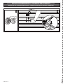 4
4
-
 5
5
-
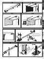 6
6
-
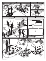 7
7
-
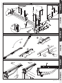 8
8
-
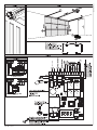 9
9
-
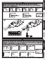 10
10
-
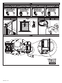 11
11
-
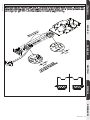 12
12
-
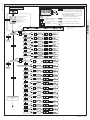 13
13
-
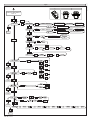 14
14
-
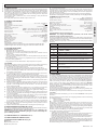 15
15
-
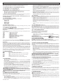 16
16
-
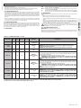 17
17
-
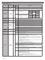 18
18
-
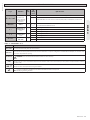 19
19
-
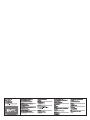 20
20


in altre lingue
- English: BFT Eos 1200 U User manual
Documenti correlati
Altri documenti
-
 Moovo TS4 Manuale del proprietario
-
 Motostar MOTOSTAR Manuale utente
-
Nice Automation Spin11KCE Manuale del proprietario
-
-
 Allmatic XTILUS Manuale utente
-
 DTS ECO 500 Guida d'installazione
-
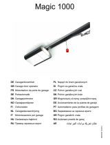 Normstahl Magic 1000 Manuale utente
-
 Sonus Faber Venere 2.5 Manuale del proprietario
-
Heine IC1 Manuale utente


