La pagina si sta caricando...

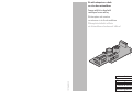
Fig. 1
COMPOSANTS:
1. Interrupteur anti-ouverture
2. Borne pour alimentation de l’interrupteur anti-ouverture
INSTALLATION:
La tension d'alimentation fournie aux bornes de l'interrupteur anti-
ouverture ne doit pas dépasser 24VAC (max 0,5A). Le contact de
l'interrupteur anti-ouverture est considéré normalement fermé ou
normalement ouvert avec le caisson complètement fermé.
Ne pas alimenter le kit avec une tension autre que celle indiquée!
• Débrancher toutes les sources d'alimentation en énergie électrique du caisson et
procéder à l'ouverture de ce dernier.
• Débrancher toutes les connexions réalisées avec la carte électronique standard
placée dans le caisson.
• Remplacer la carte électronique standard par celle équipée de l'interrupteur anti-
ouverture (1) fourni avec le kit, en utilisant si nécessaire les vis fournies.
• Réaliser tous les câblages et connexions prévus avec les composants de la
nouvelle carte électronique.
• Connecter la tension d'alimentation sur la borne identifiée comme J1 sur la carte
électronique.
• Remplacer les vis de fermeture du caisson par celles de type anti-vandalisme
prévues dans le kit au moyen de la clé fournie.
• Fermer le caisson.
FRANCAIS
KOMPONENTEN:
1. Öffnungsschutzschalter
2. Klemme zur Speisung des Öffnungsschutzschalter
INSTALLATION:
Die Versorgungsspannung, mit der die Klemmen des Öffnungsschutzschalters
gespeist werden, darf 24VAC (max. 0,5 A) nicht überschreiten. Der Kontakt
des Öffnungsschutzschalters ist ein Ruhekontakt NCC oder ein
Arbeitskontakt NOC bei völlig geschlossenem Gehäuse.
Das Kit darf nicht mit einer Spannung versorgt werden, die vom
angegebenen Wert abweicht!
• Die Verbindung zu allen Stromversorgungsquellen, die an das Gehäuse angeschlossen
sind, werden unterbrochen und das Gehäuse geöffnet.
• Alle Verbindungen zur elektronischen Standardkarte im Gehäuse werden
unterbrochen.
• Die elektronische Standardkarte wird durch jene ersetzt, die im Bausatz des
Öffnungs-schutzschalters (1) enthalten ist. Bei Bedarf können die mitgelieferten
Schrauben verwendet werden.
• Alle Verdrahtungen und die Anschlüsse der vorgesehenen Komponenten auf der
neuen elektronischen Karte vornehmen.
• Die Versorgungsspannung wird an der Klemme J1 auf der elektronischen Karte
angeschlossen.
• Die Verschlußschrauben für das Gehäuse werden durch die im Bausatz enthaltenen
Schrauben, die speziell gegen Vandalismus sichern, ersetzt und mit dem kleinen,
beiliegenden Schlüssel eingeschraubt.
• Gehäuse schließen.
DEUTSCH
COMPONENTI:
1. Switch antiapertura
2. Morsetto per alimentazione switch antiapertura
INSTALLAZIONE:
La tensione d’alimentazione fornita ai morsetti dello switch
antiapertura non deve superare i 24VAC (max.0,5A). Il contatto dello
switch antiapertura è considerato normalmente chiuso o normalmente
aperto con la custodia completamente chiusa.
Non alimentare il kit con una tensione diversa da quella indicata!
• Scollegare tutte le fonti d’alimentazione collegate con la custodia e procedere alla
sua apertura.
• Scollegare tutte le connessioni realizzate con la scheda elettronica standard presente
nella custodia.
• Sostituire la scheda elettronica standard con quella dotata dello switch antiapertura
(1) fornita nel Kit, utilizzando eventualmente le viti in dotazione.
• Realizzare tutti i cablaggi e i collegamenti previsti con i componenti presenti sulla
nuova scheda elettronica.
• Collegare la tensione di alimentazione nel morsetto indicato con J1 sulla scheda
elettronica.
• Sostituire le viti per la chiusura della custodia con quelle del tipo antivandalismo
previste nel Kit, utilizzando l'apposita chiavetta fornita.
• Chiudere la custodia.
ITALIANO
PARTS:
1. Tamper Switch
2. Terminal for tamper switch power supply
INSTALLATION:
The power supply voltage for the opening-prevention switch terminals
should not exceed 24VAC (max. 0.5A). The contact of the tamper
switch is considered normally open or normally closed with the housing
completely closed.
Never power the kit with a different voltage from the one indicated!
• Disconnect all power sources connected to the housing and then proceed to
open it up.
• Disconnect all the connections made to the standard electronics board present
in the housing.
• Replace the standard electronics board with that fitted with the tamper switch
(1) and supplied with the Kit, using the supplied screws if necessary.
• Complete all the required wiring and connections with the components present
on the new electronics board.
• Connect the power supply to the terminal shown as J1 on the electronics
board.
• Replace the screws closing the housing with the vandal-proof screws supplied
with the Kit, using the special key supplied for this purpose.
• Close the housing.
ENGLISH
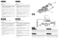
N.C.
N.O.
COM
MAX 24VAC 0.5A
Fig. 2
Il produttore declina ogni responsabilità per eventuali danni derivanti da un uso improprio delle
apparecchiature menzionate in questo manuale. Si riserva inoltre il diritto di modificarne il contenuto senza
preavviso. Ogni cura é stata posta nella raccolta e nella verifica della documentazione contenuta in questo
manuale, tuttavia il produttore non può assumersi alcuna responsabilità derivante dall’utilizzo della stessa.
Lo stesso dicasi per ogni persona o società coinvolta nella creazione e nella produzione di questo manuale.
The manufacturer declines all responsibility for any damage caused by an improper use of the
appliances mentioned in this manual. Furthermore, the manufacturer reserves the right to modify its
contents without any prior notice. The documentation contained in this manual has been collected with
great care, the manufacturer, however, cannot take any liability for its use. The same thing can be
said for any person or company involved in the creation and production of this manual.
Le producteur décline toute responsabilité pour les dommages éventuels dus à une utilisation non appropriée
des appareils mentionnés dans ce manuel. On réserve en outre le droit d’en modifier le contenu sans préavis.
La documentation contenue dans ce manuel a été rassemblée et vérifiée avec le plus grand soin, cependant,le
producteur ne peut pas s’assumer aucune responsabilité dérivante de l’emploi de celle-là. La même chose
vaut pour chaque personne ou société impliquées dans la création et la production de ce manuel.
Der Hersteller lehnt jede Haftung für eventuelle Schäden ab, die aufgrund unsachgemäßer Anwendung der in
diesem Handbuch erwähnten Geräte entstanden ist. Ferner behält er sich das Recht vor, den Inhalt ohne
Vorkündigung abzuändern. Die Dokumentation in diesem Handbuch wurde sorgfältig ausgeführt und
überprüft, dennoch kann der Hersteller keine Haftung für die Verwendung übernehmen. Dasselbe gilt für jede
Person oder Gesellschaft, die bei der Schaffung oder Produktion von diesem Handbuch miteinbezogen ist.
ITALIANO ENGLISH
FRANCAIS DEUTSCH
-
 1
1
-
 2
2


Videotec Tamper switch alarm Manuale utente
- Tipo
- Manuale utente
- Questo manuale è adatto anche per
in altre lingue
Documenti correlati
-
Videotec Alarm tamper switch Manuale utente
-
-
-
-
-
-
-
-