
LD120
Manuale d’uso
LD120-M7
SM5
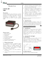
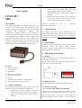
Descrizione
Il presente manuale è stato realizzato per i prodotti
della serie LD120 e SM5. Questo sistema è adatto ad
applicazioni in ambiente industriale e funziona
esclusivamente in abbinamento con i sensori
magnetici della serie SM5 e la banda magnetica
MT50.
Elenco sezioni
1 - Norme di sicurezza
2 - Identificazione
3 - Installazione
4 - Istruzioni di montaggio
5 - Connessioni elettriche
6 - Programmazione
7 - Interfaccia RS-485 (opzione -I4)
8 - Ingombri e dima di foratura
1 - Norme di sicurezza
Per i collegamenti elettrici si consiglia di seguire
scrupolosamente le note applicative di carattere
elettrico riportate sul catalogo generale. Con
particolare riferimento alla direttiva 2014/30/UE
sulla compatibilità elettromagnetica si devono
rispettare le seguenti precauzioni:
installare il sensore il più vicino possibile al
visualizzatore;
utilizzare sempre cavi schermati e possibilmente
"twistati";
evitare di far passare il cavo del sensore vicino a
conduttori che trasportano segnali di potenza
(per es. provenienti dall'inverter);
installare degli appositi filtri EMC (reperibili in
commercio) in ingresso all'alimentazione del
visualizzatore (generalmente è sufficiente un
filtro a "T" o a "P" del tipo L-C oppure in
alternativa un filtro più complesso);
installare il sensore il più lontano possibile
dall'inverter presente sulla macchina. Qualora
non fosse possibile è necessario schermarlo in
maniera efficace dall'inverter stesso.
Rispettare le connessioni riportate nella sezione “5 -
Connessioni elettriche”.
2 - Identificazione
Il dispositivo è identificato mediante il codice e dal
numero di serie stampati sull'etichetta e attraverso i
documenti di trasporto allegati. Per dettagli relativi
alle caratteristiche elettriche dello strumento fare
riferimento al catalogo del prodotto.
3 - Installazione
Il visualizzatore e il sensore devono essere installati
esclusivamente in accordo al loro grado di
protezione e alla temperatura di lavoro previsti e
devono essere protetti da urti accidentali, da
sfregamenti contro altre parti mobili nonché da
soluzioni acide.
4 - Istruzioni di montaggio
4.1 Visualizzatore
Inserire lo strumento nel foro (ca. 68 x 33 mm)
ricavato nel pannello senza le clip di fissaggio.
Agganciare le clip sul lato della custodia del
visualizzatore. Stringere le viti con un cacciavite
finché il visualizzatore è fissato stabilmente.
4.2 Banda magnetica
Si vedano le istruzioni allegate alla banda.
MAN LD120 I_E 1.6.odt 1 www.lika.it
www.lika.biz
2044

LD120
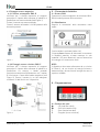
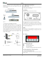
4.3 Fissaggio sensore magnetico
4.3.1 Sensore rettangolare SM5-R
Verificare che il sistema meccanico di supporto
garantisca il rispetto delle tolleranze di planarità e
parallelismo tra sensore e banda (vedi Figura 1).
Evitare il contatto tra sensore e banda.
Fissare il sensore utilizzando 2 viti M3 passanti nelle
due asole presenti.
Figura 1
4.3.2 Fissaggio sensore circolare SM5-C
Verificare che il sistema meccanico di supporto
garantisca il rispetto delle tolleranze di planarità e
parallelismo tra sensore e banda ponendo
particolare attenzione all’allineamento tra il marker
di riferimento e l’asse della banda magnetica (vedi
Figura 2). Fissare il sensore in un foro adeguato
mediante i 2 dadi forniti con il dispositivo.
Figura 2
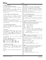
5 - Connessioni elettriche
5.1 Sensore SM5
Connettere il sensore magnetico al connettore Mini-
DIN (circolare) presente sullo strumento.
5.2 Visualizzatore
Eseguire le connessioni della morsettiera come
segue:
L'uscita seriale è opzionale (codice -I4).
L’ingresso Accu consente di alimentare lo strumento
in modalità stand-by a basso consumo. In tale
modalità i LED sono disattivati, mentre l’elettronica
di conteggio e il sensore sono attivi.
NOTA
Il dispositivo deve essere alimentato da un circuito
di Classe 2, da un circuito ad energia limitata a
bassa tensione o da una fonte di energia che non sia
superiore a 30Vdc.
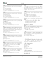
6 - Programmazione
6.1 Funzione dei tasti
: UP (modifica valore)
: Shift left (cambia cifra)
*: Save (memorizza dato)
P: Program (scorre nel menu)
MAN LD120 I_E 1.6.odt 2 www.lika.it
www.lika.biz

LD120
6.2 Funzioni rapide
6.2.1 Reference (o azzeramento)
Premendo il tasto * per ca. 3 secondi si visualizza lo
zero della macchina.
Il valore visualizzato è = rEF + OFS1 + OFSx (dove
OFSx è l'Offset attualmente impostato).
La funzione è attiva solo con il parametro F_rSt
impostato a “on”.
6.2.2 Conteggio incrementale/assoluto
Premendo i tasti P e * il display commuta da
visualizzazione assoluta a incrementale e viceversa.
In modalità incrementale il punto decimale è
lampeggiante.
L’azzeramento (6.2.1) in modalità incrementale non
modifica la quota assoluta dello strumento.
La funzione è attiva solo con parametro F_rEL
impostato a “on”.
6.2.3 Visualizzazione mm/pollici
Premendo il tasto per ca. 3 secondi il display
commuta l'unità di misura visualizzata da mm a
pollici (e viceversa).
6.2.4 Offset
Premendo i tasti P e si accede al primo valore di
Offset (OFS1). Con i tasti e è possibile
modificare il valore di OFS1 e memorizzarlo con il
tasto *. I valori OFS2 e OFS3 sono modificabili solo
tramite set-up.
La funzione è attiva con parametro F_oFS
impostato a “on”.
Premendo il tasto si visualizzano in sequenza i
valori OFS1, OFS2 e OFS3, dove:
OFS1 = quota attuale + OFS1 + rEF
OFS2 = quota attuale + OFS1 + OFS2 + rEF
OFS3 = quota attuale + OFS1 + OFS3 + rEF
6.2.5 Reference (o Preset)
Premendo i tasti P e si accede al valore di
reference rEF. Con i tasti e è possibile
modificare il valore di rEF e memorizzarlo con il
tasto *.
La funzione è attiva con parametro F_rEF impostato
a “on”.
6.3 Setup
Premendo il tasto P per 3 secondi si entra in
programmazione. Sul display appare “SEtUP”.
Premendo il tasto si entra nel Menu 1 (parametri)
Premendo il tasto * si entra nel Menu 2 (RS-485).
Premendo il tasto P si passa dal parametro
all’inserimento del parametro.
Premendo il tasto P per 3 secondi si esce dal set-up.
6.3.1 Parametri di default
I parametri di default (impostazioni di fabbrica) sono
evidenziati in NERETTO.
Lo strumento può essere riportato alle impostazioni
di default premendo il tasto * durante l’accensione.
6.3.2 Elenco parametri MENU 1
rES
[10, 50, 100, 1000, InCH, FrEE] Risoluzione.
Valore in micron della risoluzione lineare.
10 = 10 µm = 0,01 mm
50 = 50 µm = 0,05 mm
100 = 100 µm = 0,1 mm
1000 = 1000 µm = 1 mm
InCH = la quota e i parametri rEF e OFSx sono
gestiti in pollici con 3 cifre decimali (es: 1.000)
FrEE = risoluzione libera (riferita a 0,01 mm di
risoluzione base)
* = salvare, P = prossimo, P x 3 s. = uscire
FrEE
[0.0001, 1.0000] Solo con rES = FrEE.
Es. si vuole visualizzare un angolo da 0° a 90° con
risoluzione 0,1° su una tavola girevole con
circonferenza 785,4 mm. La corsa è pertanto 785,4
mm : 4 = 196.35 mm
FrEE = 900 : 19635 = 0,0458
Valore di default: 0.0001
* = salvare, P = prossimo, P x 3 s. = uscire
dEC
[0, 1, 2, 3] Punto decimale. Solo con rES = FrEE.
Settaggio del punto decimale sul display.
0 = 00000 (nessun decimale)
1 = 0000.0 (1 decimale)
2 = 000.00 (2 decimali)
3 = 00.000 (3 decimali)
* = salvare, P = prossimo, P x 3 s. = uscire
MAN LD120 I_E 1.6.odt 3 www.lika.it
www.lika.biz

LD120
dir
[uP, dn] Direzione di conteggio.
uP = direzione di conteggio standard
dn = direzione di conteggio invertita
* = salvare, P = prossimo, P x 3 s. = uscire
F_rEL
[on, oFF] Abilitazione della funzione di conteggio
incrementale (tramite combinazione di tasti P e *).
on = abilitato (conteggio incrementale)
oFF = disabilitato (conteggio assoluto)
* = salvare, P = prossimo, P x 3 s = uscire
F_rSt
[on, oFF] Abilitazione della funzione di reset tramite
tasto *.
on = funzione abilitata
oFF = funzione disabilitata
Il display visualizza il valore rEF + OFS1 + OFSx
(dove OFSx è l'Offset attualmente impostato).
* = salvare, P = prossimo, P x 3 s. = uscire
F_rEF
[on, oFF] Abilitazione della funzione di reference
(tramite combinazione di tasti P e ).
on = funzione abilitata
oFF = funzione disabilitata
* = salvare, P = prossimo, P x 3 s. = uscire
F_oFS
[on, oFF] Abilitazione della funzione di offset
(tramite combinazione di tasti P e ).
on = funzione abilitata
oFF = funzione disabilitata
* = salvare, P = prossimo, P x 3 s. = uscire
rEF
[-99999, 99999] Valore di reference (o Preset). Può
essere visualizzato premendo il tasto * per 3 sec.
(tiene conto anche dei valori di Offset impostati).
Valore di default: 0
* = salvare, P = prossimo, P x 3 s. = uscire
OFS1
[-99999, 99999] Valore di offset 1 (ad es. spessore
utensile). Se richiamato viene aggiunto alla quota
attuale (vedi 6.2.4.). Valore di default: 0
* = salvare, P = prossimo, P x 3 s. = uscire
OFS2
[-99999, 99999] Valore di offset 2 (vedi anche
parametro OFS1). Valore di default: 0
* = salvare, P = prossimo, P x 3 s. = uscire
OFS3
[-99999, 99999] Valore di offset 3 (vedi anche
parametro OFS1). Valore di default: 0
* = salvare, P = prossimo, P x 3 s. = uscire
NOTA
Per impostare valori negativi posizionarsi sul digit di
segno utilizzando il tasto e modificare il segno
tramite il tasto . Se il segno ”-” lampeggia è
selezionato il valore negativo, altrimenti il valore
positivo. Premere * per salvare.
F_SAP
[on, oFF] Abilitazione funzione di salvataggio allo
spegnimento dell’ultima quota visualizzata.
on = funzione abilitata
oFF = funzione disabilitata
* = salvare, P = prossimo, P x 3 s. = uscire
Al termine del set-up compare la scritta “rESEt”.
Premere P, il display visualizza rEF+OFS1+OFSx.
Premendo il tasto * si effettua l’azzeramento.
Premere 2 volte P per uscire dal set-up.
6.3.3 Elenco parametri MENU 2
Ad xx
[00, 31] Impostazione dell'indirizzo del dispositivo
(necessaria se si dovessero connettere più dispositivi
in rete). Usare il tasto per impostare l’indirizzo.
Valore di default: 0
* = salvare, P = prossimo
H_cnt
Contaore (decimi di ora). Visualizza in decimi di ora
(6 min.) il tempo di funzionamento dello strumento
con alimentazione collegata.
= azzerare contaore, P = uscire
7 - Interfaccia RS-485 (opzione -I4)
Qualora lo strumento fosse stato ordinato completo
di porta seriale RS-485 si possono eseguire i
seguenti comandi e impostazioni.
MAN LD120 I_E 1.6.odt 4 www.lika.it
www.lika.biz

LD120
7.1 Impostazioni porta seriale
Baud rate = 9600
Bit di dati = 8
Parità = nessuna
Bit di stop = 1
Controllo di flusso = Xon/Xoff
7.2 Comandi porta seriale
La struttura dei comandi da inviare via porta seriale
è la seguente:
| A D C M N D = X
dove :
| è il carattere della tastiera PC (in alto a sinistra
sulla tastiera PC)
AD : indirizzo dispositivo (da 00 a 31), 2 caratteri
CMND : comando (si veda più avanti per la lista)
X : eventuale valore da inviare (si veda più avanti)
Nel caso di invio errato il display risponde con lo
stesso comando inviato seguito da “?” e “checksum”
(es. : comando inviato |02azs risposta |02azs?EF)
E possibile inviare i comandi tramite qualsiasi
emulatore di terminale (ad es. Hyperterminal). Il
comando viene inviato alla pressione del tasto Enter
(Carriage Return).
La struttura della risposta del display è la seguente:
ADCMND:SXXXXXCK
dove:
AD : indirizzo dispositivo
CMND : comando
XXXXX : valore
CK : Checksum
La checksum corrisponde al byte meno significativo
della somma di tutti i valori esadecimali dei caratteri
trasmessi.
ESEMPIO
Richiedo la quota al dispositivo con indirizzo 01: |
01TPOS.
La risposta sarà: 01TPOS:+008290F
che corrisponde alla quota 8.29.
La checksum è così calcolata: 30+31+54+50+
4F+53+3A+2B+30+30+38+32+39 = 30F
Il byte meno significativo di 30F è 0F e costituisce la
checksum.
7.2.1 Elenco comandi
(N.B.: di seguito con AD viene indicato in modo
generico l’indirizzo del dispositivo).
Azzeramento indirizzo display
|00RSET
Impostazione a 0 dell’indirizzo di tutti i display
connessi in rete.
Indirizzo display
|00INIT=X
[1, 31] Assegnazione dell’indirizzo X a tutti i display
in rete.
Visualizza indirizzo
|00DADR
Visualizzazione dell'indirizzo del display impostato
fino alla pressione del tasto P.
Cambio indirizzo
|ADRADR=X
[1, 31] Impostazione dell’indirizzo da AD a X.
Risposta: ADRADR:+XCHKS (dove CHKS è la
checksum di 2 caratteri).
Lettura quota attuale
|ADTPOS
Lettura della quota attuale (con risoluzione 0,01mm)
del display con indirizzo AD.
Direzione conteggio
|ADRDIR=X
[0, 1] Impostazione della direzione di conteggio.
X=0 uP = direzione di conteggio standard
X=1 dn = direzione di conteggio invertita
Risposta: ADRDIR:+0000XCHKS
Lettura direzione conteggio
|ADTDIR
Lettura della direzione di conteggio impostata.
X=0uP , X=1dn
Risposta: ADTDIR:+0000XCHKS
Impostazione punto decimale
|ADRDEC=X
[0, 3] Impostazione del punto decimale sul display.
X=0 nessun decimale
X=1 1 decimale (Es. 1,0)
MAN LD120 I_E 1.6.odt 5 www.lika.it
www.lika.biz

LD120
X=2 2 decimali (Es. 1,00)
X=3 3 decimali (Es. 1,000)
Risposta: ADRDEC:+0000XCHKS
ATTENZIONE: il numero di decimali non influenza il
tipo di visualizzazione mm/pollici (si veda sotto il
comando |ADRMMI=0).
Lettura punto decimale
|ADTDEC
Lettura del numero di decimali impostati.
X=0 0, X=1 1, X=2 2, X=3 3
Risposta: ADTDEC:+0000XCHKS
Visualizzazione mm/pollici
|ADRMMI=X
[0, 1] Imposta la visualizzazione in mm o pollici.
X=0 mm
X=1 pollici
Risposta: ADRMMI:+0000XCHKS
Lettura tipo di visualizzazione mm/pollici
|ADTMMI
Lettura del tipo di visualizzazione impostata (mm o
pollici).
X=0 mm, X=1 pollici
Risposta: ADTMMI:+0000XCHKS
Abilitazione conteggio ass./incr.
|ADRRAE=X
[0, 1] Abilitazione della funzione di conteggio
incrementale (tramite combinazione di tasti P e *).
X=0 oFF (funzione disabilitata)
X=1 on (funzione abilitata)
Risposta: ADRRAE:+0000XCHKS
Lettura abilitazione conteggio ass./incr.
|ADTRAE
Lettura dello stato dell'abilitazione del conteggio
assoluto/incrementale.
X=0 oFF, X=1 on
Risposta: ADTRAE:+0000XCHKS
Conteggio assoluto/incrementale
|ADRRLA=X
[0, 1] Impostazione del conteggio incrementale o
assoluto.
X=0 assoluto
X=1 incrementale (relativo)
Risposta: ADRRLA:+0000XCHKS
Lettura conteggio incrementale o assoluto
|ADTRLA
Lettura del tipo di visualizzazione impostata
(incrementale o assoluta).
X=0 assoluta, X=1 incrementale
Risposta: ADTRLA:+0000XCHKS
Abilitazione funzione di Reset
|ADRRSE=X
[0, 1] Abilitazione della funzione di reset tramite
tasto *.
X=0 oFF (funzione disabilitata)
X=1 on (funzione abilitata)
Risposta: ADRRSE:+0000XCHKS
Lettura funzione di reset
|ADTRSE
Lettura dello stato di abilitazione della funzione di
reset.
X=0 oFF, X=1 on
Risposta: ADTRSE:+0000XCHKS
Abilitazione funzione di reference
|ADRRFE=X
[0, 1] Abilitazione della funzione di reference
(tramite combinazione di tasti P e ).
X=0 oFF (funzione disabilitata)
X=1 on (funzione abilitata)
Risposta: ADRRFE:+0000XCHKS
Lettura funzione di reference
|ADTRFE
Lettura dello stato di abilitazione della funzione di
reference
X=0 oFF, X=1 on
Risposta: ADTRFE:+0000XCHKS
Abilitazione funzione di offset
|ADROFE=X
[0, 1] Abilitazione della funzione di offset (tramite
combinazione P e ).
X=0 oFF (funzione disabilitata)
X=1 on (funzione abilitata)
Risposta: ADROFE:+0000XCHKS
MAN LD120 I_E 1.6.odt 6 www.lika.it
www.lika.biz

LD120
Lettura funzione di offset
|ADTOFE
Lettura dello stato di abilitazione della funzione di
offset.
X=0 oFF, X=1 on
Risposta: ADTOFE:+0000XCHKS
Risoluzione sistema
|ADRRES=X
[10, 50, 100, 1000] Valore in micron della risoluzione
lineare.
X=10 10 µm = 0,01 mm
X=50 50 µm = 0,05 mm
X=100 100 µm = 0,1 mm
X=1000 1000 µm = 1 mm
Risposta: ADRRES:+XCHKS
Lettura risoluzione di sistema
|ADTRES
Lettura della risoluzione di sistema impostata (in
micron).
X=10 0,01 mm, X=50 0,05 mm,
X=100 0,1 mm, X=1000 1 mm
Risposta: ADTRES:+XCHKS
Fattore di risoluzione FrEE
|ADRFRE=X
[0.0001, 1.0000] Impostazione del fattore di
risoluzione FrEE.
Risposta: ADRFRE:+XCHKS
Lettura fattore di risoluzione FrEE
|ADTFRE
Lettura del fattore di risoluzione FrEE impostato.
Risposta: ADTFRE:+00X.XXXXCHKS
Valore di reference
|ADRREF=X
[-99999, 99999] Impostazione del valore di
reference (o Preset).
Può essere visualizzato premendo il tasto * per 3
secondi (tiene conto anche dei valori di Offset
impostati). E' espresso con risoluzione 0,01.
Risposta: ADRREF:XCHKS
Lettura valore di reference
|ADTREF
Lettura del valore di reference impostato (in
centesimi di mm).
Risposta: ADTREF:XCHKS
Valore di Offset 1
|ADROF1=X
[-99999, 99999] Impostazione del valore di OFFSET 1
(risoluzione 0,01 mm).
Risposta: ADROF1:XCHKS
Lettura valore di Offset 1
|ADTOF1
Lettura del valore di Offset 1 impostato (risoluzione
0,01 mm).
Risposta: ADTOF1:XCHKS
Valore di Offset 2
|ADROF2=X
[-99999, 99999] Impostazione del valore di OFFSET 2
(risoluzione 0,01 mm).
Risposta: ADROF2:XCHKS
Lettura valore di Offset 2
|ADTOF2
Lettura del valore di Offset 2 impostato (risoluzione
0,01 mm).
Risposta: ADTOF2:XCHKS
Valore di Offset 3
|ADROF3=X
[-99999, 99999] Impostazione del valore di OFFSET 3
(risoluzione 0,01 mm).
Risposta: ADROF3:XCHKS
Lettura valore di Offset 3
|ADTOF3
Lettura del valore di Offset 3 impostato (risoluzione
0,01 mm).
Risposta: ADTOF3:XCHKS
Abilitazione salvataggio ultima quota
|ADRSPE=X
[0, 1] Abilitazione della funzione di salvataggio
dell’ultima quota visualizzata.
X=0 oFF (funzione disabilitata)
X=1 on (funzione abilitata)
Risposta: ADRSPE:+0000000XCHKS
MAN LD120 I_E 1.6.odt 7 www.lika.it
www.lika.biz

LD120
Lettura funzione salvataggio ultima quota
|ADTSPE
Lettura dello stato di abilitazione della funzione di
salvataggio dell'ultima quota.
X=0 oFF, X=1 on
Risposta: ADTSPE:+0000000XCHKS
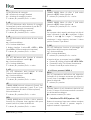
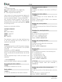
8 - Ingombri e dima di foratura
8.1 Dima di foratura per il visualizzatore
Predisporre un foro rettangolare di 68 x 33 mm.
8.2 Sensore SM5
Si veda il disegno dettagliato sul catalogo del
prodotto
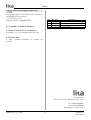
Rev Vers.Man. Descrizione
0 1.0 Prima stampa
- 1.- Aggiornamento manuale
5 1.5 Correzione sezione “6 - Programmazione“
5 1.6 Revisione generale
Lika Electronic
Via S. Lorenzo, 25 • 36010 Carrè (VI) • Italy
Tel. +39 0445 806600
Fax +39 0445 806699
[email protected] • www.lika.biz
MAN LD120 I_E 1.6.odt 8 www.lika.it
www.lika.biz

LD120
User's guide
LD120-M7
SM5
Description
This manual describes the LD120 display and the
sensors of the SM5 series. The purpose of this
system is to show displacement values on industrial
machines and automation systems. The
measurement system includes a LED display, a
magnetic tape and a magnetic sensor. As the sensor
is moved along the magnetic tape, it detects the
displacement which is shown on the display. The
flexibility of the tape allows it to be used for both
linear and angular applications. To be used with
SM5 magnetic sensors and MT50 magnetic tape.
Sections
1 - Safety summary
2 - Identification
3 - Installation
4 - Mounting instructions
5 - Electrical connections
6 - Setup
7 - RS-485 serial interface (-I4 order code)
8 - Dimensional drawing and cut-out
1 - Safety summary
We highly recommend the user's guide to be read
carefully. Follow the installation guidelines:
•measurement system (sensor) should be
installed as close as possible to the display;
•always use shielded and twisted cables if
possible;
•avoid running the sensor cable near high
voltage power cables (e.g. drive cables);
•install EMC filters on sensor power supply if
needed;
•avoid mounting the sensor near capacitive
or inductive noise sources such as relays,
motors, and switching power supplies.
Connect according to the “5 - Electrical
connections” section.
2 - Identification
The display and sensor can be identified by the
label's data (order code, serial number). Information
is listed in the delivery document too. For technical
features of the product please refer to the technical
catalog.
3 - Installation
Install the product according to the protection level
provided. Protect the system against knocks,
friction, solvents, and respect the environmental
characteristics of the device.
4 - Mounting instructions
4.1 Display
Insert the display into the cut-out (approx. 68 x 33
mm) without panel clips.
Install panel clips on the display housing and screw
until the unit is fastened firmly.
4.2 Magnetic tape
See the manual supplied with the magnetic tape.
4.3 Sensor mounting
4.3.1 Sensor type SM5-R (rectangular)
Sensor can be fixed by means of two M3 screws
inserted into the buttonholes. Make sure that the
gap between sensor and tape is met along the
whole measuring length (Figure 1). Avoid contact
MAN LD120 I_E 1.6.odt 9 www.lika.it
www.lika.biz

LD120
between the parts. You can check planarity and
parallelism between sensor and magnetic tape using
a feeler gauge.
Figure 1
4.3.2 Sensor type SM5-C (circular)
The sensor can be fixed in a corresponding
mounting hole by means of the two nuts. Make sure
that the gap between sensor and tape is met along
the whole measuring length (Figure 2). Note the
correct alignment of the marker on the tape. Avoid
contact between the parts. You can check planarity
and parallelism between sensor and magnetic tape
using a feeler gauge.
Figure 2
5 - Electrical connections
5.1 SM5 sensor
Plug in the sensor's Mini-DIN connector (circular) on
the backside of the display.
5.2 Display
Make the clamp connections as follow:
The serial interface is optional (-I4 order code).
The Accu input can supply the device in stand-by
mode with a low consumption. In this way the LEDs
are not active while the electronics can count and
the sensor remains active.
NOTE
This device is to be supplied by a Class 2 Circuit or
Low-Voltage Limited Energy or Energy Source not
exceeding 30Vdc.
6 - Setup
6.1 Function of the keys
: UP (select value)
: Shift left (select digit)
*: Save (save data)
P: Program (programming/change parameter)
6.2 Key combinations / Quick functions
6.2.1 Set datum (Reference)
Press * key for 3 seconds to set the current value to
datum value.
MAN LD120 I_E 1.6.odt 10 www.lika.it
www.lika.biz

LD120
Datum value is = rEF + OFS1 + OFSx (where OFSx
is the Offset value currently set).
This function is enabled only if F_rSt parameter is
set to “on”.
6.2.2 Incremental measurement
Press P and * key simultaneously to switch from
absolute to incremental measurement.
In incremental mode the decimal point flashes.
Zero setting in incremental mode (see 6.2.1) does
not change the absolute value in the background.
6.2.3 Mm/inch display modes
Mm/inch display mode (and vice versa) can be
changed by pressing key for 3 seconds.
6.2.4 Setting the offset value
Press P and keys simultaneously to display Offset
1 value (OFS1). Use and keys to change value
and save with * key. Further Offset values OFS2 and
OFS3 can be changed only in setup menu.
This function is enable only if F_oFS parameter is
set to “on”.
key allows to scroll OFS1, OFS2 and OFS3 values.
OFS1 = current value + OFS1 + rEF
OFS2 = current value + OFS1 + OFS2 + rEF
OFS3 = current value + OFS1 + OFS3 + rEF
6.2.5 Setting the datum
Press P and keys simultaneously to display datum
value rEF. Use and keys to change the value
and save with * key.
This function is enabled only if F_rEF parameter is
set to “on”.
6.3 Setup / Parameter setting
Press P key for 3 seconds to enter setup. “SEtUP” is
displayed.
Press key to enter Menu 1 (parameters)
Press * key to enter Menu 2 (RS-485 serial I/F)
Press P key to access the next Parameter and
Parameter setting.
Press P key for 3 s. to exit setup at any moment.
6.3.1 Default parameters
Default parameter values (factory settings) are
highlighted in BOLD characters. The unit can be
reset to defaults by pressing * key at power-on.
6.3.2 Menu 1: Parameters
rES
[10, 50, 100, 1000, InCH, FrEE] Linear resolution
value expressed in µm (microns).
10 = 10 µm = 0.01 mm
50 = 50 µm = 0.05 mm
100 = 100 µm = 0.1 mm
1000 = 1000 µm = 1 mm
InCH = it sets display mode and measurement unit
to inches (with 3 decimals, e.g. 1.000).
FrEE = it allows to input a free resolution factor,
e.g. for angle display (basis of calculation is
max. resolution 0.01 mm).
* = save, P = next parameter, P for 3 s. = exit
FrEE
[0.0001, 1.0000] Only if rES = FrEE.
E.g. We need to display angles ranging between 0°
and 90° with 0.1° resolution on a rotating table
having a circumference of 785.4 mm. Total work
range is 785.4 mm : 4 = 196.35 mm.
FrEE = 900 : 19635 = 0.0458
Default value = 0.0001
* = save, P = next parameter, P for 3 s. = exit
dEC
[0, 1, 2, 3] Decimal point. Only if rES = FrEE.
It changes the position of the decimal point.
0 = no decimal point
1 = one decimal (e.g. 1.0)
2 = two decimals (e.g. 1.00)
3 = three decimals (e.g. 1.000)
* = save, P = next parameter, P for 3 s. = exit
dir
[uP, dn] Counting direction.
uP = up (standard direction)
dn = down (inverted direction)
* = save, P = next parameter, P for 3 s. = exit
F_rEL
[on, oFF] It enables the incremental measurement
function (by pressing P and * keys).
on = function enabled
oFF = function disabled
* = save, P = next parameter, P for 3 s. = exit
MAN LD120 I_E 1.6.odt 11 www.lika.it
www.lika.biz

LD120
F_rSt
[on, oFF] It enables the reset function (by pressing *
key).
on = function enabled
oFF = function disabled
* = save, P = next parameter, P for 3 s. = exit
F_rEF
[on, oFF] It enables the datum function / Reference
(by pressing * key).
on = function enabled
oFF = function disabled
* = save, P = next parameter, P for 3 s. = exit
F_oFS
[on, oFF] It enables the offset function (by pressing P
and keys).
on = function enabled
oFF = function disabled
* = save, P = next parameter, P for 3 s. = exit
rEF
[-99999, 99999] Datum value, i.e. absolute reference
value for the measuring system. This value is
displayed by pressing * key for 3 seconds (displayed
value includes the set offset values).
Default value = 0
* = save, P = next parameter, P for 3 s. = exit
OFS1
(-99999, 99999) First offset value Offset 1 (e.g. tool
correction). This value is added to the current value
(see 6.2.3).
Default value = 0
* = save, P = next parameter, P for 3 s. = exit
OFS2
[-99999, 99999] Second Offset value Offset 2. This
value is added to the current value and to OFS1.
Default value = 0
* = save, P = next parameter, P for 3 s. = exit
OFS3
[-99999, 99999] Third Offset value Offset 3. This
value is added to the current value and to OFS1.
Default value = 0
* = save, P = next parameter, P for 3 s. = exit
NOTE
To set negative values, select sign digit with key
and change with key. If “-” sign flashes, the
negative value is selected; otherwise positive value
is selected. Press * key to save.
F_SAP
[on, oFF] It saves the last value displayed before
power off.
on = storage of last value enabled
oFF = storage of last value disabled
* = save, P = next parameter, P for 3 s. = exit
When the setup is accomplished the display shows
"rESEt".
Press P key to display rEF + OFS1 + OFSx.
Press * key to reset the display.
Press P key twice to exit setup.
6.3.3 Menu 2: RS-485
Ad xx
[00, 31] It sets the address of the device (only if
ordered with serial interface, -I4 order code).
Default value = 0
* = save, P = next parameter
H_cnt
(1/10 h) Hourmeter. It shows the elapsed time
(display connected to power supply). Resolution is
1/10 hour (6 minutes).
= hourmeter reset, P = exit
7 - RS-485 serial interface (-I4 order code)
If the display is provided with RS-485 serial
interface, the following commands can be used.
7.1 RS-485 parameters
Baud rate = 9600
Data bits = 8
Parity bit = No
Stop bit = 1
Flow control = Xon/Xoff
7.2 Serial commands
Serial commands must have the following structure:
| A D C M N D = X
MAN LD120 I_E 1.6.odt 12 www.lika.it
www.lika.biz

LD120
where:
| : PC keyboard symbol
AD : device address (00 to 31), 2 digit long
CMND : command (see command list)
X : value range (see command list)
Upon receipt of a wrong command the display will
answer with the same command + ? and checksum
(e.g. sent command: |02azs answer |02azs?EF)
Any common terminal program can be used for
communication with LD120 (e.g. Hyperterminal).
Command will be sent after confirmation by ENTER
key (carriage return).
Answers are structured as follow:
ADCMND:SXXXXXCK
where:
AD : device address
CMND : command
XXXXX : value
CK : checksum
The checksum is equal to the least significant byte
of the sum resulting from the hex values of all
characters transmitted.
EXAMPLE
The displayed position is 8.29. The position of device
with address 01 is read by means of the |01TPOS
command.
The answer is: 01TPOS:+008290F
The sum of hex values of all characters is as follows:
30+31+54+50+4F+53+3A+2B+30+30+ 38+ 32+39
= 30F
The least significant byte of 30F is 0F which is the
checksum.
7.2.1 Command list
(below the device address is indicated with AD)
Zero setting the device address
|00RSET
The address of the device is set to 0.
Device address
|00INIT=X
[1, 31] It sets the address of the device to value X.
Displaying the device address
|00DADR
It displays the address of the device until P key is
pressed.
Changing the device address
|ADRADR=X
[1, 31] It changes the current address AD of the
device to X.
Answer: ADRADR:+XCHKS (CHKS is the checksum
and X is the new value).
Reading the current position
|ADTPOS
It reads the current position of device AD (resolution
is 0.01mm).
Changing the counting direction
|ADRDIR=X
[0, 1] It sets the counting direction.
X=0 uP = standard direction
X=1 dn = inverted direction
Answer: ADRDIR:+00000XCHKS
Reading the counting direction
|ADTDIR
It reads the counting direction currently set.
X=0uP , X=1dn
Answer: ADTDIR:+0000XCHKS
Decimal point
|ADRDEC=X
[0, 3] It changes the position of the decimal point.
0 = no decimal point
1 = one decimal (e.g. 1.0)
2 = two decimals (e.g. 1.00)
3 = three decimals (e.g. 1.000)
Answer: ADRDEC:+0000XCHKS
ATTENTION: decimal point setting has no influence
on mm/inch display mode (see command |
ADRMMI=0).
Reading the position of the decimal point
|ADTDEC
It reads the position of the decimal point currently
set.
X=0 0, X=1 1, X=2 2, X=3 3
Answer: ADTDEC:+0000XCHKS
MAN LD120 I_E 1.6.odt 13 www.lika.it
www.lika.biz

LD120
Mm/inch display mode
|ADRMMI=X
[0, 1] It sets mm or inch display mode.
X=0 mm
X=1 inch
Answer: ADRMMI:+0000XCHKS
Reading the mm/inch display mode
|ADTMMI
It reads the display mode currently set.
X=0 mm, X=1 inch
Answer: ADTMMI:+0000XCHKS
Incremental measurement function
[0, 1] It enables the incremental measurement
function (by using P and * key combination).
|ADRRLA=X
X=0 oFF (function disabled)
X=1 on (function enabled)
Answer: ADRRAE:+0000XCHKS
Reading the incremental measurement
|ADTRAE
It reads the enabling status of the incremental
measurement function.
X=0 oFF, X=1 on
Answer: ADTRAE:+0000XCHKS
Incremental measurement
[0, 1] It switches from absolute display mode to
incremental display mode (relative).
|ADRRLA=X
X=0 oFF (disabled = absolute display mode)
X=1 on (enabled = incremental display mode)
Answer: ADRRAE:+0000XCHKS
Read incremental measurement
|ADTRLA
It reads the enabling status of the absolute /
incremental display mode.
X=0 oFF, X=1 on
Answer: ADTRLA:+0000XCHKS
Datum function
|ADRRSE=X
[0, 1] It enables the datum function (by pressing *
key).
X=0 oFF (function disabled)
X=1 on (function enabled)
Answer: ADRRSE:+0000XCHKS
Reading the datum function
|ADTRSE
It reads the enabling status of the datum function.
X=0 oFF, X=1 on
Answer: ADTRSE:+0000XCHKS
Enabling the datum value setting
|ADRRFE=X
[0, 1] It enables the setting of the datum value (by
using P and key combination).
X=0 oFF (function disabled)
X=1 on (function enabled)
Answer: ADRRFE:+0000XCHKS
Reading the datum value setting enabling
|ADTRFE
It reads the enabling status of datum value setting.
X=0 oFF, X=1 on
Answer: ADTRFE:+0000XCHKS
Offset function
|ADROFE=X
[0, 1] It enables the offset function (by using P and
key combination).
X=0 oFF (function disabled)
X=1 on (function enabled)
Answer: ADROFE:+0000XCHKS
Reading the offset function
|ADTOFE
It reads the enabling status of the offset function.
X=0 oFF, X=1 on
Answer: ADTOFE:+0000XCHKS
Resolution
|ADRRES=X
[10, 50, 100, 1000] It sets the linear resolution.
X=10 10 µm = 0,01 mm
X=50 50 µm = 0,05 mm
X=100 100 µm = 0,1 mm
X=1000 1000 µm = 1 mm
Answer: ADRRES:+XCHKS
MAN LD120 I_E 1.6.odt 14 www.lika.it
www.lika.biz

LD120
Reading the resolution
|ADTRES
It reads the resolution value currently set.
X=10 0,01 mm, X=50 0,05 mm,
X=100 0,1 mm, X=1000 1 mm
Answer: ADTRES:+XCHKS
Free resolution factor FrEE
|ADRFRE=X
[0.0001, 1.0000] It sets the free resolution factor
FrEE (see section 6.3.2).
Answer: ADRFRE:+XCHKS
Reading the FrEE factor
|ADTFRE
It reads the factor value FrEE currently set.
Answer: ADTFRE:+X.XXXXCHKS
Setting the datum value
|ADRREF=X
[-99999, 99999] Absolute reference value for the
measurement system. Resolution is 0.01.
Answer: ADRREF:XCHKS
Reading the datum value
|ADTREF
It reads the datum value currently set.
Answer: ADTREF:XCHKS
Setting the Offset 1 value
|ADROF1=X
[-99999, 99999] It sets the Offset 1 (OFS1) value
(resolution 0.01mm).
Answer: ADROF1:XCHKS
Reading the Offset 1 value
|ADTOF1
It reads the Offset 1 value currently set.
Answer: ADTOF1:XCHKS
Setting the Offset 2 value
|ADROF2=X
[-99999, 99999] It sets the Offset 2 (OFS2) value
(resolution 0.01mm).
Answer: ADROF2:XCHKS
Reading the Offset 2 value
|ADTOF2
It reads the Offset 2 value currently set.
Answer: ADTOF2:XCHKS
Setting the Offset 3 value
|ADROF3=X
[-99999, 99999] It sets the Offset 3 (OFS3) value
(resolution 0.01mm).
Answer: ADROF3:XCHKS
Reading the Offset 3 value
|ADTOF3
It reads the Offset 3 value currently set.
Answer: ADTOF3:XCHKS
Save current value function
|ADRSPE=X
[0, 1] It saves the last value displayed before power
off.
X=0 oFF (function disabled)
X=1 on (function enabled)
Answer: ADRSPE:+0000000XCHKS
Reading the save current value function
|ADTSPE
It reads the current enabling status of the save
value function.
X=0 oFF, X=1 on
Answer: ADTSPE:+0000000XCHKS
8 - Dimensional drawing and cut-out
8.1 Display Cut-out
Provide a 68 x 33 mm (w x h) cut-out.
8.2 SM5 sensor
Check details on product catalog.
MAN LD120 I_E 1.6.odt 15 www.lika.it
www.lika.biz

LD120
Rev. Man.Vers. Description
0 1.0 1st issue
1.- SW + Manual update
5 1.5 Section “6 - Setup” corrected
5 1.6 General review
Lika Electronic
Via S. Lorenzo, 25 • 36010 Carrè (VI) • Italy
Tel. +39 0445 806600
Fax +39 0445 806699
[email protected] • www.lika.biz
MAN LD120 I_E 1.6.odt 16 www.lika.it
www.lika.biz
-
 1
1
-
 2
2
-
 3
3
-
 4
4
-
 5
5
-
 6
6
-
 7
7
-
 8
8
-
 9
9
-
 10
10
-
 11
11
-
 12
12
-
 13
13
-
 14
14
-
 15
15
-
 16
16


