
LD111 • LD112
Manuale d’uso
LD111-M7R…
LD112-M7R…
Descrizione
Il presente manuale è stato realizzato per i prodotti
della serie LD11x. Questo sistema di misura e
visualizzazione dispone di alimentazione a batterie
(incluse nella fornitura) ed è stato sviluppato per
funzionare in modo autonomo e indipendente
(senza alimentazione esterna). Lo strumento può
essere abbinato esclusivamente alla banda
magnetica MT25.
Elenco sezioni
1 - Norme di sicurezza
2 - Identificazione
3 - Installazione
4 - Istruzioni di montaggio
5 - Programmazione
6 - Dima di foratura
1 - Norme di sicurezza
Per i collegamenti elettrici si consiglia di seguire
scrupolosamente le note applicative di carattere
elettrico riportate sul catalogo generale. Con
particolare riferimento alla direttiva 2014/30/UE
sulla compatibilità elettromagnetica si devono
rispettare le seguenti precauzioni:
•evitare di far passare il cavo dei segnali del
sensore vicino a conduttori che trasportano
segnali di potenza (per es. provenienti da
inverter);
•installare il dispositivo il più lontano possibile
dalle fonti di disturbi elettromagnetici presenti
sulla macchina. Qualora non fosse possibile è
necessario schermarlo in maniera efficace.
2 - Identificazione
Il dispositivo è identificato mediante il codice e il
numero di serie stampati sull'etichetta e attraverso i
documenti di trasporto allegati. Per dettagli relativi
alle caratteristiche elettriche dell'unità fare
riferimento al datasheet del prodotto.
3 - Installazione
Il visualizzatore e il sensore devono essere installati
esclusivamente in accordo al loro grado di
protezione e la temperatura di lavoro previsti e
devono essere protetti da urti accidentali, da
sfregamenti contro altre parti mobili nonché da
soluzioni acide. Lo strumento è alimentato da due
batterie 1,5V tipo AAA (o AM4 / MICRO / LR03 /
MN2400 / SP/HP16).
4 - Istruzioni di montaggio
4.1 Fissaggio visualizzatore
LD111 Utilizzare due viti M2x14 con distanziale.
LD112 Inserire il display nel foro ricavato nel
pannello senza le staffette di fissaggio;
fissare le staffette sul retro della custodia e
avvitare le due viti M3x30 sulle staffette
fino a portarle in battuta contro il pannello
dove display rimarrà fissato stabilmente.
4.2 Fissaggio banda magnetica
Consultare le istruzioni allegate alla banda
magnetica.
4.3 Fissaggio sensore magnetico
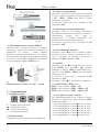
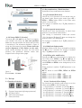
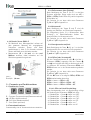
4.3.1 Sensore rettangolare SM25-R
Verificare che il sistema meccanico di supporto
garantisca il rispetto delle tolleranze di planarità e
parallelismo tra sensore e banda (vedi Figura 1).
Evitare il contatto tra sensore e banda.
Fissare il sensore utilizzando 2 viti M3 passanti
nelle due asole presenti.
MAN LD11x I_E_D 1.3.odt 1 www.lika.it
www.lika.biz

LD111 • LD112
Figura 1
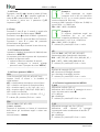
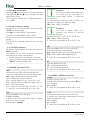
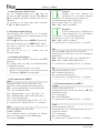
4.3.2 Fissaggio sensore circolare SM25-C
Verificare che il sistema meccanico di supporto
garantisca il rispetto delle tolleranze di planarità e
parallelismo tra sensore e banda ponendo
particolare attenzione all’allineamento tra il marker
di riferimento e l’asse della banda magnetica (Figura
2). Fissare il sensore (Ø = 10 mm) in un supporto
con foro adeguato usando i 2 dadi forniti.
Figura 2
Distanza sensore / anello = 0,1 mm - 1,0 mm
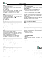
5 - Programmazione
5.1 Funzione dei tasti
P: Program (scorre nel menù)
: UP (modifica valore)
: Shift left (cambia cifra)
*: Save (memorizza dato)
5.2 Funzioni rapide
Di default le funzioni rapide sono tutte disabilitate.
5.2.1 Reset (o azzeramento)
Premendo il tasto * per circa 3 secondi si visualizza
lo zero di macchina. Pertanto il valore visualizzato è
= rEF + OFSt1 + OFStx (dove OFStx è l'Offset
attualmente impostato).
La funzione è attiva solo con il parametro F_rSt
impostato a “yES”.
5.2.2 Conteggio incrementale/assoluto
Premendo i tasti P e * il display commuta da
visualizzazione assoluta a incrementale o viceversa.
L’azzeramento (sezione “5.2.1 Reset (o
azzeramento)”) in modalità incrementale non
modifica la quota assoluta dello strumento.
La funzione è attiva solo con il parametro F_rEL
impostato a “yES”.
5.2.3 Visualizzazione mm/inch
Premendo il tasto per circa 3 secondi il display
commuta l'unità di misura visualizzata da mm a
inch (o viceversa). La funzione è attiva con il
parametro F_mmI impostato a "yES".
5.2.4 Offset
Premendo i tasti P e si accede al primo valore di
Offset (OFSt1). Con i tasti e è possibile
modificare il valore di OFSt1 e memorizzarlo con il
tasto *. I valori OFSt2 e OFSt3 sono modificabili
solo tramite set-up.
La funzione è attiva con il parametro F_oFS
impostato su “yES”.
Premendo il tasto si visualizzano in sequenza i
valori OFSt1, OFSt2 e OFSt3, dove:
OFSt1 = quota attuale + OFSt1 + rEF
OFSt2 = quota attuale + OFSt1 + OFSt2 + rEF
OFSt3 = quota attuale + OFSt1 + OFSt3 + rEF
5.2.4.1 Offset in pollici e frazioni
Con visualizzazione delle quote in pollici e frazioni
di pollici la modifica dei valori di Offset (OFSt)
avviene come segue:
- 1° cifra lampeggiante tasto increm. di 1/64".
- 2° cifra lampeggiante tasto increm. di 1/32".
- 3° cifra lampeggiante tasto increm. di 1/16".
- 4° cifra lampeggiante tasto increm. di 1/8".
- 5° cifra lampeggiante tasto incrementa di 1".
- 6° cifra lampeggiante tasto increm. Di 10".
MAN LD11x I_E_D 1.3.odt 2 www.lika.it
www.lika.biz

LD111 • LD112
5.2.5 Preset
Premendo i tasti P e si accede al valore di Preset
rEF. Con i tasti e è possibile modificare il
valore di rEF e memorizzarlo con il tasto *.
La funzione è attiva con il parametro F_rEF
impostato a “yES”.
5.3 Setup
Premendo il tasto P per 3 secondi si accede alla
programmazione. Sul display appare “SEtUP”.
Premendo il tasto si entra nel Menù 1 (parametri)
Premendo il tasto * si entra nel Menù 2 (Contatore)
Premendo il tasto P si passa dal parametro
all’inserimento del parametro
Premendo il tasto P per 3 secondi si esce dal set-up.
5.3.1 Parametri di default
I parametri di default (impostazioni di fabbrica) sono
evidenziati in NERETTO.
Lo strumento può essere riportato alle impostazioni
di default nel seguente modo:
togliere le batterie e attendere 10 secondi;
inserire nuovamente le batterie tenendo
premuto il tasto * (compare la scritta “dEFPar”).
---------------------------------------------------
5.3.2 Elenco parametri MENU 1
Unit
Unità di misura [dEC, FrEE, dG1, dG2, IdEC, Ifrct]
Imposta l'unità di misura e la modalità di
visualizzazione.
dEC = visualizzazione decimale per misure lineari
FrEE = visualizz. con fattore di conversione libero
dG1 = visualizz. angoli (-..-0,1°..0,0°..+0,1°..+)
dG2 = visualizz. angoli (..359,9°..0,0°..359,9°..0,0°..)
IdEC = pollici con decimali
Ifrct = pollici con frazioni (es. 12.31.64 = 12" 31/64)
* = salvare, P = prossimo, P x 3 sec. = uscire
COn
(Solo con Unit = FrEE, dG1, dG2)
[0.00001, 9.99999]
Consente di impostare un fattore di conversione
della misura per visualizzare angoli o misure non
metriche.
Valore di default: 1.00000
Esempio 1
Si vuole visualizzare un angolo
compreso tra 0° e 90° con risoluzione
di 0,1° su un tavolo girevole avente
una circonferenza di 785,4 mm.
La corsa su 360° è pertanto di 785,4 mm. Su 90,0° la
corsa è 785,4 : 4 = 196.35 mm
COn = 900 : 19635 = 0,045836
Esempio 2
Si vogliono visualizzare angoli con
risoluzione 0,1° su un anello
magnetico di diametro 114,5 mm.
La circonferenza è 114,5 * 3,14 = 359,53 mm
COn = 3600 : 35953 = 0,10013
* = salvare, P = prossimo, P x 3 sec. = uscire
rES
(Solo con Unit = dEC, FrEE, dG1, dG2, IdEC)
Impostazione della risoluzione da visualizzare.
Unit dEC, FrEE, dG1, dG2 = 0.01, 0.05, 0.1, 0.5, 1
Unit IdEC = 0.001, 0.005, 0.01, 0.05, 0.1
* = salvare, P = prossimo, P x 3 sec. = uscire
dIr
Direzione di conteggio [uP, dn]
uP = direzione di conteggio standard
dn = direzione di conteggio invertita
* = salvare, P = prossimo, P x 3 sec. = uscire
---------------------------------------------------
5.3.3 Funzioni supplementari del MENU 1
F_mmI
Abilitazione mm/inch [yES, no]
Abilitazione della funzione di passaggio da mm a
inch e viceversa tramite tasto .
yES = abilitato
no = disabilitato
* = salvare, P = prossimo, P x 3 sec. = uscire
F_rEL
Abilitazione conteggio ass. /incr. [yES, no]
Abilitazione della funzione di conteggio
incrementale tramite combinazione di tasti P e *.
yES = abilitato
no = disabilitato
* = salvare, P = prossimo, P x 3 sec. = uscire
MAN LD11x I_E_D 1.3.odt 3 www.lika.it
www.lika.biz

LD111 • LD112
F_rSt
Abilitazione reset [yES, no]
Abilitazione della funzione di reset tramite tasto *.
yES = abilitato
no = disabilitato
Il display visualizza il valore rEF + OFSt1 + OFStx
(dove OFSt x è l'Offset attualmente impostato).
* = salvare, P = prossimo, P x 3 sec. = uscire
F_rEF
Abilitazione Preset [yES, no]
Abilitazione della modifica del valore di Preset
tramite combinazione di tasti P e .
yES = abilitato
no = disabilitato
* = salvare, P = prossimo, P x 3 sec. = uscire
F_oFS
Abilitazione Offset [yES, no]
Abilitazione della modifica degli offset tramite
combinazione di tasti P e .
yES = abilitato
no = disabilitato
* = salvare, P = prossimo, P x 3 sec. = uscire
rEF
Valore di Preset [-999999, 999999]
Valore Preset (o Reference). Può essere visualizzato
premendo il tasto * per 3 secondi (tiene conto
anche dei valori di Offset impostati).
Parametro accessibile solo con F_rEF abilitato.
* = salvare, P = prossimo, P x 3 sec. = uscire
OFSt1
Offset 1 [-999999, 999999]
Valore di offset (ad es. spessore utensile). Se
richiamato viene aggiunto alla quota attuale (si
veda la sezione “5.2.4 Offset”).
Parametro accessibile solo con F_oFS abilitato.
* = salvare, P = prossimo, P x 3 sec. = uscire
OFSt2
Offset 2 [-999999, 999999]
Secondo valore di offset (si veda anche il parametro
OFSt1).
Parametro accessibile solo con F_oFS abilitato.
* = salvare, P = prossimo, P x 3 sec. = uscire
OFSt3
Offset 3 [-999999, 999999]
Terzo valore di offset (si vedano anche i parametri
OFSt1 e OFSt2).
Parametro accessibile solo con F_oFS abilitato.
* = salvare, P = prossimo, P x 3 sec. = uscire
Al termine del set-up compare la scritta “rESEt”.
Premendo il tasto * si effettua l'azzeramento della
quota e si esce dal set-up (tiene conto di Preset e
Offset impostati).
Premendo il tasto P compare il messaggio “no rSt”,
non si azzera la quota e si esce dal set-up.
---------------------------------------------------
5.3.4. Elenco parametri MENU 2
Ad xx
Funzione non utilizzata.
* = salvare, P = prossimo
H_cntr
Contatore (decimi di ora)
Visualizza il tempo di funzionamento dello
strumento con alimentazione collegata espresso in
decimi di ora (6 minuti).
* = salvare, P = prossimo
6 - Dima di foratura
6.1 LD111
Si veda il disegno dettagliato sul catalogo del
prodotto.
6.2 LD112
Predisporre un foro rettangolare di 68 x 45 mm.
(L x H).
Lika Electronic
Via S. Lorenzo, 25 • 36010 Carrè (VI) • Italy
Tel. +39 0445 806600
Fax +39 0445 806699
[email protected] • www.lika.biz
MAN LD11x I_E_D 1.3.odt 4 www.lika.it
www.lika.biz

LD111 • LD112
User's manual
LD111-M7R…
LD112-M7R…
Description
This manual is designed to describe the LD11x
battery display series. This unit is engineered to
display linear or angular displacements in industrial
machines and automation systems. The
measurement system includes a battery powered
LCD display, a magnetic scale and a magnetic
sensor. As the sensor moves along the magnetic
scale, it detects the displacement value which is
then shown on the display. The flexibility of the
scale allows for use in both linear and angular
applications. To be used with MT25 magnetic scale.
Table of contents
1 - Safety summary
2 - Identification
3 - Installation
4 - Mounting recommendations
5 – Set up
6 - Cut-out
1 - Safety summary
We highly recommend this user's manual to be read
carefully and the installation guidelines followed
properly:
sensor head must be installed as close as
possible to the display;
avoid running the sensor cable near high
voltage power cables (e.g. drive cables);
avoid mounting the sensor head near capacitive
or inductive noise sources such as relays, motors
and switching power supplies.
2 - Identification
The display and the sensor are identified through
the label's data (ordering code, serial number). This
information is listed in the delivery document. For
detailed technical features please refer to the
product datasheet.
3 - Installation
Install the device according to the recommended
protection level. Protect the system against knocks,
friction, solvents and respect the environmental
characteristics of the product. Use two 1.5V
commercial batteries type AAA (or AM4 / MICRO /
LR03 / MN2400 / SP/HP16) for power supply.
4 - Mounting recommendations
4.1 Mounting the display
LD111 Use two M2x14 screws with spacer.
LD112 Insert the display into the panel cut-out
without fixing bars; fasten the fixing bars in
the back of the display and then tighten the
two M3x30 screws in the bars against the
panel frame until the unit is fastened firmly.
4.2 Mounting the magnetic tape
Please refer to the manual supplied with the
magnetic tape.
4.3 Mounting the sensor
4.3.1 Sensor SM25-R (rectangular)
The sensor can be fixed by means of two M3
screws inserted into the buttonholes. Make sure
that the gap between the sensor and the scale is
according the tolerances detailed in Figure 1 along
the total measuring length. Avoid contact between
the parts. You can check planarity and parallelism
between the sensor and the magnetic scale using a
feeler gauge.
MAN LD11x I_E_D 1.3.odt 5 www.lika.it
www.lika.biz

LD111 • LD112
Figure 1
4.3.2 Sensor SM25-C (circular)
The sensor (Ø = 10 mm) can be fixed in a support
with suitable hole using the two nuts provided.
Make sure the gap between the sensor and the scale
is according to the tolerances detailed in Figure 3
along the total measuring length. Please check the
correct alignment of the marker on the scale.
Avoid contact between the parts. You can check
planarity and parallelism between sensor and
magnetic scale using a feeler gauge.
Figure 2
D = 0.1 mm – 1.0 mm
5 – Set up
5.1 Function of the keys
P: Program (programming/change parameter)
: UP (select value)
: Shift links (select digit)
*: Save (save data)
5.2 Key combinations / Quick functions
By default all key combinations are disabled.
5.2.1 Set datum (Reference)
Press * key for 3 seconds to set the actual value to
the datum value. Datum value results from rEF +
OFSt1 + OFStx (where OFStx is the Offset value
which is currently set).
This function is enabled only if F_rSt parameter is
set to “yES”.
5.2.2 Incremental measurement
Press P and * keys simultaneously to switch from
absolute to incremental measurement.
Zero setting in incremental modes (see section
“5.2.1 Set datum (Reference)”) does not change the
absolute value in the background.
The function is enabled only if F_rEL parameter is
set to "yES".
5.2.3 Mm/inch display modes
Mm/inch display mode can be changed by pressing
the key for 3 seconds. The function is enabled
only if F_mmI parameter is set to "yES".
5.2.4 Offset value modification
Press P and keys simultaneously to display the
first Offset value (OFSt1). Use and keys to
change value and save with * key. Further Offset
values OFSt2 and OFSt3 can be changed only in set
up menu.
Offset function is enable if F_oFS parameter is set
to “yES”.
key allows to scroll OFSt1, OFSt2 and OFSt3
values.
OFSt1 = actual value + OFSt1 + rEF
OFSt2 = actual value + OFSt1 + OFSt2 + rEF
OFSt3 = actual value + OFSt1 + OFSt3 + rEF
5.2.4.1 Fractional offset display
The fractional inch display mode allows to set the
offset values (OFSt) in the following way:
- 1st digit blinking increases 1/64” pressing key.
- 2nd digit blinking increases 1/32” pressing key.
- 3rd digit blinking increases 1/16” pressing key.
- 4th digit blinking increases 1/8” pressing key.
- 5th digit blinking increases 1” pressing key.
- 6th digit blinking increases 10” pressing key.
MAN LD11x I_E_D 1.3.odt 6 www.lika.it
www.lika.biz

LD111 • LD112
5.2.5 Datum modification
Press P and keys simultaneously to display datum
value rEF. Use and keys to change value and
save pressing * key.
This function is enabled only if F_rEF parameter is
set to “yES”.
5.3 Set up / Parameter setting
Press P key for 3 seconds to enter the set up mode;
“SEtUP” will be displayed.
Press key to enter MENU 1 (parameters)
Press * key to enter MENU 2 (Hour meter)
Press P key to switch from Parameter to Parameter
setting.
Press P key for 3 seconds to exit the set up at any
moment.
5.3.1 Default parameters
All default values (factory settings) are written in
BOLD characters.
The display can be reset to default parameters
following the procedure here beneath:
•remove the batteries and wait for 10 seconds;
•insert the batteries again while pressing * key
(“dEFPar” message is displayed).
---------------------------------------------------
5.3.2 MENU 1 parameters list
Unit
Measurement unit [dEC, FrEE, dG1, dG2, IdEC, Ifrct]
It sets the measurement unit and the display mode.
dEC = linear measurement display (decimal)
FrEE = display with conversion factor
dG1 = angular display (-..-0.1°..0.0°..+0.1°..+)
dG2 = angular display (..359.9°..0.0°..359.9°..0.0°..)
IdEC = inch display mode
Ifrct = fractional inch mode (eg. 12.31.64 = 12" 31/64)
* = save, P = next parameter, P for 3 sec. = exit
COn
(Only when Unit = FrEE, dG1, dG2)
[0.00001, 9.99999]
It allows to set a free conversion factor to display
non-metric units or angles.
Default value: 1.00000
Example 1
You want to display a 90° angle (from
0° to 90°) with 0,1° resolution in a
round table having a 785.4-mm
circumference.
The measurement length on 360° is 785.4 mm,
therefore it is 785,4 / 4 = 196.35 on 90.0°.
COn = 900 : 19635 = 0.045836
Example 2
You want to display angles on a
magnetic ring having a 114.5-mm
diameter.
The circumference is 114.5 * 3.14 = 359.53 mm
COn = 3600 : 35953 = 0,10013
* = save, P = next parameter, P for 3 sec. = exit
rES
(Only when Unit = dEC, FrEE, dG1, dG2, IdEC)
It sets the resolution to be displayed.
Unit = dEC, FrEE, dG1, dG2 = 0.01, 0.05, 0.1, 0.5, 1
Unit = IdEC = 0.001, 0.005, 0.01, 0.05, 0.1
* = save, P = next parameter, P for 3 sec. = exit
dIr
Counting direction [uP, dn]
uP = up (standard direction)
dn = down (inverted direction)
* = save, P = next parameter, P for 3 sec. = exit
---------------------------------------------------
5.3.3 MENU 1 additional functions
F_mmI
mm/inch function [yES, no]
It enables the mm/inch function pressing key.
yES = enabled
no = disabled
* = save, P = next parameter, P for 3 sec. = exit
F_rEL
Incremental measurement function [yES, no]
It enables the incremental measurement function
(by pressing P and * keys).
yES = enabled
no = disabled
* = save, P = next parameter, P for 3 sec. = exit
MAN LD11x I_E_D 1.3.odt 7 www.lika.it
www.lika.biz

LD111 • LD112
F_rSt
Datum function [yES, no]
It enables the datum function (by pressing * key).
yES = enabled
no = disabled
* = save, P = next parameter, P for 3 sec. = exit
F_rEF
Datum modification function [yES, no]
It enables the reference modification function (by
pressing P and key).
yES = enabled
no = disabled
* = save, P = next parameter, P for 3 sec. = exit
F_oFS
Offset modification function [yES, no]
It enables the offset modification function (by
pressing P and keys).
yES = enabled
no = disabled
* = save, P = next parameter, P for 3 sec. = exit
rEF
Datum value [-999999, 999999]
Absolute reference value for the measuring system.
This value is displayed by pressing * key for 3
seconds (displayed value includes the offset values
which have been set previously).
Parameter is available only if F_rEF is enabled.
* = save, P = next parameter, P for 3 sec. = exit
OFSt1
Offset1 value [-999999, 999999]
First offset value (e.g. tool correction). This value is
added to the current value (see section “5.2.4 Offset
value modification”).
Parameter is available only if F_oFS is enabled.
* = save, P = next parameter, P for 3 sec. = exit
OFSt2
Offset2 value [-999999, 999999]
Second Offset value. This value is added to the
current value and OFSt1.
Parameter is available only if F_oFS is enabled.
* = save, P = next parameter, P for 3 sec. = exit
OFSt3
Offset3 value [-999999, 999999]
Third Offset value. This value is added to the current
value, OFSt1 and OFSt2.
Parameter is available only if F_oFS is enabled.
* = save, P = next parameter, P for 3 sec. = exit
When the set up is accomplished the display shows
the message "rESEt".
Press * to reset the display (according to Preset and
Offset values) and quit the set up.
Press P key to quit the set up without resetting the
display. The message "no rSt" will be displayed.
---------------------------------------------------
5.3.4 Parameter list MENU 2
Ad xx
Function not used
* = save, P = next parameter
H_cntr
Hour meter (1/10 h)
Elapsed time indication (display connected to
battery). Resolution is 1/10 hour (6 minutes).
* = save, P = next parameter
6 - Cut-out
6.1 LD111
Check details on product catalogue.
6.2 LD112
Provide a 68 x 45 mm (w x h) cut-out.
Lika Electronic
Via S. Lorenzo, 25 • 36010 Carrè (VI) • Italy
Tel. +39 0445 806600
Fax +39 0445 806699
[email protected] • www.lika.biz
MAN LD11x I_E_D 1.3.odt 8 www.lika.it
www.lika.biz

LD111 • LD112
Betriebsanleitung
LD111-M7R…
LD112-M7R…
Beschreibung
Diese Betriebsanleitung enthält Informationen und
Anwendungshinweise für die Produkte der Serie
LD11x. Dieses Messsystem ist für allgemeine Weg-
und Winkelmessungen in industriellen Bereichen
geeignet und besteht aus einer batteriebetriebenen
Anzeige, einem Sensor und einem MT25
Magnetband. Der Sensor erfasst die Position
während er über das Magnetband bewegt wird. Die
Position wird auf der Anzeige dargestellt.
Inhalt
1 - Sicherheitshinweise
2 - Identifikation
3 - Inbetriebnahme
4 - Montagehinweise
5 - Parameter und Funktionsebene
6 - Ausbruchsmaße
1 - Sicherheitshinweise
Bitte lesen Sie dieses Dokument vor der
Inbetriebnahme und Montage sorgfältig durch. Des
weiteren sollten beim elektrischen Anschluss
folgende Hinweise, gemäss der EMC-Vorschriften,
beachtet werden.
Signalkabel sollten in möglichst großem Abstand
zu Leitungen, die mit Störungen belastet sind
verlegt werden (z.B. Antriebskabel, Inverterkabel,
usw.).
Das Gerät muss in möglichst großem Abstand zu
Antrieben, Invertern, usw. installiert werden oder
ggf. durch Schirmbleche davon geschützt werden.
2 - Identifikation
Die Produkte können durch den Bestellschlüssel und
die Seriennummer auf dem Typenschild identifiziert
werden. Diese Informationen sind auch in den
Lieferdokumenten enthalten.
3 - Inbetriebnahme
Das gesamte System darf nur gemäß dem
angegebenen Schutzgrad und Arbeitstemperatur
eingesetzt werden. Sensor und Magnetband sollten
zusätzlich gegen Schläge, Reibung und
Lösungsmittel geschützt werden. Die Versorgung
des Geräts erfolgt mittels 2 1,5V Batterien Type
AAA (oder AM4 / MICRO / LR03 / MN2400 /
SP/HP16).
4 - Montagehinweise
4.1 Anzeige
LD111 Das Gerät mit zwei M2x14 Schrauben und
Abstandsstück befestigen.
LD112 Das Gerät wird in eine Schalttafel mit einem
geeigneten Ausbruch eingeführt und über
die Halter festgeschraubt.
4.2 Magnetband
Siehe Betriebsanleitung "Magnetband".
4.3 Montage Magnetsensor
4.3.1 Rechteckiger Sensor SM25-R
Die Mechanik bzw. Montagewinkel müssen auf
dem gesamten Messweg die vorgegebenen
Toleranzen zwischen Sensor und Band
gewährleisten (s. Abb. 1).
Der Kontakt zwischen Sensor und Band muss
verhindert werden.
Magnetsensor mit zwei M3 Schrauben an den
Langlöchern befestigen und ggf. justieren.
MAN LD11x I_E_D 1.3.odt 9 www.lika.it
www.lika.biz

LD111 • LD112
Abb. 1
4.3.2 Runder Sensor SM25-C
Die Mechanik bzw. Montagewinkel müssen auf
dem gesamten Messweg die vorgegebenen
Toleranzen zwischen Sensor und Band
gewährleisten (s. Abb. 2). Ein Kontakt zwischen
Sensor und Band muss verhindert werden.
Magnetsensor (Ø = 10 mm) mit den zwei
Muttern anziehen, dabei besonders auf die
Zählrichtungsmarkierung achten.
Abb. 2
D = 0,1 - 1,0 mm
5 - Parameter und Funktionsebene
5.1 Funktion der Tasten
P: Program (Programmiertaste/Parameterwechsel)
: UP (Wert inkrementieren)
: Shift links (Dekadenwechsel)
*: Save (Daten speichern)
5.2 Tastenkombinationen
Standardmäßig sind die Tastenkombinationen deaktiviert.
5.2.1 Referenzwert (oder Eichung)
Nach Betätigung der Taste * für ca. 3 s wird der
Eichwert angezeigt. Dieser ergibt sich aus rEF +
OFSt1 + OFStx (wobei OFStx der jeweils eingestellte
Offset Wert ist).
Die Funktion ist nur dann aktiv wenn Parameter
F_rSt auf “yES” eingestellt ist.
5.2.2 Kettenmaß
Nach Betätigung der Tasten P und * wird die
Anzeige von Absolute- auf Relativmaß umgestellt.
Die Nullstellung (siehe „5.2.1 Referenzwert (oder
Eichung)“) im Relativmaßmodus ändert den
absoluten Wert im Hintergrund nicht.
Die Funktion ist nur dann aktiv wenn Parameter
F_rEL auf “yES” eingestellt ist.
5.2.3 Anzeigemodus mm/inch
Nach Betätigung der Taste für ca. 3 s. wird der
Anzeigemodus von mm auf Inch (Zoll) gewechselt.
Die Funktion ist nur dann aktiv wenn Parameter
F_mmI auf “yES” eingestellt ist.
5.2.4 Offset (oder Versatzmaß)
Mit der Tastenkombination P und wird der 1.
Offsetwert (OFSt1) angezeigt. Mit den Tasten
und ist es möglich den Wert zu ändern und mit *
zu speichern. Die weiteren Offsetwerte OFSt2 und
OFSt3 können nur in der Parameterebene geändert
werden.
Die Funktion ist nur dann aktiv wenn Parameter
F_oFS auf “yES” eingestellt ist.
Mit der Taste ist es möglich OFSt1, OFSt2 und
OFSt3 nacheinander abzurufen.
OFSt1 = Istwert + OFSt1 + rEF
OFSt2 = Istwert + OFSt1 + OFSt2 + rEF
OFSt3 = Istwert + OFSt1 + OFSt3 + rEF
5.2.4.1 Offset mit Inch Bruchteilung
Beim Anzeigemodus Inch mit Bruchteilung erfolgt
die Änderung der Offsetwerte (OFSt) wie folgt:
- 1. Dekade blinkt Taste erhöht um 1/64".
- 2. Dekade blinkt Taste erhöht um 1/32".
- 3. Dekade blinkt Taste erhöht um 1/16".
- 4. Dekade blinkt Taste erhöht um 1/8".
- 5. Dekade blinkt Taste erhöht um 1".
- 6. Dekade blinkt Taste erhöht um 10".
MAN LD11x I_E_D 1.3.odt 10 www.lika.it
www.lika.biz

LD111 • LD112
5.2.5 Referenzwert (oder Preset)
Mit der Tastenkombination P e wird der
Referenzwert rEF angezeigt. Mit den Tasten und
ist es möglich den Wert zu ändern und mit * zu
speichern.
Die Funktion ist nur dann aktiv wenn Parameter
F_rEF auf “yES” eingestellt ist.
5.3 Parametereingabe (Setup)
Nach Betätigung der Taste P für ca. 3 s wechselt
man von Anzeigemodus zu Parameterebene. Es wird
“SEtUP” angezeigt.
Mit Taste wechselt man zu MENÜ 1 (Parameter).
Mit Taste * wechselt man zu MENÜ 2 (Std-zähler).
Mit Taste P wechselt man vom Parameter zur
Parametereingabe.
Mit Taste P für ca. 3 s verlässt man die
Parameterebene.
5.3.1 Werkseinstellungen
Werkseinstellungen (Default Parameters) sind FETT
gedruckt.
Die Anzeige kann wie folgt auf Werkseinstellung
zurückgesetzt werden:
Batterie entfernen und ca. 10 s. warten
Batterie wieder einfügen und gleichzeitig Taste
* betätigen („dEFPar“ wird angezeigt)
---------------------------------------------------
5.3.2 Parameterliste MENÜ 1
Unit
Messeinheit [dEC, FrEE, dG1, dG2, IdEC, Ifrct]
Messeinheit und Anzeigemodus werden gesetzt.
dEC = metrische Messeinheit (Linearmessungen)
FrEE = frei einstellbarer Faktor
dG1 = Winkelanzeige (-..-0,1°..0,0°..+0,1°..+)
dG2 = Winkelanzeige (..359,9°..0,0°..359,9°..0,0°..)
IdEC = Inch Anzeigemodus
Ifrct = Inch mit Bruchteilung (z.B. 12.31.64 = 12" 31/64)
* = speichern, P = wechseln, P für 3 s. = verlassen
COn
(Nur wenn Unit = FrEE, dG1, dG2)
[0,00001, 9,99999]
Frei einstellbarer Faktor zur Anzeige von Winkeln
oder nicht linearen (metrischen) Messwegen.
Grenzwerte: 1,00000
Beispiel 1
Anzeige eines 90° Winkels mit
Auflösung 0,1° auf einem Drehtisch
mit einem Umfang von785,4 mm.
Der Verfahrweg auf 360° ist 785,4 mm;
daher ist 90,0°, 785,4 : 4 = 196.35 mm
COn = 900 : 19635 = 0,045836
Beispiel 2
Es sollen Winkel mit 0,1° Auflösung auf
einem Magnetring mit Durchmesser
114,5 mm angezeigt werden.
Der Umfang ist 114,5 * 3,14 = 359,53 mm
COn = 3600 : 35953 = 0,10013
* = speichern, P = wechseln, P für 3 s. = verlassen
rES
(Nur wenn Unit = dEC, FrEE, dG1, dG2, IdEC)
Einstellung der Auflösung in der zuvor gewählten
Messeinheit.
Unit = dEC, FrEE, dG1, dG2 = 0.01, 0.05, 0.1, 0.5, 1
Unit = IdEC = 0.001, 0.005, 0.01, 0.05, 0.1
* = speichern, P = wechseln, P für 3 s. = verlassen
dIr
Zählrichtungsumkehr [uP, dn]
uP = Standard Zählrichtung
dn = Invertierte Zählrichtung
* = speichern, P = wechseln, P für 3 s. = verlassen
---------------------------------------------------
5.3.3 Sonderfunktionen im MENÜ 1
F_mmI
mm/inch Funktion [yES, no]
Anzeigemodus kann von mm auf Inch mit Taste
gewechselt werden.
yES = freigegeben
no = nicht freigegeben
* = speichern, P = wechseln, P für 3 s. = verlassen
F_rEL
Kettenmaßfunktion [yES, no]
Kettenmaß kann mit Tastenkombination P und *
aufgerufen werden.
yES = freigegeben
no = nicht freigegeben
* = speichern, P = wechseln, P für 3 s. = verlassen
MAN LD11x I_E_D 1.3.odt 11 www.lika.it
www.lika.biz

LD111 • LD112
F_rSt
Eich Funktion [yES, no]
Anzeige kann mit * Taste geeicht werden.
yES = freigegeben
no = nicht freigegeben
* = speichern, P = wechseln, P für 3 s. = verlassen
F_rEF
Eichwerteingabe [yES, no]
Eichwert kann mit Tastenkombination P und
geändert werden.
yES = freigegeben
no = nicht freigegeben
* = speichern, P = wechseln, P für 3 s. = verlassen
F_oFS
Offsetfunktion [yES, no]
Offsetwerten können mit Tastenkombination P und
geändert werden.
yES = freigegeben
no = nicht freigegeben
* = speichern, P = wechseln, P für 3 s. = verlassen
rEF
Eichwert [-999999, 999999]
Absoluter Bezugspunkt (Referenzwert) des
Messsystems. Dieser wird nach Betätigung der Taste
* für ca. 3 s. angezeigt. Die eingestellten
Offsetwerte werden ebenfalls berücksichtigt. Die
Funktion ist nur dann aktiv wenn Parameter F_rEF
auf “yES” eingestellt ist.
* = speichern, P = wechseln, P für 3 s. = verlassen
OFSt1
Offset 1 [-999999, 999999]
Erster Offsetwert (z.B. Werkzeugkorrektur). Wird
zum Istwert addiert (siehe „5.2.4.1 Offset mit Inch
Bruchteilung“). Die Funktion ist nur dann aktiv wenn
Parameter F_oFS auf “yES” eingestellt ist.
* = speichern, P = wechseln, P für 3 s. = verlassen
OFSt2
Offset 2 [-999999, 999999]
Zweiter Offsetwert. Wird zum Istwert und OFSt1
addiert. Die Funktion ist nur dann aktiv wenn
Parameter F_oFS auf “yES” eingestellt ist.
* = speichern, P = wechseln, P für 3 s. = verlassen
OFSt3
Offset 3 [-999999, 999999]
Dritter Offsetwert. Wird zum Istwert, OFSt1 und
OFSt2 addiert. Die Funktion ist nur dann aktiv wenn
Parameter F_oFS auf “yES” eingestellt ist.
* = speichern, P = wechseln, P für 3 s. = verlassen
Nach Beendung der Parametereingabe wird „rESEt“
angezeigt.
Mit der Taste * wird die Anzeige geeicht und die
Parameterebene verlassen.
Mit der Taste P wird die Parameterebene verlassen
ohne zu eichen und „norSt“ angezeigt.
---------------------------------------------------
5.3.4 Parameterliste MENÜ 2
Ad xx
Funktion nicht benutzt.
* = speichern, P = wechseln
H_cntr
Betriebsstundenzähler (1/10 h)
Zeigt die Betriebsstunden des Geräts mit
angeschlossener Betriebsspannung an. Auflösung ist
1/10 Stunde (6 min.)
* = speichern, P = wechseln
6 - Ausbruchsmaße
6.1 LD111
Genaue Abmessungen und Lage der
Befestigungslöcher dem Katalog bzw. Datenblatt
entnehmen.
6.2 LD112
68 x 45 mm (Breite x Höhe).
Lika Electronic
Via S. Lorenzo, 25 • 36010 Carrè (VI) • Italy
Tel. +39 0445 806600
Fax +39 0445 806699
[email protected] • www.lika.biz
MAN LD11x I_E_D 1.3.odt 12 www.lika.it
www.lika.biz
-
 1
1
-
 2
2
-
 3
3
-
 4
4
-
 5
5
-
 6
6
-
 7
7
-
 8
8
-
 9
9
-
 10
10
-
 11
11
-
 12
12


in altre lingue
- English: Lika LD112 User manual
- Deutsch: Lika LD112 Benutzerhandbuch
Documenti correlati
Altri documenti
-
 CET LBP60 Manuale del proprietario
-
Yamaha AN200 Manuale del proprietario
-
Yamaha PLG150-AN Manuale del proprietario
-
Yamaha S80 Manuale utente
-
-
Yamaha CS6R Manuale del proprietario
-
red lion IMT Instruction Manuale utente
-
-
Toshiba Barcode Reader B-SV4D-GS Manuale utente
-
Snap-On TECHANGLE Manuale utente
