Tyan S2850 Manuale utente
- Categoria
- Schede madri server / workstation
- Tipo
- Manuale utente
Questo manuale è adatto anche per

1
http://www.TYAN.com
Tomcat K8S
///
S2850
Revision 1.01
Copyright © TYAN Computer Corporation, 2003. All rights reserved. No part of this manual may be
reproduced or translated without prior written consent from TYAN Computer Corp.
All registered and unregistered trademarks and company names contained in this manual are
property of their respective owners including, but not limited to the following.
TYAN, Tomcat K8S S2850 are trademarks of TYAN Computer Corporation.
AMD, AMD Opteron, and combinations thereof, are trademarks of Advanced Micro Devices, Inc.
HyperTransport is a licensed trademark of the HyperTransport Technology Consortium.
AMI, AMIBIOS are trademarks of AMI Software Incorporated.
Microsoft, Windows are trademarks of Microsoft Corporation.
SuSE,is a trademark of SuSE AG.
Linux is a trademark of Linus Torvalds.
QLogic, Zircon, and combinations thereof are trademarks of QLogic Corporation.
IBM, PC, AT, PS/2 are trademarks of IBM Corporation.
Winbond is a trademark of Winbond Electronics Corporation.
Broadcom is a trademark of Broadcom Corporation and/or its subsidiaries
ATI and Rage XL are trademarks of ATI Corporation
Portable Document Format (PDF) is a trademark of Adobe Corporation.
Information contained in this document is furnished by TYAN Computer Corporation and has been
reviewed for accuracy and reliability prior to printing. TYAN assumes no liability whatsoever, and
disclaims any express or implied warranty, relating to sale and/or use of TYAN products including
liability or warranties relating to fitness for a particular purpose or merchantability. TYAN retains the
right to make changes to product descriptions and/or specifications at any time, without notice. In
no event will TYAN be held liable for any direct or indirect, incidental or consequential damage,
loss of use, loss of data or other malady resulting from errors or inaccuracies of information
contained in this document.

2
http://www.TYAN.com
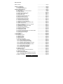
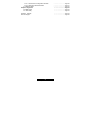
Table of Contents
Before you begin…
Chapter 1: Introduction
1.00 Congratulations!
1.01 Hardware Specifications
Chapter 2: Board Installation
2.00 Block Diagram
2.01 Board Parts, Jumpers and Connectors
2.02 Jumper Settings
2.03 IPMI I
2
C Bus Connector (J13)
2.04 Clear CMOS Jumper (J14)
2.05 USB Header (J22)
2.06 Serial Port Internal Header (J31)
2.07 FAN Connectors (J32~J37)
2.08 Keyboard Lock Jumper (J41)
2.09 External Speaker Header (J42)
2.10 Front Panel Connector (J43)
2.11 Chassis Intrusion Header (J48)
2.12 Gigabit LAN1 LED Header (J51)
2.13 Gigabit or 10/100M LAN2 LED Header (J52)
2.14 Power LED Connector
2.15 Tips on Installing the Motherboard in Chassis
2.16 Installing the Memory
2.17 Installing the Processor and Heatsink
2.18 Thermal Interface Material
2.19 Heatsink Installation Procedures
2.20 Attaching Drive Cables
2.21 Installing Add-In Cards
2.22 PCI Riser Cards Supported on Tomcat K8S S2850
2.23 Connecting External Devices
2.24 Installing the Power Supply
2.25 Finishing up
Chapter 3: BIOS
3.00 BIOS Setup Utility
3.01 BIOS Menu Bar
3.02 BIOS Legend Bar
3.03 BIOS Main Menu
3.04 BIOS Advanced Menu
3.04.1 IDE Configuration Sub-Menu
3.04.2 Floppy Configuration Sub-Menu
3.04.3 Super I/O Configuration Sub-Menu
3.04.4 Hardware Health Configuration Sub-Menu
3.04.5 Event Log Control Sub-Menu
3.04.6 Remote Access Configuration Sub-Menu
3.04.7 USB Configuration Sub-Menu
3.04.8 Onboard Device Sub-Menu
3.04.9 Watchdog Timer Sub-Menu
3.05 BIOS PCI/PnP Menu
3.06 BIOS Boot Menu
3.06.1 Boot Settings Configuration Sub-Menu
3.07 BIOS Security Menu
3.08 BIOS Chipset Setting Menu
3.08.1 North Bridge Chipset Configuration Sub-Menu
3.08.2 South Bridge Chipset Configuration Sub-Menu
3.09 BIOS – Power Menu
………….………………..Page 4
…………………………..Page 5
………….………………..Page 5
……………….…………..Page 5
…………………………..Page 7
……………….…………..Page 8
…………….……………..Page 9
……………..…………..Page 10
………….…………….. Page 10
………………………… Page 11
………………………… Page 11
………………………… Page 12
………………………… Page 12
……….………..…….… Page 13
…………….…..…….… Page 13
………………………… Page 14
………………………… Page 14
………………………… Page 15
………………………… Page 15
………………………… Page 16
………………………… Page 16
………………………… Page 17
………………………… Page 20
………………………… Page 22
………………………… Page 22
………………………… Page 24
……………..…………..Page 25
……………..…………..Page 27
……………..…………..Page 27
……………..…………..Page 28
……………..…………..Page 28
……………..…………..Page 29
……………..…………..Page 29
……………..…………..Page 29
……………..…………..Page 30
……………..…………..Page 30
……………..…………..Page 31
…………………………Page 32
……………….…………Page 33
…………….……………Page 33
…………….……………Page 34
……...……….…………Page 36
…………………………Page 37
…………………………Page 38
…………………………Page 39
…………………………Page 39
…………………………Page 40
…………………………Page 41
……………..…………..Page 42
…………………………Page 43
…………………………Page 44
…………………………Page 45
…………….……………Page 48
…………….……………Page 48

3
http://www.TYAN.com
3.09.1 Advanced ACPI Configuration Sub-Menu
3.09.2 Global Timer Reload Sub-Menu
3.10 BIOS Exit Menu
Chapter 4: Diagnostics
4.00 Beep Codes
4.01 Flash Utility
Appendix I: Glossary
Technical Support
…………….……………Page 50
…………….……………Page 51
…………….……………Page 52
…………………………Page 53
…………………………Page 53
…………………………Page 53
…………………………Page 54
…………………………Page 58

4
http://www.TYAN.com
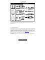
Before you begin…
Check the box contents!
The retail motherboard package should contain the following:
1 x Tomcat K8S S2850 motherboard
1 x CPU retention frame
1 x CPU back plate with insulation and screws
1 x 34-Pin floppy drive cable
1 x Ultra-DMA-133/100/66/33 IDE cable
4 x SATA cable (optional)
2 x SATA Driver Power Adapter (optional)
1 x 25-pin printer cable (optional)
1 x Tomcat K8S S2850 User’s Manual
1 x Tomcat K8S S2850 Quick Reference
1 x TYAN driver CD
1 x Serial ATA driver diskette (optional)
1x I/O shield
If any of these items are missing, please contact your vendor/dealer for replacement before
continuing with the installation process.

5
http://www.TYAN.com
Chapter 1: Introduction
1.00 – Congratulations!
You have purchased one of the most powerful AMD Opteron
TM
processor solutions, the Tomcat
K8S S2850. The Tomcat K8S S2850 features a high bandwidth integrated memory controller for
superior productivity, HyperTransport™ chipset technology to increase overall performance by
removing or reducing I/O bottlenecks, and low profile I/O ports with strategically placed DIMM slots
to allow maximum airflow across the motherboard for efficient system cooling. This platform offers
convenient remote Intelligent Platform Management Interface (IPMI) monitoring through a Server
Management Daughter Card. The Tomcat K8S S2850 also features an ATX form factor, Single or
Dual Gigabit Ethernet port, an onboard ATI 8MB PCI RAGE XL VGA, and an onboard Quad
channel Serial ATA, which provides an advanced and versatile solution for your server needs.
Remember to visit TYAN’s Website at http://www.tyan.com
. There you can find information on all of
TYAN’s products with FAQs, distributors list and BIOS setting explanations.
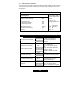
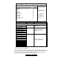
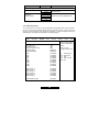
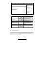
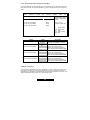
1.01 – Hardware Specifications
Processor
- PGA 940-pin ZIF socket
- Supports one AMD Opteron
TM
processor
- Onboard 3-phase PWM Controller
- Integrated 128-bit DDR Memory Controller
Chipset
- AMD-8111
TM
HyperTransport
TM
I/O Hub
- Winbond W83627HF Super I/O chip
- Winbond W83782D Hardware Monitor
chip
Memory
- 128-bit dual channel memory bus
- Total of four 184-pin 2.5-Volt DDR DIMM
sockets
- Supports up to 8 Gigabytes Registered
DDR *
- Supports ECC type memory modules
- Supports PC1600, PC2100, & PC2700
DDR *
Expansion Slots
- Total of six 32-bit 33MHz (5-Volt) PCI
slots
Integrated Enhanced IDE Controller
- Provides two IDE dual-drive ports for up to
four EIDE devices
- Supports UDMA 33/66/100/133 IDE drives
and ATAPI compliant devices
Integrated I/O
- One floppy connector supports up to
two drives
- Two 9-pin serial ports (one connector
and one header) and One 25-pin
parallel port header (connector is
optional)
- PS/2 mouse and keyboard
connectors
- Four USB v1.1 ports (2 stacked rear
connectors; 2 USB headers)
BIOS
- AMI
®
BIOS 8.0 on 4Mbit LPC Flash
ROM
- Supports ACPI 1.0b
- 48-bit LBA Support
- Supports PXE via Ethernet
- Supports USB device boot
- Watchdog timer
System Management
- Total of six 3-pin fan headers
- All fan headers with tachometer
monitoring
- One 2-pin Chassis Intrusion header
- Temperature, voltage and fan
monitoring

6
http://www.TYAN.com
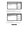
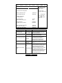
Integrated LAN Controllers
- Dual Broadcom
®
BCM5705 GbE/100/10
LAN controllers
- Two RJ-45 LAN connectors with LEDs
Integrated PCI Graphics
- ATI
Rage
TM
XL PCI graphics controller
- 8MB Frame Buffer of video memory
Integrated Serial ATA Controller (MFG
Option)
- Silicon Image SiI3114 SATA controller
- Supports four-channel SATA RAID (RAID
0,1, 0+1)
- Total of four 7-pin SATA connectors
- Supports SATA 1.0 Specification
* Not validated at the time of print, subject to
change.
Form Factor
- ATX footprint (12” x 8.2”)
- 6-layer board
- ATX12V universal power connectors
- Serial (one) and VGA (one)
connectors
- Stacked USB 1.1 (two) connectors
- Stacked PS/2 keyboard and mouse
connectors
- Two RJ-45 LAN connectors with
LEDs
Regulatory
- FCC Class B (Declaration of
Conformity)
- European Community CE
(Declaration of Conformity)
Software Specifications
OS (Operating System) Support
Microsoft Windows NT 4 Service Pack 6A
Microsoft Windows 2000
Microsoft Windows XP
Microsoft Windows Server 2003
SuSE Server 8.0 for AMD-64
Red Hat 8.0, 9.0
Other distributions of Linux pending validation
TYAN reserves the right to add support or discontinue support for any OS with or
without notice.

7
http://www.TYAN.com
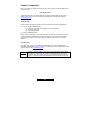
Chapter 2: Board Installation
Installation
You are now ready to install your motherboard. The mounting-hole pattern of the Tomcat K8S
S2850 matches the ATX specification. Before continuing with installation, confirm that your chassis
supports an ATX motherboard.
How to install our products right…. the first time!
The first thing you should do is read this user’s manual. It contains important information that will
make configuration and setup much easier. Here are some precautions you should take when
installing your motherboard:
(1) Ground yourself properly before removing your motherboard from the antistatic bag.
Unplug the power from your computer power supply and then touch a safely grounded
object to release static charge (i.e. power supply case). For the safest conditions, Tyan
recommends wearing a static safety wrist strap.
(2) Hold the motherboard by its edges and do not touch the bottom of the board, or flex the
board in any way.
(3) Avoid touching the motherboard components, IC chips, connectors, memory modules,
and leads.
(4) Place the motherboard on a grounded antistatic surface or on the antistatic bag that the
board was shipped in.
(5) Inspect the board for damage.
The following pages include details on how to install your motherboard into your chassis, as well as
installing the processor, memory, disk drives and cables.
NOTE DO NOT APPLY POWER TO THE BOARD IF IT HAS BEEN DAMAGED

8
http://www.TYAN.com
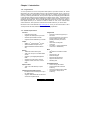
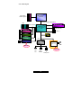
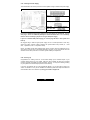
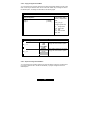
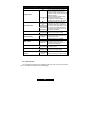
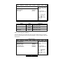
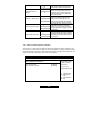
2.00 – Block Diagram
AMD-8111
TM
HyperTransport
TM
IO HUB
AMD Opteron
TM
Processor
200-333MHz
144bit Reg DDR
8x8 H
yp
erTrans
p
ort
TM
@
400MT/s
PCI
32-bit, 33MHz
LPC
Super I/O
SATA SiI3114
BCM5705
BCM5705
/BCM4401
ATI Rage XL
EIDE (ATA 133)
USB 1.1
FDD
Port
PS/2
KB&MS
Printer
&
Serial ports
LPC
Winbond 83782D
Optional
BMC
(IPMI 1.5)
SMB
IPM
ICM
BIOS
Optional

9
http://www.TYAN.com
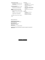
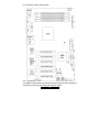
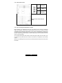
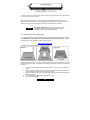
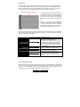
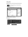
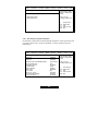
2.01 – Board Parts, Jumpers and Connectors
Note: A □ depicts pin #1
This diagram is representative of the latest board revision available at the time of publishing.
The board you receive may not look exactly like the above diagram.

10
http://www.TYAN.com
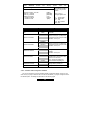
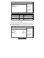
2.02 – Jumper Settings
Jumper Function Settings
J13 IPMI I2C Bus Connector See Section 2.03
J14 Clear CMOS Jumper See Section 2.04
J22 USB Header See Section 2.05
J31 Serial Port Internal Header See Section 2.06
J32 Chassis Fan Connector See Section 2.07
J33 CPU Fan Connector See Section 2.07
J34 Chassis Fan Connector See Section 2.07
J35 Chassis Fan Connector See Section 2.07
J36 Chassis Fan Connector See Section 2.07
J37 Chassis Fan Connector See Section 2.07
J41 Keyboard Lock Connector See Section 2.08
J42 External Speaker Header See Section 2.09
J43 Front Panel Connector See Section 2.10
J48 Chassis Intrusion Header See Section 2.11
J51 LAN 1 LED Header See Section 2.12
J52 LAN 2 LED Header See Section 2.13
J57 Power LED Connector See Section 2.14
Jumper Legend
OPEN - Jumper OFF Without jumper cover
CLOSED - Jumper ON With jumper cover
To indicate the location of pin-1
To indicate the location of pin-1
2.03 – IPMI I
2
C Bus Connector (J13)
Pin_4 : NC
Pin_3 : SMBUSC_0
Pin_2 : GND
Pin_1 : SMBUSD_0
Use this connector to connect external IPMI
I
2
C Bus devices

11
http://www.TYAN.com
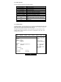
2.04 – Clear CMOS Jumper (J14)
Pin_3
Pin_1
Default
Pin_3
Pin_1
Clear
You can reset the CMOS settings by using this
jumper if you have forgotten your system/setup
password or need to clear system BIOS setting.
- Power off system and disconnect both
power connectors from the
motherboard
- Use jumper cap to close Pin_2 and Pin_3
for several seconds to Clear CMOS
- Put jumper cap back to Pin_1 and Pin_2
(default setting)
Reconnect power & power on system
2.05 – USB Header (J22)
Signal Description
Pin
#
Pin
#
Signal Description
VCC 1 2 VCC
USB Channel_1 Data - 3 4 USB Channel_2 Data -
USB Channel_1 Data
+
5 6
USB Channel_2 Data
+
GND 7 8 GND
NC 9 10 GND

12
http://www.TYAN.com
2.06 – Serial Port Internal Header (J31)
Signal Description Pin # Pin #
Signal
Description
DCD (Data Carrier
Detect)
1 2
DSR (Data-Set-
Ready)
RXD (Receive-
Data)
3 4
RTS (Request-to-
Send)
TXD (Transfer-
Data)
5 6
CTS (Clear-to-
Send)
DTR (Data-
Terminal-Ready)
7 8
RI (Ring-
Indicator)
GND
9 10
NC
2.07 – FAN Connectors (J32~J37)
#
FAN
Description
Function
Amp Rated
(Maximum)
J33 CPU FAN1
RPM
Read
1.0A
J34
Chassis
FAN2
RPM
Read
1.0A
J35
Chassis
FAN3
RPM
Read
1.0A
J32
Chassis
FAN4
RPM
Read
1.0A
J36
Chassis
FAN5
RPM
Read
1.0A
J37
Chassis
FAN6
RPM
Read
1.0A

13
http://www.TYAN.com
2.08 – Keyboard Lock Jumper (J41)
OPEN (Default)
To enable PS/2 keyboard
CLOSED
To disable PS/2 keyboard
2.09 – External Speaker Header (J42)
Pin_1 : Speaker +
Pin_2 : Buzzer +
Pin_3 : Speaker/
Buzzer -
Pin_1
Pin_4
Pin_4 : Speaker -
Close Pin-2and Pin-3 (Default)
Enable onboard buzzer
Open Pin-1 ~ Pin-4
Disable onboard buzzer and can
connect to chassis 1x4 speaker

14
http://www.TYAN.com
2.10 – Front Panel Connector (J43)
Functi
on
PIN
#
PIN
#
Function
HDD
LED+
1 2
PWR
LED+
HDD
LED-
3 4 PWR LED-
Reset
Button -
5 6
PWR
Button+
Reset
Button+
7 8
PWP
Button -
NC 9 10
Sleep
Button+
NC 11 12
Sleep
Button-
NC 13 14 NC
NC 15 16 NC
Chassis
Intru +
17 18
Chassis
Intru -
2. 11 – Chassis Intrusion Header (J48)
1 2
Pin_1 INTRUDER_L
Pin_2 GND
The Chassis Intrusion Header
provides chassis intrusion-monitoring
function.
Note: For use with chassis that
support this feature.

15
http://www.TYAN.com
2. 12 – Gigabit LAN1 LED Header (J51)
Pin_4 : Green -
Pin_3 : Green +
Pin_2 : Yellow -
Pin_1
Pin_1 : Yellow +
Green LED solid= 10Mb link
Green LED flashing= 10Mb activity
Yellow LED solid= 100Mb link
Yellow LED flashing= 100Mb activity
Both LED Solid= Gigabit link
Both LED flashing= Gigabit activity
2. 13 – Gigabit or 10/100M LAN2 LED Header (J52)
Pin_4 : Green -
Pin_3 : Green +
Pin_2 : Yellow -
Pin_1
Pin_1 : Yellow +
Gigabit LAN:
The same as J51 (LAN1).
10/100M LAN (optional):
Green LED solid= 10Mb link
Green LED flashing= 10Mb activity
Yellow LED solid= 100Mb link
Yellow LED flashing= 100Mb activity

16
http://www.TYAN.com
2.14 – Power LED Connector
PIN_1 PWR LED (+)
PIN_2 NC
Pin_1
Pin_3
PIN_3 PWR LED (-)
Note: For some chassis with 3-pin
cable.
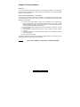
2.15 – Tips on Installing the Motherboard in Chassis
Before installing your motherboard, make sure your chassis has the necessary motherboard
support studs installed. These studs are usually metal and are gold in color. Usually, the chassis
manufacturer will pre-install the support studs. If you’re unsure of stud placement, simply lay the
motherboard inside the chassis and align the screw holes of the motherboard to the studs inside
the case. If there are any studs missing, you will know right away since the motherboard will not be
able to be securely installed.
Some chassis include plastic studs instead of metal. Although the plastic studs are usable, Tyan
recommends using metal studs with screws that will fasten the motherboard more securely
in place.
Below is a chart detailing what the most common motherboard studs look like and how they should
be installed.

17
http://www.TYAN.com
TIP: Use metal studs if possible, as they hold the motherboard into place more securely than
plastic standoffs.
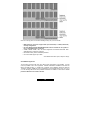
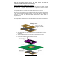
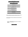
2.16 – Installing the Memory
Before attempting to install any memory, make sure that the memory you have is compatible with
the motherboard as well as the processor. For example, while PC1600 DDR modules are
compatible with all DDR based motherboards, they will not work if you are required to run the
motherboard and processor buses at 133MHz. For this, PC2100 DDR modules are required.
Critically important is whether you’re using the recommended memory for the current board you
have. For this information, please check Tyan’s web site at: www.tyan.com
The following diagram shows the common types of RAM modules you may encounter depending
on your board:

18
http://www.TYAN.com
Here are a few key points to note before installing memory into your Tomcat K8S:
• AMD Opteron
TM
processors support 64bit (non-interleaved) or 128bit (interleaved)
memory configurations
• At least ONE Registered DDR SDRAM module must be installed for the system to
turn on and POST (power on self test)
• 128MB, 256MB, 512MB, 1GB, and 2GB* Registered PC2700/PC2100/PC1600 DDR
SDRAM memory modules are supported
• All installed memory will be automatically detected
• The Tomcat K8S supports up to 8GB. *
* Not validated at the time of print, subject to change.
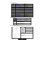
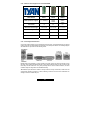
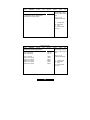
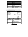
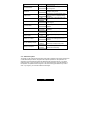
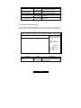
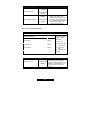
Valid DIMM Configurations
The processor supports 64-bit mode and 128-bit mode configurations of the DIMMs. In 64-bit
mode, only DIMMs 1 and 3 can be populated. Possible combinations of DIMMs in 64-bit mode are
listed in the table as below. In 128-bit mode, a minimum of two DIMMs is required to create the
128-bit bus; therefore, DIMMs can only be populated in even numbered pairs in slots 1 & 2, and 3
& 4. The following table shows some possible combinations of DIMMs for 128-bit mode. Not all
possible combinations are listed in the table.

19
http://www.TYAN.com
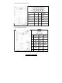
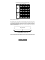
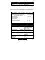
This chart outlines the rules for populating memory
(Note: X = Do not populate)
DIMM Slot DIMM1 DIMM2 DIMM3 DIMM4
X X 256 X
256 X 256 X
X X 512 X
512 X 512 X
X X 1024 X
1024 X 1024 X
X X 2048 X
1024 X 2048 X
2048 X 2048 X
X X 4096 X
64-bit
Mode
(MB)
4096 X 4096 X
X X 256 256
256 256 256 256
X X 512 512
512 512 512 512
X X 1024 1024
1024 1024 1024 1024
X X 2048 2048
2048 2048 2048 2048
X X 4096 4096
128-bit
Mode
(MB)
4096 4096 4096 4096
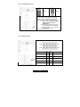
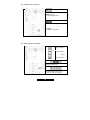
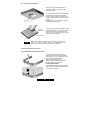
Memory Installation Procedure
When installing memory modules, make sure the modules align properly with the memory socket.
There should be keys (small indents) on your memory modules that fit according to the keys in the
memory socket. DDR modules and sockets have only one key, which is slightly near the center of
the module/socket. SDRAM modules (also referred to as PC100 or PC133) and their sockets have
two keys and will not insert into DDR DIMM sockets. The method of installing memory modules is
detailed in the following diagrams.
Once the memory modules are firmly seated in the socket, two clamps on either side will close and
secure the module into the socket. Sometimes you may need to close the clamps manually.

20
http://www.TYAN.com
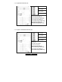
To remove the memory module, simply push the clamps outwards until the memory module pops
up. Then simply remove the module.
TIP: When installing memory, a module may require a considerable amount of force to seat
properly, although this is very rare. To avoid bending and damaging your motherboard, place it on
its anti-static bag and onto a flat surface, and then proceed with memory installation.
NOTE
YOU MUST ALWAYS unplug the power connector to the
motherboard before performing system hardware changes, to
avoid damaging the board or expansion device.
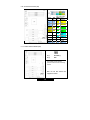
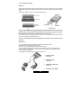
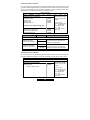
2.17 – Installing the Processor and Heatsink
Your Tomcat K8S S2850 supports the latest 64-bit processor technologies from AMD. However,
only AMD Opteron
TM
processor are certified and supported with this motherboard. Check the
following page on TYAN’s website for latest processor support:
http://www.Tyan.com
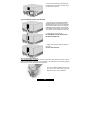
The following diagrams will detail how to install your processor:
The processors you choose to use may not look exactly like the one pictured above, nor will the
socket look exactly the same. The diagram is provided as a visual guide to help you install socket
processors.
1. Lift the lever on the socket until it is approximately 130
o
or as far back as possible to the
socket.
2. Align the processor with the socket. There are keys underneath the processor just like on
memory modules to ensure that they insert the correct way.
3. Seat the processor firmly into the socket by gently pressing down until the processor sits
flush with the socket.
4. Place the socket lever back down until it snaps into place.
5. Your processor is installed.
La pagina sta caricando ...
La pagina sta caricando ...
La pagina sta caricando ...
La pagina sta caricando ...
La pagina sta caricando ...
La pagina sta caricando ...
La pagina sta caricando ...
La pagina sta caricando ...
La pagina sta caricando ...
La pagina sta caricando ...
La pagina sta caricando ...
La pagina sta caricando ...
La pagina sta caricando ...
La pagina sta caricando ...
La pagina sta caricando ...
La pagina sta caricando ...
La pagina sta caricando ...
La pagina sta caricando ...
La pagina sta caricando ...
La pagina sta caricando ...
La pagina sta caricando ...
La pagina sta caricando ...
La pagina sta caricando ...
La pagina sta caricando ...
La pagina sta caricando ...
La pagina sta caricando ...
La pagina sta caricando ...
La pagina sta caricando ...
La pagina sta caricando ...
La pagina sta caricando ...
La pagina sta caricando ...
La pagina sta caricando ...
La pagina sta caricando ...
La pagina sta caricando ...
La pagina sta caricando ...
La pagina sta caricando ...
La pagina sta caricando ...
La pagina sta caricando ...
La pagina sta caricando ...
-
 1
1
-
 2
2
-
 3
3
-
 4
4
-
 5
5
-
 6
6
-
 7
7
-
 8
8
-
 9
9
-
 10
10
-
 11
11
-
 12
12
-
 13
13
-
 14
14
-
 15
15
-
 16
16
-
 17
17
-
 18
18
-
 19
19
-
 20
20
-
 21
21
-
 22
22
-
 23
23
-
 24
24
-
 25
25
-
 26
26
-
 27
27
-
 28
28
-
 29
29
-
 30
30
-
 31
31
-
 32
32
-
 33
33
-
 34
34
-
 35
35
-
 36
36
-
 37
37
-
 38
38
-
 39
39
-
 40
40
-
 41
41
-
 42
42
-
 43
43
-
 44
44
-
 45
45
-
 46
46
-
 47
47
-
 48
48
-
 49
49
-
 50
50
-
 51
51
-
 52
52
-
 53
53
-
 54
54
-
 55
55
-
 56
56
-
 57
57
-
 58
58
-
 59
59


Tyan S2850 Manuale utente
- Categoria
- Schede madri server / workstation
- Tipo
- Manuale utente
- Questo manuale è adatto anche per
in altre lingue
- English: Tyan S2850 User manual