Istruzioni ed avvertenze per l’installazione e l’uso
Instructions and warnings for installation and use
Instructions et avertissements pour l’installation et l’usage
Anleitungen und Hinweise zu Installation und Einsatz
Instrucciones y advertencias para su instalación y uso
Instruções e advertências para a instalação e utilização
Instrukcje i zalecenia dotyczące instalacji i użytkowania
Motoriduttore per cancelli a battente
Gear motor for hinged gates
Motoréducteur pour portails à battants
Motorreductor para cancelas batientes
Antriebe für Drehtore
Motorredutores para portões de batente
Motoreduktor do bram skrzydłowych
RÉVO+

2
125 260
310
MIN 50
575
MAX 740450
KG
IT - Peso massimo dell’ anta del cancello
EN - Maximum weight of the gate door
FR - Poids maximum du battant du portail
ES - Peso máximo de la puerta de la cancela
DE - Maximales Gewicht des Torügels
PT - Peso máximo do painel do portão
PL - Waga maksymalna skrzydła bramy
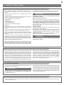
IT
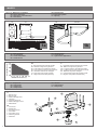
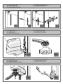
1 - Braccio curvo
2 - Braccio dritto
3 - Staa di ssaggio anta
4 - Finecorsa
5 - Coperchio necorsa
6 - Staa di ssaggio a muro
7 - Motoriduttore
EN
1 - Curved arm
2 - Straight arm
3 - Door xing bracket
4 - Limit switch
5 - Limit switch cover
6 - Wall xing bracket
7 - Gearmotor
1a 1b
m
IT - Lunghezza massima dell’ anta del cancello
EN - Maximum length of the gate door
FR - Longueur maximum du battant du portail
ES - Longitud máxima de la puerta de la cancela
DE - Maximale Länge des Torügels
PT - Comprimento máximo do painel do portão
PL - Długość maksymalna skrzydła bramy
MAXIMUM DOOR LENGTH (m)
MAX DOOR WEIGHT (kg)
IMAGES
Fig. 1 IT - Dimensioni d’ ingombro DE - Abmessungen
EN - Space dimensions PT - Dimensões globais
FR - Dimensions d’encombrement PL - Wymiary
ES - Dimensiones
Fig. 2 IT - Limiti di impiego DE - Einsatzgrenzen
EN - Use limitations PT - Limites de uso
FR - Limites d’utilisation PL - Ograniczenia użytkowania
ES - Límites de uso
Fig. 3 IT - Componenti DE - Bauteile
EN - Components PT - Componentes
FR - Composants PL - Komponenty
ES - Componentes
1
2
3
4
4
5
6
7

3
200
190
180
170
160
150
140
130
120
110
100
90
80
70
60
50
40
30
20
10
0
100 110 120 130 140 150 160 170 180 190 200 210 220 230 240 250 260 270 280 290 300
A
C
90/95°
95/100° 100/105°
105/110°
110/115°
115/120°
120°
1 1
22
3 3
4
5
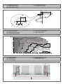
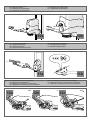
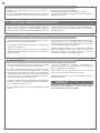
Fig. 4 IT - Rappresentazione quote DE - Darstellung der Werte
EN - Quotes representation PT - Quotas de representação
FR - Représentation hauteurs PL - Przedstawienie wartości
ES - Representación cuotas
Fig. 5 IT - Graco angolo di apertura DE - Zeichnung zum Önungswinke
EN - Opening angle graph PT - Gráco ângulo de abertura
FR - Graphique angle d’ouverture PL - Wykres kąta otwarcia
ES - Gráco ángulo de apertura
Fig. 6 IT - Installazione tipica DE - Typische Installation
EN - Typical Installation PT - Gráco ângulo de abertura
FR - Installation type PL - Wykres kąta otwarcia
ES - Instalación típica
C
A E
C
A

4
7a
8a 8b
9a 9b
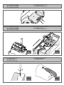
Fig. 7 IT - Posizionamento del motoriduttore DE - Positionierung des Antriebs
EN - Positioning the motor PT - Posicionamento do motorredutor
FR - Positionnement moteur PL - Położenie motoreduktora
ES - Colocación del motorreductor
Fig. 8 IT - Fissaggio motoriduttore DE - Befestigung des Antriebs
EN - Fixing the motor PT - Fixação do motorredutor
FR - Fixation moteur PL - Mocowanie motoreduktora
ES - Fijación del motorreductor
Fig. 9 IT - Fissaggio stae DE - Befestigung des Torbeschlags
EN - Fixing the leaf bracket PT - Fixação da placa do portão
FR - Fixation patte portail PL - Mocowanie obejmy bramy
ES - Fijación del estribo en la puerta
8 mm
A
7b 7c 7d

5
10a
11a
12a
10b
11b
12b 12c
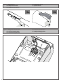
Fig. 10 IT - Sblocco del motoriduttore DE - Entriegeln des Getriebemotors
EN - Gearmotor release PT - Desbloqueio do motorredutor
FR - Déblocage du motoréducteur PL - Odblokowanie motoreduktora
ES - Desbloqueo del motorreductor
Fig. 11 IT - Fissaggio staa cancello DE - Anbringung des Torbeschlags
EN - Fixing the leaf bracket PT - Fixação da placa do portão
FR - Fixation patte portail PL - Mocowanie obejmy bramy
ES - Fijación del estribo en la puerta
Fig. 12 IT - Regolazione dei necorsa meccanici DE - Einstellung der mechanischen Endanschläge
EN - Mechanical stop adjustment PT - Regulação dos blocos dos ns de curso mecânicos
FR - Réglage bloc de n de course mécaniques PL - Regulacja mechanicznych wyłączników krańcowych
ES - Regulación de los nales de carrera mecánicos
MAX
LOCKUNLOCK

6
Fig. 15 IT - Posizione coperchio DE - Position des Deckels
EN - Positioning the cover PT - Posição da tampa
FR - Position couvercle PL - Położenie pokrywy
ES - Posición de la cubierta
Fig. 13 IT - Montaggio tappo necorsa DE - Montage der Endschalterkappe
EN - Limit switch cap assembly PT - Montagem da tampa do m de curso
FR - Montage bouchon n de course PL - Montaż zatyczki wyłącznika krańcowego
ES - Montaje tapón n de recorrido
Fig. 14 IT - Connessioni elettriche DE - Elektrische Anschlüsse
EN - Electrical connections PT - Conexões eléctricas
FR - Connexions électriques PL - Połączenia elektryczne
ES - Conexiones eléctricas
12
1 cm
14a 14b

7
Fig. 16 IT - Connessioni e cablaggi DE - Anschlüsse und Verdrahtung
EN - Connections and cables PT - Ligações e cabos
FR - Connexions et câblages PL - Podłączenia i okablowanie
ES - Conexiones y cableados
Fig. 17 IT - Connessioni e cablaggi DE - Anschlüsse und Verdrahtung
EN - Connections and cables PT - Ligações e cabos
FR - Connexions et câblages PL - Podłączenia i okablowanie
ES - Conexiones y cableados
17a 17b
Fig. 18 IT - Rimozione mascherina DE - Entfernen der Abdeckung
EN - Removing the mask PT - Retirada da cobertura
FR - Retrait masque PL - Demontaż osłony
ES- Extracción de la tapa
18a 18b

8
Fig. 19 IT - Sostituzione led DE - Auswechseln der Led
EN - Replacement of the leds PT - Substituição led
FR - Remplacement des DEL PL - Wymiana diod led
ES - Sustitución de las luces led
Fig. 20 IT - Collegamento secondo motore DE - Anschluss des Zweitmotors
EN - Second motor connections PT - Ligação do segundo motor
FR - Connexion deuxième moteur PL - Podłączenie drugiego silnika
ES - Conexión del segundo motor
COM
LED
M-
M+
1
2
3
19a 19b

9
IT
1
2
3
4
5
6
Avvertenze per la sicurezza
2.1
2.2
4.1
4.2
4.3
4.4
4.5
5.1
5.2
Introduzione al prodotto
Descrizione del prodotto
Modello e caratteristiche tecniche
Veriche preliminari
Installazione del prodotto
Installazione
Regolazione del necorsa meccanico in
apertura
Connessioni elettriche
Connessioni meccaniche ed elettroniche
del secondo motore
Sostituzione led
Collaudo e messa in servizio
Collaudo
Messa in servizio
Dichiarazione CE di conformità
pag. 10
pag. 12
pag. 12
pag. 12
pag. 12
pag. 13
pag. 13
pag. 13
pag. 13
pag. 13
pag. 14
pag. 14
pag. 14
pag. 14
pag. 51
Immagini pag. 2
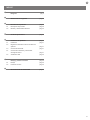
INDICE

IT
10
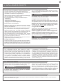
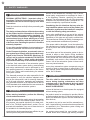
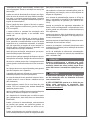
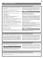
1 - AVVERTENZE PER LA SICUREZZA
ATTENZIONE !
ISTRUZIONI ORIGINALI – importanti istruzioni di
sicurezza. Seguire tutte le istruzioni perchè una
scorretta installazione può portare a lesioni gravi!
Conservare queste istruzioni.Leggere attentamente
le istruzioni prima di eseguire l’installazione.
La progettazione e la fabbricazione dei dispositivi
che compongono il prodotto e le informazioni
contenute nel presente manuale rispettano le
normative vigenti sulla sicurezza. Ciò nonostante
un’installazione e una programmazione errata
possono causare gravi ferite alle persone che
eseguono il lavoro e a quelle che useranno
l’impianto. Per questo motivo, durante
l’installazione, è importante seguire attentamente
tutte le istruzioni riportate in questo manuale.
Non procedere con l’installazione se si hanno dubbi di
qualunque natura e richiedere eventuali chiarimenti al
Servizio Assistenza Key Automation.
Per la legislazione Europea la realizzazione di una
porta automatica o un cancello automatico deve
rispettare le norme previste dalla Direttiva 2006/42/
CE (Direttiva Macchine) e in particolare, le norme
EN 12453; EN 12635 e EN 13241-1, che consentono
di dichiarare la conformità dell’automazione.
In considerazione di ciò, il collegamento denitivo
dell’automatismo alla rete elettrica, il collaudo
dell’impianto, la sua messa in servizio e la
manutenzione periodica devono essere eseguiti
da personale qualicato ed esperto, rispettando le
istruzioni riportate nel riquadro “Collaudo e messa in
servizio dell’automazione”.
Inoltre, egli dovrà farsi carico di stabilire anche le prove
previste in funzione dei rischi presenti e dovrà vericare
il rispetto di quanto previsto da leggi, normative e
regolamenti: in particolare, il rispetto di tutti i requisiti
della norma EN 12453 che stabilisce i metodi di prova
per la verica degli automatismi per porte e cancelli.
ATTENZIONE !
Prima di iniziare l’installazione, eettuare le
seguenti analisi e veriche:
vericare che i singoli dispositivi destinati
all’automazione siano adatti all’impianto da realizzare.
Al riguardo, controllare con particolare attenzione i dati
riportati nel capitolo “Caratteristiche tecniche”. Non
eettuare l’installazione se anche uno solo di questi
dispositivi non è adatto all’uso;
vericare se i dispositivi acquistati sono sucienti a
garantire la sicurezza dell’impianto e la sua funzionalità;
eseguire l’analisi dei rischi che deve comprendere
anche l’elenco dei requisiti essenziali di sicurezza
riportati nell’Allegato I della Direttiva Macchine,
indicando le soluzioni adottate. L’analisi dei rischi è
uno dei documenti che costituiscono il fascicolo tecnico
dell’automazione. Questo dev’essere compilato da un
installatore professionista.
Considerando le situazioni di rischio che possono
vericarsi durante le fasi di installazione e di uso
del prodotto è necessario installare l’automazione
osservando le seguenti avvertenze:
non eseguire modiche su nessuna parte
dell’automatismo se non quelle previste nel presente
manuale. Operazioni di questo tipo possono solo
causare malfunzionamenti. Il costruttore declina ogni
responsabilità per danni derivanti da prodotti modicati
arbitrariamente;
evitare che le parti dei componenti dell’automazione
possano venire immerse in acqua o in altre sostanze
liquide. Durante l’installazione evitare che i liquidi
possano penetrare all’interno dei dispositivi presenti;
se il cavo di alimentazione risulta danneggiato esso
deve essere sostituito dal costruttore o dal suo servizio
di assistenza tecnica o comunque da una persona con
qualica similare in modo da prevenire ogni rischio;
se sostanze liquide penetrano all’interno delle
parti dei componenti dell’automazione, scollegare
immediatamente l’alimentazione elettrica e rivolgersi
al Servizio Assistenza Key Automation. L’utilizzo
dell’automazione in tali condizioni può causare
situazioni di pericolo;
non mettere i vari componenti dell’automazione
vicino a fonti di calore né esporli a amme libere.
Tali azioni possono danneggiarli ed essere causa di
malfunzionamenti, incendio o situazioni di pericolo;
ATTENZIONE !
L’unità deve essere scollegata dalla fonte di alimentazione
durante la pulizia, la manutenzione e la sostituzione
di componenti. Se il dispositivo di sconnessione non
è a vista, apporre un cartello con la seguente dicitura:
“MANUTENZIONE IN CORSO”.
tutti i dispositivi devono essere collegati ad una linea
di alimentazione elettrica dotata di messa a terra di
sicurezza;
il prodotto non può essere considerato un ecace
sistema di protezione contro l’intrusione. Se desiderate
proteggervi ecacemente, è necessario integrare
l’automazione con altri dispositivi;
il prodotto può essere utilizzato esclusivamente

11
IT
esempio irrigatori o idropulitrici;
nel caso in cui il sistema di automazione superasse i
20 Kg di peso, è necessario movimentarlo utilizzando
dispositivi per il sollevamento in sicurezza (IEC 60335-
2-103: 2015);
prevedere le opportune protezioni di sicurezza, al ne
di evitare lo schiacciamento e l'intrappolamento tra la
parte guidata in movimento ed eventuali elementi ssi
circostanti;
assicurarsi che ogni dispositivo di protezione o
sicurezza, oltre allo sblocco manuale, funzionino in
modo corretto;
posizionare in luogo ben visibile la targa identicativa
dell'automazione;
conservare i manuali e i fascicoli tecnici di tutti i dispositivi
utilizzati per la realizzazione dell'automazione;
al termine dell'installazione dell'automazione si
raccomanda di consegnare i manuali relativi alle
avvertenze destinate all'utente nale;
ATTENZIONE !
Esaminare periodicamente l’impianto per vericare
la presenza di sbilanciamenti e segni di usura
meccanica, danneggiamento di cavi, molle, parti di
sostegno.
Non utilizzare se è necessaria riparazione o
regolazione.
ATTENZIONE !
Il materiale dell’imballaggio di tutti i componenti
dell’automazione deve essere smaltito nel pieno
rispetto della normativa presente a livello locale.
Key Automation si riserva il diritto di modicare
le presenti istruzioni qualora necessario, queste
e/o versione superiore si possono trovare sul sito
www.keyautomation.it
dopo che è stata eettuata la “messa in servizio”
dell’automazione, come previsto nel paragrafo
“Collaudo e messa in servizio dell’automazione”;
prevedere nella rete di alimentazione dell’impianto
un dispositivo di disconnessione con una distanza di
apertura dei contatti che consenta la disconnessione
completa nelle condizioni dettate dalla categoria di
sovratensione III;
per la connessione di tubi rigidi e essibili o passacavi
utilizzare raccordi conformi al grado di protezione IP55
o superiore;
l’impianto elettrico a monte dell’automazione deve
rispondere alle vigenti normative ed essere eseguito
a regola d’arte;
l’apparecchio può essere utilizzato da bambini di
età non inferiore a 8 anni e da persone con ridotte
capacità siche, sensoriali o mentali, o prive di
esperienza o della necessaria consapevolezza,
purché sotto sorveglianza oppure dopo che le stesse
abbiano ricevuto istruzioni relative all’uso sicuro
dell’apparecchio e alla comprensione dei pericoli ad
esso inerenti;
prima di avviare l’automazione assicurarsi che le
persone non siano nelle immediate vicinanze;
prima di procedere a qualsiasi operazione di pulizia
e manutenzione dell’automazione eseguire la
disconnessione dalla rete elettrica;
fare particolare attenzione per evitare lo schiacciamento
tra la parte guidata ed eventuali elementi ssi
circostanti;
i bambini devono essere sorvegliati per sincerarsi che
non giochino con l’apparecchio;
l’apparecchio non può essere utilizzato con una porta
guidata che incorpora una porta pedonale;
installare qualsiasi comando sso a un’altezza minima
di 1,5m e in vista sulla porta, ma lontano da parti in
movimento;
dopo l’installazione, vericare che nessun punto della
porta sporga sul marciapiede o sulla via pubblica;
qualora il dispositivo sia dotato di pulsante separato
di arresto, tale pulsante dovrà essere chiaramente
identicabile;
installare l'automazione esclusivamente su cancelli
operanti su superci pianeggianti, ovvero che non
siano installati in salita o discesa;
installare esclusivamente su cancelli sucientemente
robusti e idonei a reggere i carichi sviluppati
dall'automazione stessa;
non sottoporre l'automazione a getti d'acqua diretti, ad

IT
12
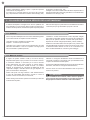
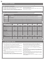
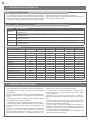
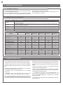
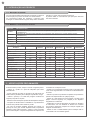
CODICE DESCRIZIONE
REP2024 Motoriduttore 24 Vdc per anta singola a battente con lunghezza max 2,3 m o peso 250 Kg, 230 Vac (1x900PO24 incluso)
REP2024M Motoriduttore 24 Vdc Master per doppia anta a battente con lunghezza max 2,3 m o peso 250 Kg, 230 Vac
(2x900PO24 inclusi)
REP2024S Motoriduttore 24 Vdc Slave per ante a battente con lunghezza max 2,3 m o peso 250 Kg, 230 Vac, senza centrale
di comando
REP2224 Motoriduttore 24 Vdc per ante a battente con lunghezza max 2,3 m o peso 250 Kg, 230 Vac
REP2224S Motoriduttore 24 Vdc per ante a battente con lunghezza max 2,3 m o peso 250 Kg, 230 Vac, senza centrale di comando
I motoriduttori RÉVO+ sono destinati all’installazione in impianti di
automazione per cancelli con ante battenti.
I motoriduttori RÉVO+ sono progettati e costruiti per il montaggio
su ante battenti nei limiti di peso riportati nella tabella delle
speciche tecniche.
É vietato l’utilizzo dei motoriduttori per applicazioni dierenti da
quelle sopra indicate.
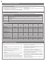
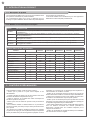
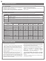
DATI TECNICI
MODELLI REP2024 REP2024M REP2024S REP2224 REP2224S
SPECIFICHE TECNICHE
Coppia Nm 120 120 120 120 120
Ciclo di lavoro cicli/ora 60 60 60 60 60
Tempo di apertura a 90° sec 14-20 14-20 14-20 14-20 14-20
Centrale di comando 14A 14A - CT20224 -
Alimentazione Vac 230 230 - 230 -
Alimentazione Vdc - - 24 - 24
Assorbimento motore A 0,6 0,6 2 0,6 2
Potenza motore W 115 115 50 115 50
Luce integrata si si si - -
Grado di protezione IP 44 44 44 44 44
Dimensioni (L - P - H) mm 125 - 260 - 310
Peso Kg 10,5 10,5 8 10,5 8
Temperatura di esercizio °C -20°+55° -20°+55° -20°+55° -20°+55° -20°+55°
Peso massimo anta Kg 250 250 250 250 250
Prima di installare il prodotto vericare e controllare i seguenti
punti:
- Controllare che il cancello o la porta siano adatti ad essere
automatizzati
- Il peso e la dimensione del cancello o della porta devono rientrare
nei limiti d’impiego massimi consentiti indicati in Fig.2
- Controllare la presenza e la solidità degli arresti meccanici di
sicurezza del cancello o della porta
- Vericare che la zona di ssaggio del prodotto non sia soggetta
ad allagamenti
- Condizioni di elevata acidità o salinità o la vicinanza a fonti di
calore potrebbero causare malfunzionamenti del prodotto
- In caso di condizioni climatiche estreme (per esempio in presenza
di neve, ghiaccio, elevata escursione termica, temperature elevate)
gli attriti potrebbero aumentare e quindi la forza necessaria per la
movimentazione e lo spunto iniziale potrebbe essere superiori a
quella necessaria in condizioni normali.
- Controllare che la movimentazione manuale del cancello o della
porta sia uida e priva di zone di maggiore attrito e non vi sia
rischio di deragliamento dello stesso
- Controllare che il cancello o la porta siano in equilibrio e
rimangano quindi fermi se lasciati in qualsiasi posizione
- Vericare che la linea elettrica a cui sarà collegato il prodotto sia
provvista di opportuna messa a terra di sicurezza e protetta da un
dispositivo magnetotermico e dierenziale
- Prevedere nella rete di alimentazione dell'impianto un dispositivo
di disconnessione con una distanza di apertura dei contatti che
consenta la disconnessione completa nelle condizioni dettate dalla
categoria di sovratensione III.
- Vericare che tutto il materiale utilizzato per l’installazione sia
conforme alle normative vigenti
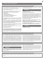
2 - INTRODUZIONE AL PRODOTTO
3 - VERIFICHE PRELIMINARI
2.1 - Descrizione del prodotto
2.2 - Modello e caratteristiche tecniche

13
IT
Con il motoriduttore sbloccato, aprire l’anta no al punto di
apertura desiderato. Prendere il blocchetto necorsa, posizionarlo
sul braccio nella corona dentata assicurandosi che i dentini del
necorsa siano perfettamente ingranati con la corona dentata e
che il bloccaggio sia stabile, quindi ssarlo con la vite M6x25TCE
in uno dei fori di bloccaggio (Fig. 12a). È possibile eseguire
una regolazione accurata della posizione di apertura dell'anta
allentando la vite del necorsa e spostando il blocchetto nelle
posizioni consentite dai dentini della corona (Fig. 12b). Nel caso
si necessitasse di una posizione intermedia tra due dentini è
suciente ruotare di 180° il blocchetto necorsa rispetto alla vite
di ssaggio. Una volta terminata la regolazione, serrare la vite
(Fig. 12c). Utilizzare la stessa procedura per regolare il necorsa
in chiusura utilizzando il secondo blocchetto. Una volta conclusa
la regolazione di entrambi i necorsa, riposizionare il coperchio
sul braccio applicando una leggera pressione nchè non avviene
uno scatto e il coperchio di protezione rimane ssato al braccio in
posizione stabile (Fig. 13).
Prima di procedere con l’installazione, vericare l’integrità del prodotto
e che tutti i componenti siano presenti nella confezione (Fig. 3).
Vericare inoltre che la zona di ssaggio del motoriduttore sia
compatibile con le dimensioni di ingombro (Fig. 1).
Vericare l’angolo di apertura consentito in base ai punti di ssaggio
delle stae tramite Fig. 4 e il graco di Fig. 5.
In Fig.6 è rappresentato un esempio di installazione tipica:
- Fotocellule (1)
- Motoriduttori (2)
- Colonnine per fotocellule (3)
- Selettore a chiave o tastiera digitale (4)
- Lampeggiante con antenna integrata (5)
Posizionamento del motoriduttore
Misurare la quota C (Fig. 4) = distanza tra il fulcro di rotazione
dell’anta e la supercie del pilastro dove verrà ssata la staa
posteriore del motoriduttore.
Portare manualmente l’anta no all’apertura desiderata (massimo
120°): determinando il valore dell’angolo massimo di apertura.
Segnare nel graco di Fig. 5 la quota C trovata e tracciare da
questo punto una linea orizzontale no ad intersecare l’area che
comprende il valore dell’angolo misurato precedentemente.
Nei punti d’intersezione tra la linea orizzontale e l’area, tracciare
delle linee verticali determinando i valori utilizzabili per la quota A
(g. 4). Quindi, scegliere un valore di A.
Riportare sul pilastro il valore trovato della quota A e tracciare in
corrispondenza una linea verticale (Fig. 7a).
Fissaggio staa pilastro
Tracciare sul pilastro una linea orizzontale alla stessa altezza in
cui verrà a trovarsi la staa di ssaggio anta del cancello (Fig. 7b).
Posizionare la staa di ssaggio a muro in modo che l’interno del
bordo inferiore sia più basso di 8mm rispetto la linea orizzontale di
Svitare le viti del coperchio superiore (Fig. 14a). Alzare la parte
posteriore di circa 1 cm, quindi slarlo in avanti (Fig. 14b).
Le luci del coperchio sono collegate tramite due li, scollegare
il morsetto oppure appoggiare il coperchio con attenzione
sottosopra sul lato esterno (Fig. 15).
Nel caso di installazione del secondo motore seguire i punti precedentamente indicati per il ssaggio meccanico, per la connessione
elettrica fare riferimento alla Fig. 20.
Inserire il cavo di alimentazione (Fig. 16). Svitare le viti del
supporto della centrale di comando (Fig. 17a). Collegare i li
del cavo di alimentazione alla morsettiera secondo lo schema
elettrico (Fig. 17b). Procedere con gli altri collegamenti seguendo
le istruzioni della centrale di comando presente sul motore e al
termine ssare nuovamente la centrale al supporto. Rimettere il
coperchio superiore e avvitare le 2 viti che ssano il coperchio.
4 - INSTALLAZIONE DEL PRODOTTO
4.1 - Installazione
4.2 - Regolazione dei necorsa meccanici
4.3 - Connessioni elettriche
4.4 - Connessioni meccaniche ed elettriche del secondo motore
Un ssaggio fuori asse può provocare malfunzionamenti
all’automazione e provocarne la rottura.
Fissaggio braccio motore (braccio dritto)
Sganciare il coperchio necorsa dal braccio dritto tirandolo (Fig.
8b). Collegare il braccio al motoriduttore facendo combaciare
i corrispondenti proli a croce. Unire i due elementi con la vite
M8x25TCE e la rondella in dotazione serrando con forza (Fig. 9a).
Fissare il braccio curvo al braccio dritto mediante il perno e l'anello
di arresto (Fig. 9b). Fissare la staa di ssaggio anta al braccio
curvo tramite il perno ma senza anello di arresto (Fig. 9b)
Fissaggio staa cancello
Portare l’anta del cancello nella posizione di massima chiusura.
Sbloccare il motoriduttore (Fig. 10a e Fig. 10b)
Estendere completamente i bracci, avvicinare il braccio curvo
all’anta e appoggiare su quest’ultima la staa di ssaggio all'anta.
Tenendo con una mano la staa a contatto con l’anta, provare a
eettuare una apertura e una chiusura completa (Fig. 11a).
Fissare la staa cancello all’anta con viti adeguate (non fornite)
(Fig. 11b) e ssare il perno con l’anello di arresto.
Un ssaggio non in bolla può provocare malfunzionamenti
all’automazione e provocarne la rottura.
ATTENZIONE !
ATTENZIONE !
ATTENZIONE !
Fig. 7b e ssarla utilizzando viti e rondelle adeguate (non fornite).
Fissare il motoriduttore alla staa pilastro con viti, rondelle e dadi
in dotazione (Fig. 8a).

IT
14
Togliere l’alimentazione elettrica. Aprire il coperchio superiore
come indicato nel paragrafo 4.3.
Con l’aiuto di un cacciavite svitare la vite interna del coperchio
(Fig. 18a). Estrarre la mascherina e slare la striscia led (Fig. 18b).
Scollegare il connettore (Fig. 19a).
Collegare i nuovi led e inserirli nella mascherina. Riposizionare la
mascherina inserendo prima il lato guarnizione e successivamente
ssandola con la vite (Fig. 19b).
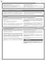
5 - COLLAUDO E MESSA IN SERVIZIO DELL’AUTOMAZIONE
Il collaudo dell impianto va eseguito da un tecnico qualicato che
deve eettuare le prove richieste dalla normativa di riferimento in
funzione dei rischi presenti, vericando il rispetto di quanto previsto
Tutti i componenti dell’impianto devono essere collaudati seguendo
le procedure indicate nei rispettivi manuali di istruzioni;
controllare che siano rispettate le indicazioni del
Capitolo 1 - Avvertenze per la sicurezza;
controllare che la porta si possa muovere liberamente una volta
sbloccata l’automazione e che sia in equilibrio e rimanga quindi
ferma se lasciata in qualsiasi posizione;
A seguito del positivo collaudo di tutti (e non solo di alcuni) i
dispositivi dell’impianto si può procedere con la messa in servizio;
è necessario realizzare e conservare per 10 anni il fascicolo
tecnico dell’impianto che dovrà contenere lo schema elettrico,
il disegno o foto dell’impianto, l’analisi dei rischi e le soluzioni
adottate, la dichiarazione di conformità del fabbricante di tutti
i dispositivi collegati, il manuale istruzioni di ogni dispositivo e il
piano di manutenzione dell’impianto;
ssare sulla porta una targa indicante i dati dell’automazione,
il nome del responsabile della messa in servizio, il numero di
matricola e l’anno di costruzione, il marchio CE;
ssare una targa che indichi le operazioni necessarie per sbloccare
manualmente l’impianto;
dalle normative vigenti, in particolare la norma EN12453 che indica
i metodi di prova per gli automatismi per porte e cancelli.
controllare il corretto funzionamento di tutti i dispositivi collegati
(fotocellule, bordi sensibili, pulsanti di emergenza, altro) eettuando
delle prove di apertura, chiusura e arresto della porta tramite i
dispositivi di comando collegati (trasmettitori, pulsanti, selettori);
eettuare le misurazioni della forza d’impatto come previsto dalla
normativa EN12453 regolando le funzioni di velocità, forza motore
e rallentamenti della centrale nel caso in cui le misurazioni non
diano i risultati desiderati no a trovare il giusto settaggio.
realizzare e consegnare all’utilizzatore nale la dichiarazione di
conformità, le istruzioni e avvertenze d’uso per l’utilizzatore nale
e il piano di manutenzione dell’impianto;
accertarsi che l’utilizzatore abbia compreso il corretto funzionamento
automatico, manuale e di emergenza dell’automazione;
informare anche in forma scritta l’utilizzatore nale sui pericoli e
rischi ancora presenti;
5.1 - Collaudo
5.2 - Messa in servizio
ATTENZIONE !
Dopo la rilevazione di un ostacolo, l'anta si ferma in apertura e
viene esclusa la chiusura automatica; per riprendere il movimento
bisogna premere il tasto di comando o usare il trasmettitore.
4.5 - Sostituzione led

15
EN
1
2
3
4
5
6
Safety warnings
2.1
2.2
4.1
4.2
4.3
4.4
4.5
5.1
5.2
Product overview
Product description
Models and characteristics
Preliminary checks
Installing the product
Installation
Adjusting the mechanical limit switch in
opening
Electrical connections
Mechanical and electronic connections of the
second motor
Replacing led
Testing and commissioning
Testing
Commissioning
EC Declaration of Conformity
p. 16
p. 18
p. 18
p. 18
p. 18
p. 19
p. 19
p. 19
p. 19
p. 19
p. 20
p. 20
p. 20
p. 20
p. 51
Images p. 2
TABLE OF CONTENTS

16
EN
1 - SAFETY WARNINGS
ATTENTION !
ORIGINAL INSTRUCTIONS - important safety in-
structions. Follow the instructions since incorrect
installation can lead to severe inquiry! Save these
instructions.
Read the instructions carefully before proceeding with
installation.
The design and manufacture of the devices making
up the product and the information in this manual
are compliant with current safety standards. Ho-
wever, incorrect installation or programming may
cause serious injury to those working on or using
the system. Compliance with the instructions pro-
vided here when installing the product is therefore
extremely important.
If in any doubt regarding installation, do not proceed and con-
tact the Key Automation Technical Service for clarications.
Under European legislation, an automatic door or
gate system must comply with the standards envi-
saged in the Directive 2006/42/EC (Machinery Di-
rective) and in particular standards; EN 12453; EN
12635 and EN 13241-1, which enable declaration
of presumed conformity of the automation system.
Therefore, nal connection of the automation system
to the electrical mains, system testing, commissioning
and routine maintenance must be performed by skil-
led, qualied personnel, in observance of the instruc-
tions in the “Testing and commissioning the automa-
tion system” section.
The aforesaid personnel are also responsible for the
tests required to verify the solutions adopted accor-
ding to the risks present, and for ensuring observan-
ce of all legal provisions, standards and regulations,
with particular reference to all requirements of the EN
12453 standard which establishes the test methods for
testing door and gate automation systems.
ATTENTION !
Before starting installation, perform the following
checks and assessments:
ensure that every device used to set up the automation
system is suited to the intended system overall. For
this purpose, pay special attention to the data provi-
ded in the “Technical specications” section. Do not
proceed with installation if any one of these devices is
not suitable for its intended purpose;
check that the devices purchased are sucient to gua-
rantee system safety and functionality;
perform a risk assessment, including a list of the es-
sential safety requirements as envisaged in Annex I
of the Machinery Directive, specifying the solutions
adopted. The risk assessment is one of the documents
included in the automation system’s technical le. This
must be compiled by a professional installer.
Considering the risk situations that may arise du-
ring installation phases and use of the product, the
automation system must be installed in complian-
ce with the following safety precautions:
never make modications to any part of the automa-
tion system other than those specied in this manual.
Operations of this type can only lead to malfunctions.
The manufacturer declines all liability for damage cau-
sed by unauthorised modications to products;
if the power cable is damaged, it must be replaced by
the manufacturer or its after-sales service, or in all ca-
ses by a person with similar qualications, to prevent
all risks;
do not allow parts of the automation system to be im-
mersed in water or other liquids. During installation
ensure that no liquids are able to enter the various de-
vices; should this occur, disconnect the power supply
immediately and contact a Key Automation Service
Centre. Use of the automation system in these condi-
tions may cause hazards;
never place automation system components near to
sources of heat or expose them to naked lights. This
may damage system components and cause malfun-
ctions, re or hazards;
ATTENTION !
The drive shall be disconnected from its power
source during cleaning, maintenance and when
replacing parts. If the disconnect device is not in
a visible location, ax a notice stating: “MAINTE-
NANCE IN PROGRESS”:
connect all devices to an electric power line equipped
with an earthing system;
the product cannot be considered to provide eective
protection against intrusion. If eective protection is re-
quired, the automation system must be combined with
other devices;
the product may not be used until the automation sy-
stem “commissioning” procedure has been performed
as specied in the “Automation system testing and
commissioning” section;
the system power supply line must include a circuit
breaker device with a contact gap allowing complete

17
EN
dition to the manual release, work correctly;
place the automation identication plate at a clearly
visible point;
keep the manuals and technical les of all the devices
used to create the automation;
at the end of the automation installation it is advisable
to hand over the manuals relating to the warnings in-
tended for the end user;
ATTENTION !
Frequently examine the installation for imbalance
where applicable and signs of wear or damage to
cables, springs and mounting. Do not use if repair
or adjustment is necessary.
ATTENTION !
The automation system component packaging
material must be disposed of in full observance of
current local waste disposal legislation.
Key Automation reserves the right to amend
these instructions if necessary; they and/
or any more recent versions are available at
www.keyautomation.it.
disconnection in the conditions specied by class III
overvoltage;
use unions with IP55 or higher protection when con-
necting hoses, pipes or cable glands;
the electrical system upstream of the automation sy-
stem must comply with the relevant regulations and be
constructed to good workmanship standards;
this appliance can be used by children aged from 8
years and above and persons with reduced physical,
sensory or mental capabilities or lack of experience
and knowledge if they have been given supervision or
instruction concerning use of the appliance in a safe
way and understand the hazards involved;
before starting the automation system, ensure that
there is no-one in the immediate vicinity;
before proceeding with any cleaning or maintenance
work on the automation system, disconnect it from the
electrical mains;
special care must be taken to avoid crushing between
the part operated by the automation system and any
xed parts around it;
children must be supervised to ensure that they do not
play with the equipment;
that the drive cannot be used with a driven part incor-
porating a wicket door unless the drive can only be
operated with the wicket door in the safe position;
install any xed control at a height of at least 1,5m and
within sight of the door but away from moving parts;
after installation, ensure that parts of the door do not
extend over public footpaths or roads;
when the appliance is provided with a separate stop
button, that stop button shall be unambiguously iden-
tiable;
install the automation exclusively on gates operating
on at surfaces, that is, they are not installed on an up
or down tilt;
install exclusively on gates that are sturdy enough and
suitable to withstand the loads generated by the auto-
mation itself;
do not subject the automation to direct jets of water,
such as sprinklers or pressure washers;
if the automation system exceeds 20 kg in weight,
it must be handled using safety lifting devices (IEC
60335-2-103: 2015);
provide appropriate safety protections in order to avoid
crushing and becoming trapped between the moving
guided part and any surrounding xed elements;
make sure that any protection or safety devices, in ad-

18
EN
2 - PRODUCT OVERVIEW
The RÉVO+ gear motors are destined to be installed in systems
for the automation of gates with hinged doors.
The RÉVO+ gear motors have been designed and constructed to
be tted onto hinged doors within the weight limits indicated in the
technical specications table.
The use of gear motors for applications which dier from those
indicated above is prohibited.
Before installing this product, verify and check the following steps:
- Check that the gate or door are suitable for automation
- The weight and size of the gate or door must be within the
maximum permissible operating limits specied in Fig. 2
- Check the presence and strength of the security mechanical
stops of the gate or door
- Check that the mounting area of the product is not subject to
ooding
- Conditions of high acidity or salinity or proximity to heat sources
could cause malfunction of the product
- Extreme weather conditions (for example the presence of snow,
ice, high temperature range, high temperatures) may increase the
friction and therefore the force required for the handling and initial
starting point may be higher than under normal conditions.
- Check that the manual operation of gate or door is smooth and
friction-free and there is no risk of derailment of the same
- Check that the gate or door are in equilibrium and stationary if
left in any position
- Check that the power line to supply the product is equipped with
proper grounding safety and protected by a magnetothermal and
dierential security device
- Provide the power system with a disconnecting device with a
gap of contacts enabling full disconnection under the conditions
dictated by the overvoltage category III.
- Ensure that all materials used for the installation comply with
current regulations
3 - PRELIMINARY CHECKS
2.1 - Description of the product
2.2 - Model and technical characteristics
CODE DESCRIPTION
REP2024 24 Vdc gear motor for single hinged door with max length 2,3 m or weight 250 Kg, 230 Vac (1 x 900PO24
included)
REP2024M 24 Vdc gear motor Master for double hinged doors with max length 2,3 m or weight 250 Kg, 230 Vac (2 x
900PO24 included)
REP2024S 24 Vdc gear motor for hinged doors with max length 2,3 m or weight 250 Kg, 230 Vac, without control unit
REP2224 24 Vdc gear motor for hinged doors with max length 2,3 m or weight 250 Kg, 230 Vac
REP2224S 24 Vdc gear motor for hinged doors with max length 2,3 m or weight 250 Kg, 230 Vac, without control unit
TECHNICAL DATA
MODELS REP2024 REP2024M REP2024S REP2224 REP2224S
TECHNICAL SPECIFICATIONS
Torque Nm 120 120 120 120 120
Working cycle cycles/hour 60 60 60 60 60
Opening time at 90° sec 14-20 14-20 14-20 14-20 14-20
Control board 14A 14A - CT20224 -
Power supply Vac 230 230 - 230 -
Power supply Vdc - - 24 - 24
Absorption A 0,6 0,6 2 0,6 2
Engine power W 115 115 50 115 50
Integrated lights si si si - -
Degree of protection IP 44 44 44 44 44
Dimensions (L - P - H) mm 125 - 260 - 310
Weight Kg 10,5 10,5 8 10,5 8
Operating temperature °C -20°+55° -20°+55° -20°+55° -20°+55° -20°+55°
Leaves maximum weight Kg 250 250 250 250 250

19
EN
4 - PRODUCT INSTALLATION
With the gearmotor released, open the leaf of the gate to the
desired opening point. Take the limit switch block, place it on the
arm in the crown gear making sure that the limit switch teeth are
perfectly engaged with the crown gear and that the locking is
stable, then x it with the M6x25TCE screw in one of the locking
holes (Fig. 12a). It is possible to adjust with precision the opening
position of the leaf by loosening the limit switch screw and moving
the block to the positions permitted by the teeth of the crown
gear (Fig. 12b). If an intermediate position between two teeth is
required, simply rotate the limit switch block by 180° with respect
to the xing screw. Once the adjustment is complete, tighten the
screw (Fig. 12c). Close the leaf of the gate to the desired closing
point and use the same procedure to adjust the closing limit switch
using the second block. Once the adjustment of both limit switches
has been completed, reposition the cover on the arm, applying
light pressure until it clicks and the protective cover remains xed
to the arm in a stable position (Fig. 13).
Before starting the installation, make sure that the product is in-
tact and that the packaging contains all the components shown
in Fig.3.
Make sure that the mounting area is compatible with the overall
dimensions (Fig.1).
Check the allowed opening angle according to the xing points of
the brackets in Fig.4 and in the diagram in Fig.5.
Fig.6 is an example of a typical system:
- Photocells (1)
- Operators (2)
- Posts for photocells (3)
- Key or digital switch (4)
- Flashing light with integrated aerial (5)
Mounting
Measure the value C (Fig. 4) = distance between the rotation ful-
crum of the leaf and the pillar surface where the rear bracket will
be xed.
Move manually the leaf up to the opening required (maximum 120°):
establish the value of the maximum opening angle of each leaf.
Mark on the diagram in Fig.5 the value C and trace an horizontal
line up to intersect the area that includes the angle value measu-
red before.
Trace some vertical lines on the intersection points between the
horizontal line and the area in order to nd the useful values for the
dimension A (g. 4). Chose the value A in this range. Mark on the pil-
lar the value A and trace a vertical line in correspondence (Fig.7a).
Mounting the motor bracket to the pillar
Draw a horizontal line on the column at the same height as the
gate door xing bracket will be (Fig. 7b). Position the wall xing
bracket so that the inside of the lower edge is 8mm lower than
the horizontal line in Fig. 7b and secure it using suitable screws
Unscrew the cover screws (Fig.14a). Raise the back by about 1 cm
then slide it out forwards (Fig.14b).
The lights on the cover are connected by two wires, discon-
nect the terminal or lay carefully the cover upside-down on
the external part (Fig.15).
In case of installation of the second motor, follow the above mentioned instructions for the mechanical mounting, for the electrical con-
nections refer to the Fig. 20.
Insert the power cable (Fig. 16). Loosen the screws of the control
unit support (Fig. 17a). Connect the wires of the power supply
cable to the terminal block according to the wiring diagram (Fig.
17b). Proceed with the other connections following the instructions
of the control unit on the motor and at the end fasten the control
unit to the support again. Replace the upper cover and tighten the
2 screws that secure the cover.
4.1 - Installation
4.2 - Adjusting the mechanical limit switch
4.3 - Electrical connections
4.4 - Mechanical and electronic connections of the second motor
An o-axis mounting can cause malfunctioning and damage
the automation system.
Motor arm xing (straight arm)
Release the limit switch cover from the straight arm by pulling it (Fig.
8b). Connect the arm to the gearmotor, aligning the corresponding
cross proles. Join the two elements with the M8x25TCE screw and
washer supplied, tightening rmly (Fig. 9a). Secure the curved arm
to the straight arm using the pin and the stop ring (Fig. 9b). Secure
the door xing bracket to the curved arm using the pin but without
the stop ring (Fig. 9b)
Gate bracket xing
Bring the gate door to the maximum closing position. Release the
gearmotor (Fig. 10a and Fig. 10b)
Fully extend the arms, bring the curved arm closer to the door
and place the door xing bracket on the latter. Holding the bracket
in contact with the door with one hand, try to open and close
completely (Fig. 11a).
Secure the gate bracket to the door with suitable screws (not
supplied) (Fig. 11b) and x the pin with the stop ring.
An o-axis mounting can cause malfunctioning and damage
the automation system.
ATTENTION !
ATTENTION !
ATTENTION !
and washers (not supplied). Fasten the gearmotor to the column
bracket with the supplied screws, washers and nuts (Fig. 8a).

20
EN
5 - TESTING AND COMMISSION THE AUTOMATION
The system must be tested by a qualied technician, who must
perform the tests required by the relevant standards in relation to
the risks present and must check that the installation complies with
All the system components must be tested following the procedures
described in their respective operator manuals;
ensure that the recommendations in Chapter 1 – Safety Warnings
- have been complied with;
check that the door can move freely once the automation is
released and that it is in balance and therefore remains stationary
if left in any position;
Once all (and not just some) of the system devices have passed
the testing procedure, the system can be commissioned;
the system’s technical dossier must be produced and kept for
10 years.It must contain the electrical wiring diagram, a drawing
or photograph of the system, the analysis of the risks and the
solutions adopted to deal with them, the manufacturer’s declaration
of conformity for all connected devices, the operator’s manual for
every device and the system maintenance plan;
x a plate on the door indicating the automation data, the name of
the person responsible for commissioning, the serial number, the
year of construction and the CE mark;
also t a plate specifying the procedure for releasing the system
by hand;
the relevant regulatory requirements, especially with the EN12453
standard which species the test methods for gate and door
automation systems.
check that all the connected devices (photocells, sensitive edges,
emergency buttons, etc.) are operating correctly by performing
door opening, closing and stop tests using the connected control
devices (transmitters, buttons or switches);
perform the impact measurements as required by the EN12453
standard, adjusting the control unit’s speed, motor force and
deceleration functions if the measurements do not give the
required results, until the correct setting is obtained.
draw up the declaration of conformity, the instructions and
precautions for use for the end user and the system maintenance
plan and consign them to the end user;
ensure that the user has fully understood how to operate the
system in automatic, manual and emergency modes;
the end user must also be informed in writing about any risks and
hazards still present;
5.1 - Testing
5.2 - Commissioning
ATTENTION !
After detection of an obstacle, the door stops on opening and
automatic closing is excluded; to resume movement, press
the control button or use the transmitter.
Switch-o the power supply. Open the cover as shown on
paragraph 4.3.
By using a screwdriver, release the bottom screw of the cover
(Fig. 18a). Remove the mask and pull out the led band (Fig.18b).
Disconnect the plug connector (Fig.19a).
Connect the new led stripe and insert them into the mask.
Insert the mask by placing rst the seal side and then fastening it
with the screw (Fig.19b).
4.5 - Replacing led
La pagina si sta caricando...
La pagina si sta caricando...
La pagina si sta caricando...
La pagina si sta caricando...
La pagina si sta caricando...
La pagina si sta caricando...
La pagina si sta caricando...
La pagina si sta caricando...
La pagina si sta caricando...
La pagina si sta caricando...
La pagina si sta caricando...
La pagina si sta caricando...
La pagina si sta caricando...
La pagina si sta caricando...
La pagina si sta caricando...
La pagina si sta caricando...
La pagina si sta caricando...
La pagina si sta caricando...
La pagina si sta caricando...
La pagina si sta caricando...
La pagina si sta caricando...
La pagina si sta caricando...
La pagina si sta caricando...
La pagina si sta caricando...
La pagina si sta caricando...
La pagina si sta caricando...
La pagina si sta caricando...
La pagina si sta caricando...
La pagina si sta caricando...
La pagina si sta caricando...
La pagina si sta caricando...
La pagina si sta caricando...
-
 1
1
-
 2
2
-
 3
3
-
 4
4
-
 5
5
-
 6
6
-
 7
7
-
 8
8
-
 9
9
-
 10
10
-
 11
11
-
 12
12
-
 13
13
-
 14
14
-
 15
15
-
 16
16
-
 17
17
-
 18
18
-
 19
19
-
 20
20
-
 21
21
-
 22
22
-
 23
23
-
 24
24
-
 25
25
-
 26
26
-
 27
27
-
 28
28
-
 29
29
-
 30
30
-
 31
31
-
 32
32
-
 33
33
-
 34
34
-
 35
35
-
 36
36
-
 37
37
-
 38
38
-
 39
39
-
 40
40
-
 41
41
-
 42
42
-
 43
43
-
 44
44
-
 45
45
-
 46
46
-
 47
47
-
 48
48
-
 49
49
-
 50
50
-
 51
51
-
 52
52


in altre lingue
- français: Key Automation 580REP Manuel utilisateur
- español: Key Automation 580REP Manual de usuario
- Deutsch: Key Automation 580REP Benutzerhandbuch
- português: Key Automation 580REP Manual do usuário
- polski: Key Automation 580REP Instrukcja obsługi