
8
027908 1 1 4 3 9 6
ISTRUZIONI D’USO E DI INSTALLAZIONE
INSTALLATION AND USER’S MANUAL
INSTRUCTIONS D’UTILISATION ET D’INSTALLATION
INSTALLATIONS-UND GEBRAUCHSANLEITUNG
INSTRUCCIONES DE USO Y DE INSTALACION
INSTRUÇÕES DE INSTALAÇÃO
Attenzione! Leggere attentamente le “Avvertenze” all’interno! Caution! Read “Warnings” inside carefully! Attention! Veuillez lire attentivement les Avertissements qui se trouvent à l’intérieur!
Achtung! Bitte lesen Sie aufmerksam die „Hinweise“ im Inneren! ¡Atención¡ Leer atentamente las “Advertencias”en el interior! Let op! Lees de “Waarschuwingen” aan de binnenkant zorgvuldig!
D811232_11 26-05-16
ELI - 250
AUTOMAZIONE ELETTROMECCANICA INTERRATA PER CANCELLI A BATTENTE
ELECTROMECHANIC AUTOMATIONS FOR SWING GATES
AUTOMATISME ELECTROMECANIQUE ENTERRÉ POUR PORTAILS A VANTAUX
ELEKTROMECHANISCHER ANTRIEB FÜR FLÜGELGITTERTORE
AUTOMATISMO ELECTROMECANICO SOTERRADO PARA CANCELAS BATIENTES
AUTOMATIZAÇÃO ELECTROMECNICA SUBTERRNEA PARA PORTÕES COM BATENTE

AVVERTENZE PER L’INSTALLATORE
Tutto quello che non è espressamente previsto nel manuale d’installa-
zione, non è permesso. ll buon funzionamento dell’operatore è garantito
solo se vengono rispettati i dati riportati. La ditta non risponde dei danni
causati dall’inosservanza delle indicazioni riportate in questo manuale.
Lasciando inalterate le caratteristiche essenziali del prodotto, la Ditta
si riserva di apportare in qualunque momento le modiche che essa
ritiene convenienti per migliorare tecnicamente, costruttivamente
e commercialmente il prodotto, senza impegnarsi ad aggiornare la
presente pubblicazione.
ATTENZIONE! Importanti istruzioni di sicurezza. Leggere e seguire atten-
tamente tutte le avvertenze e le istruzioni che accompagnano il prodotto
poiché un’installazione errata può causare danni a persone, animali o cose.
Le avvertenze e le istruzioni forniscono importanti indicazioni riguardanti la
sicurezza, l’installazione, l’uso e la manutenzione. Conservare le istruzioni
per allegarle al fascicolo tecnico e per consultazioni future.
SICUREZZA GENERALE
Questo prodotto è stato progettato e costruito esclusivamente per l’utilizzo
indicato in questa documentazione. Usi diversi da quanto indicato potrebbero
essere causa di danni al prodotto e di pericolo.
- Gli elementi costruttivi della macchina e l’installazione devono essere in accordo
con le seguenti Direttive Europee, ove applicabili: 2004/108/CE, 2006/95/CE,
2006/42/CE, 89/106/CE, 99/05/CE e loro modiche successive. Per tutti i Paesi
extra CEE, oltre alle norme nazionali vigenti, per un buon livello di sicurezza è
opportuno rispettare anche le norme citate.
- La Ditta costruttrice di questo prodotto (di seguito “Ditta”) declina qualsiasi
responsabilità derivante da un uso improprio o diverso da quello per cui è
destinato e indicato nella presente documentazione nonché dall’inosservanza
della Buona Tecnica nella costruzione delle chiusure (porte, cancelli, ecc.) e dalle
deformazioni che potrebbero vericarsi durante l’uso.
- L’installazione deve essere eseguita da personale qualicato (installatore profes-
sionale, secondo EN12635), nell’osservanza della Buona Tecnica e delle norme
vigenti.
- Prima di installare il prodotto apportare tutte le modiche strutturali relative
alle realizzazione dei franchi di sicurezza a alla protezione o segregazione di
tutte le zone di schiacciamento, cesoiamento, convogliamento e di pericolo in
genere, secondo quanto previsto dalle norme EN 12604 ed 12453 o eventuali
norme locali di installazione. Vericare che la struttura esistente abbia i necessari
requisiti di robustezza e stabilità.
- Prima di iniziare l’installazione vericare l’integrità del prodotto.
- La Ditta non è responsabile della inosservanza della Buona Tecnica nella costru-
zione e manutenzione degli inssi da motorizzare, nonché delle deformazioni
che dovessero intervenire nell’utilizzo.
- Vericare che l’intervallo di temperatura dichiarato sia compatibile con il luogo
destinato all’installazione dell’automazione.
- Non installare questo prodotto in atmosfera esplosiva: la presenza di gas o fumi
inammabili costituisce un grave pericolo per la sicurezza.
- Togliere l’alimentazione elettrica, prima di qualsiasi intervento sull’impianto.
Scollegare anche eventuali batterie tampone se presenti.
- Prima di collegare l’alimentazione elettrica, accertarsi che i dati di targa corrispon-
dano ai quelli della rete di distribuzione elettrica e che a monte dell’impianto
elettrico vi siano un interruttore dierenziale e una protezione da sovracorrente
adeguati. Prevedere sulla rete di alimentazione dell’automazione, un interruttore
o un magnetotermico onnipolare che consenta la disconnessione completa nelle
condizioni della categoria di sovratensione III.
- Vericare che a monte della rete di alimentazione, vi sia un interruttore dieren-
ziale con soglia non superiore a 0.03A e a quanto previsto dalle norme vigenti.
- Vericare che l’impianto di terra sia realizzato correttamente: collegare a terra
tutte le parti metalliche della chiusura (porte, cancelli, ecc.) e tutti i componenti
dell’impianto provvisti di morsetto di terra.
- L’installazione deve essere fatta utilizzando dispositivi di sicurezza e di comandi
conformi alla EN 12978 e EN12453.
- Le forze di impatto possono essere ridotte mediante l’utilizzo di bordi deformabili.
- Nel caso in cui le forze di impatto superino i valori previsti dalle norme, applicare
dispositivi elettrosensibili o sensibili alla pressione.
- Applicare tutti i dispositivi di sicurezza (fotocellule, coste sensibili, ecc.) necessari
a proteggere l’area da pericoli di impatto, schiacciamento, convogliamento,
cesoiamento. Tenere in considerazione le normative e le direttive in vigore,
i criteri della Buona Tecnica, l’utilizzo, l’ambiente di installazione, la logica di
funzionamento del sistema e le forze sviluppate dall’automazione.
- Applicare i segnali previsti dalle normative vigenti per individuare le zone
pericolose (i rischi residui). Ogni installazione deve essere identicata in modo
visibile secondo quanto prescritto dalla EN13241-1.
- Successivamente al completamento dell’installazione, applicare una targa
identicativa della porta/cancello
- Questo prodotto non può essere installato su ante che incorporano delle porte
(a meno che il motore sia azionabile esclusivamente a porta chiusa).
- Se l’automazione è installata ad una altezza inferiore a 2,5 m o se è accessibile,
è necessario garantire un adeguato grado di protezione delle parti elettriche e
meccaniche.
- Solo per automazioni per serrande
1) Le parti in movimento del motore devono essere installate ad una altezza
superiore a 2,5m al di sopra del pavimento o al di sopra di un altro livello che
possa consentirne l’accesso.
2) Il motoriduttore deve essere installato in uno spazio segregato e provvisto di
protezione in modo che sia accessibile solo con uso di utensili.
- Installare qualsiasi comando sso in posizione tale da non causare pericoli e
lontano da parti mobili. In particolare i comandi a uomo presente devono essere
posizionati in vista diretta della parte guidata, e, a meno che non siano a chiave,
devono essere installati a una altezza minima di 1,5 m e in modo tale da non
essere accessibili al pubblico.
- Applicare almeno un dispositivo di segnalazione luminosa (lampeggiante) in
posizione visibile, ssare inoltre alla struttura un cartello di Attenzione.
- Fissare in modo permanente una etichetta relativa al funzionamento dello sblocco
manuale dell’automazione e apporla vicino all’organo di manovra.
- Assicurarsi che durante la manovra siano evitati o protetti i rischi meccanici ed
in particolare l’impatto, lo schiacciamento, il convogliamento, il cesoiamento tra
parte guidata e parti circostanti.
- Dopo aver eseguito l’installazione, assicurarsi che il settaggio dell’automazione
motore sia correttamente impostato e che i sistemi di protezione e di sblocco
funzionino correttamente.
- Usare esclusivamente parti originali per qualsiasi manutenzione o riparazione.
La Ditta declina ogni responsabilità ai ni della sicurezza e del buon funziona-
mento dell’automazione se vengono impiegati componenti di altri produttori.
- Non eseguire alcuna modica ai componenti dell’automazione se non espres-
samente autorizzata dalla Ditta.
- Istruire l’utilizzatore dell’impianto per quanto riguarda gli eventuali rischi residui,
i sistemi di comando applicati e l’esecuzione della manovra apertura manuale
in caso di emergenza: consegnare il manuale d’uso all’utilizzatore nale.
- Smaltire i materiali di imballo (plastica, cartone, polistirolo, ecc.) secondo quanto
previsto dalle norme vigenti. Non lasciare buste di nylon e polistirolo alla portata
dei bambini.
COLLEGAMENTI
ATTENZIONE! Per il collegamento alla rete utilizzare: cavo multipolare di sezione
minima 5x1,5mm
2
o 4x1,5mm
2
per alimentazioni trifase oppure 3x1,5mm
2
per
alimentazioni monofase (a titolo di esempio, il cavo può essere del tipo H05RN-F
con sezione 4x1.5mm
2
). Per il collegamento degli ausiliari utilizzare conduttori
con sezione minima di 0,5 mm
2
.
- Utilizzare esclusivamente pulsanti con portata non inferiore a 10A-250V.
- I conduttori devono essere vincolati da un ssaggio supplementare in prossi-
mità dei morsetti (per esempio mediante fascette) al ne di tenere nettamente
separate le parti in tensione dalle parti in bassissima tensione di sicurezza.
-
Il cavo di alimentazione, durante l’installazione, deve essere sguainato in modo da
permettere il collegamento del conduttore di terra all’appropriato morsetto lasciando
però i conduttori attivi il più corti possibile. Il conduttore di terra deve essere l’ultimo
a tendersi in caso di allentamento del dispositivo di ssaggio del cavo.
ATTENZIONE! i conduttori a bassissima tensione di sicurezza devono essere
sicamente separati dai conduttori a bassa tensione.
L’accessibilità alle parti in tensione deve essere possibile esclusivamente per il
personale qualicato (installatore professionale)
VERIFICA DELL’AUTOMAZIONE E MANUTENZIONE
Prima di rendere denitivamente operativa l’automazione, e durante gli interventi
di manutenzione, controllare scrupolosamente quanto segue:
- Vericare che tutti i componenti siano ssati saldamente;
- Vericare l’operazione di avvio e fermata nel caso di comando manuale.
- Vericare la logica di funzionamento normale o personalizzata.
-
Solo per cancelli scorrevoli: vericare il corretto ingranamento cremagliera -
pignone con un gioco di 2 mm lungo tutta la cremagliera; tenere la rotaia di
scorrimento sempre pulita e libera da detriti.
-Solo per cancelli e porte scorrevoli: vericare che il binario di scorrimento del
cancello sia lineare, orizzontale e le ruote siano idonee a sopportare il peso del
cancello.
-Solo per cancelli scorrevoli sospesi (Cantilever): vericare che non ci sia abbas-
samento o oscillazione durante la manovra.
-Solo per cancelli a battente: vericare che l’asse di rotazione delle ante sia
perfettamente verticale.
- Solo per barriere: prima di aprire la portina la molla deve essere scarica
(asta verticale).
- Controllare il corretto funzionamento di tutti i dispositivi di sicurezza (fotocellule,
coste sensibili, ecc) e la corretta regolazione della sicurezza antischiacciamento
vericando che il valore della forza d’impatto misurato nei punti previsti dalla
norma EN 12445, sia inferiore a quanto indicato nella norma EN 12453.
- Le forze di impatto possono essere ridotte mediante l’utilizzo di bordi deformabili.
- Vericare la funzionalità della manovra di emergenza ove presente.
- Vericare l’operazione di apertura e chiusura con i dispositivi di comando applicati.
- Vericare l’integrità delle connessioni elettriche e dei cablaggi, in particolare lo
stato delle guaine isolanti e dei pressa cavi.
- Durante la manutenzione eseguire la pulizia delle ottiche delle fotocellule.
- Per il periodo di fuori servizio dell’automazione, attivare lo sblocco di emergenza
(vedi paragrafo “MANOVRA DI EMERGENZA”) in modo da rendere folle la parte
guidata e permettere così l’ apertura e la chiusura manuale del cancello.
- Se il cavo di alimentazione è danneggiato, esso deve essere sostituito dal co-
struttore o dal suo servizio di assistenza tecnica o comunque da una persona
con qualica similare, in modo da prevenire ogni rischio.
- Se si si installano dispositivi di tipo “D” (come deniti dalla EN12453), collegati
in modalità non vericata, prescrivere una manutenzione obbligatoria con
frequenza almeno semestrale.
- La manutenzione come sopra descritta deve essere ripetuta con frequenza
almeno annuale o ad intervalli di tempo minori qualora le caratteristiche del
sito o dell’installazione lo richiedessero.
ATTENZIONE!
Ricordarsi che la motorizzazione è una facilitazione dell’uso del cancello/porta e non
risolve problemi a difetti e decienze di installazione o di mancata manutenzione.
DEMOLIZIONE
L’eliminazione dei materiali va fatta rispettando le norme vigenti. Non
gettate il vostro apparecchio scartato, le pile o le batterie usate nei
riuti domestici. Avete la responsabilità di restituire tutti i vostri riuti
da apparecchiature elettriche o elettroniche lasciandoli in un punto di
raccolta dedicato al loro riciclo.
SMANTELLAMENTO
Nel caso l’automazione venga smontata per essere poi rimontata in altro sito bisogna:
- Togliere l’alimentazione e scollegare tutto l’impianto elettrico.
- Togliere l’attuatore dalla base di ssaggio.
- Smontare tutti i componenti dell’installazione.
- Nel caso alcuni componenti non possano essere rimossi o risultino danneggiati,
provvedere alla loro sostituzione.
LE DICHIARAZIONI DI CONFORMITÀ SONO CONSULTABILI NEL SITO WEB:
http://www.bft-automation.com/CE
LE ISTRUZIONI DI MONTAGGIO ED USO SONO CONSULTABILI NELLA SEZIONE
DOWNLOAD.
D811766_15
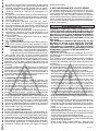
INSTALLER WARNINGS
Anything that is not explicitly provided for in the installation ma-
nual is not allowed. The operator’s proper operation can only be
guaranteed if the information given is complied with. The Firm shall
not be answerable for damage caused by failure to comply with the
instructions featured herein.
While we will not alter the product’s essential features, the Firm reserves
the right, at any time, to make those changes deemed opportune to
improve the product from a technical, design or commercial point of
view, and will not be required to update this publication accordingly.
WARNING! Important safety instructions. Carefully read and comply with
all the warnings and instructions that come with the product as incorrect
installation can cause injury to people and animals and damage to property.
The warnings and instructions give important information regarding safety,
installation, use and maintenance. Keep hold of instructions so that you can
attach them to the technical le and keep them handy for future reference.
GENERAL SAFETY
This product has been designed and built solely for the purpose indicated herein.
Uses other than those indicated herein might cause damage to the product and
create a hazard.
- The units making up the machine and its installation must meet the requirements
of the following European Directives, where applicable: 2004/108/EC, 2006/95/
EC, 2006/42/EC, 89/106/EC, 99/05/EC and later amendments. For all countries
outside the EEC, it is advisable to comply with the standards mentioned, in ad-
dition to any national standards in force, to achieve a good level of safety.
- The Manufacturer of this product (hereinafter referred to as the “Firm”) disclaims
all responsibility resulting from improper use or any use other than that for
which the product has been designed, as indicated herein, as well as for failure
to apply Good Practice in the construction of entry systems (doors, gates, etc.)
and for deformation that could occur during use.
- Installation must be carried out by qualied personnel (professional installer,
according to EN 12635), in compliance with Good Practice and current code.
- Before installing the product, make all structural changes required to produce
safety gaps and to provide protection from or isolate all crushing, shearing and
dragging hazard areas and danger zones in general in accordance with the
provisions of standards EN 12604 and 12453 or any local installation standards.
Check that the existing structure meets the necessary strength and stability
requirements.
- Before commencing installation, check the product for damage.
- The Firm is not responsible for failure to apply Good Practice in the construction
and maintenance of the doors, gates, etc. to be motorized, or for deformation
that might occur during use.
- Make sure the stated temperature range is compatible with the site in which the
automated system is due to be installed.
- Do not install this product in an explosive atmosphere: the presence of ammable
fumes or gas constitutes a serious safety hazard.
- Disconnect the electricity supply before performing any work on the system.
Also disconnect buer batteries, if any are connected.
- Before connecting the power supply, make sure the product’s ratings match the
mains ratings and that a suitable residual current circuit breaker and overcurrent
protection device have been installed upline from the electrical system. Have
the automated system’s mains power supply tted with a switch or omnipolar
thermal-magnetic circuit breaker with a contact separation that provide full
disconnection under overvoltage category III conditions.
- Make sure that upline from the mains power supply there is a residual current
circuit breaker that trips at no more than 0.03A as well as any other equipment
required by code.
- Make sure the earth system has been installed correctly: earth all the metal parts
belonging to the entry system (doors, gates, etc.) and all parts of the system
featuring an earth terminal.
- Installation must be carried out using safety devices and controls that meet
standards EN 12978 and EN 12453.
- Impact forces can be reduced by using deformable edges.
- In the event impact forces exceed the values laid down by the relevant standards,
apply electro-sensitive or pressure-sensitive devices.
- Apply all safety devices (photocells, safety edges, etc.) required to keep the
area free of impact, crushing, dragging and shearing hazards. Bear in mind the
standards and directives in force, Good Practice criteria, intended use, the instal-
lation environment, the operating logic of the system and forces generated by
the automated system.
- Apply all signs required by current code to identify hazardous areas (residual
risks). All installations must be visibly identied in compliance with the provisions
of standard EN 13241-1.
- Once installation is complete, apply a nameplate featuring the door/gate’s data.
- This product cannot be installed on leaves incorporating doors (unless the motor
can be activated only when the door is closed).
- If the automated system is installed at a height of less than 2.5 m or is accessible,
the electrical and mechanical parts must be suitably protected.
- For roller shutter automation only
1) The motor’s moving parts must be installed at a height greater than 2.5 m
above the oor or other surface from which they may be reached.
2) The gearmotor must be installed in a segregated and suitably protected space
so that it cannot be reached without the aid of tools.
- Install any xed controls in a position where they will not cause a hazard, away
from moving parts. More specically, hold-to-run controls must be positioned
within direct sight of the part being controlled and, unless they are key operated,
must be installed at a height of at least 1.5 m and in a place where they cannot
be reached by the public.
- Apply at least one warning light (ashing light) in a visible position, and also
attach a Warning sign to the structure.
- Attach a label near the operating device, in a permanent fashion, with informa-
tion on how to operate the automated system’s manual release.
- Make sure that, during operation, mechanical risks are avoided or relevant
protective measures taken and, more specically, that nothing can be banged,
crushed, caught or cut between the part being operated and surrounding parts.
- Once installation is complete, make sure the motor automation settings are
correct and that the safety and release systems are working properly.
- Only use original spare parts for any maintenance or repair work. The Firm dis-
claims all responsibility for the correct operation and safety of the automated
system if parts from other manufacturers are used.
- Do not make any modications to the automated system’s components unless
explicitly authorized by the Firm.
- Instruct the system’s user on what residual risks may be encountered, on the
control systems that have been applied and on how to open the system manu-
ally in an emergency. give the user guide to the end user.
- Dispose of packaging materials (plastic, cardboard, polystyrene, etc.) in accord-
ance with the provisions of the laws in force. Keep nylon bags and polystyrene
out of reach of children.
WIRING
WARNING! For connection to the mains power supply, use: a multicore cable with
a cross-sectional area of at least 5x1.5mm
2
or 4x1.5mm
2
when dealing with three-
phase power supplies or 3x1.5mm
2
for single-phase supplies (by way of example,
type H05RN-F cable can be used with a cross-sectional area of 4x1.5mm
2
). To con-
nect auxiliary equipment, use wires with a cross-sectional area of at least 0.5 mm
2
.
- Only use pushbuttons with a capacity of 10A-250V or more.
- Wires must be secured with additional fastening near the terminals (for example,
using cable clamps) in order to keep live parts well separated from safety extra
low voltage parts.
- During installation, the power cable must be stripped to allow the earth wire
to be connected to the relevant terminal, while leaving the live wires as short
as possible. The earth wire must be the last to be pulled taut in the event the
cable’s fastening device comes loose.
WARNING! safety extra low voltage wires must be kept physically separate from
low voltage wires.
Only qualied personnel (professional installer) should be allowed to access
live parts.
CHECKING THE AUTOMATED SYSTEM AND MAINTENANCE
Before the automated system is nally put into operation, and during maintenance
work, perform the following checks meticulously:
- Make sure all components are fastened securely.
- Check starting and stopping operations in the case of manual control.
- Check the logic for normal or personalized operation.
- For sliding gates only: check that the rack and pinion mesh correctly with 2 mm
of play along the full length of the rack; keep the track the gate slides on clean
and free of debris at all times.
- For sliding gates and doors only: make sure the gate’s running track is straight
and horizontal and that the wheels are strong enough to take the weight of the
gate.
- For cantilever sliding gates only: make sure there is no dipping or swinging
during operation.
- For swing gates only: make sure the leaves’ axis of rotation is perfectly vertical.
-For barriers only: before opening the door, the spring must be decompressed
(vertical boom).
- Check that all safety devices (photocells, safety edges, etc.) are working properly
and that the anti-crush safety device is set correctly, making sure that the force
of impact measured at the points provided for by standard EN 12445 is lower
than the value laid down by standard EN 12453.
- Impact forces can be reduced by using deformable edges.
- Make sure that the emergency operation works, where this feature is provided.
- Check opening and closing operations with the control devices applied.
- Check that electrical connections and cabling are intact, making extra sure that
insulating sheaths and cable glands are undamaged.
- While performing maintenance, clean the photocells’ optics.
- When the automated system is out of service for any length of time, activate the
emergency release (see “EMERGENCY OPERATION” section) so that the operated
part is made idle, thus allowing the gate to be opened and closed manually.
-
If the power cord is damaged, it must be replaced by the manufacturer or their
technical assistance department or other such qualied person to avoid any risk .
- If “D” type devices are installed (as dened by EN12453), connect in unveried
mode, foresee mandatory maintenance at least every six months
- The maintenance described above must be repeated at least once yearly or at
shorter intervals where site or installation conditions make this necessary.
WARNING!
Remember that the drive is designed to make the gate/door easier to use and
will not solve problems as a result of defective or poorly performed installation
or lack of maintenance
SCRAPPING
Materials must be disposed of in accordance with the regulations in
force. Do not throw away your discarded equipment or used batteries
with household waste. You are responsible for taking all your waste
electrical and electronic equipment to a suitable recycling centre.
DISMANTLING
If the automated system is being dismantled in order to be reassembled at another
site, you are required to:
- Cut o the power and disconnect the whole electrical system.
- Remove the actuator from the base it is mounted on.
- Remove all the installation’s components.
- See to the replacement of any components that cannot be removed or happen
to be damaged.
DECLARATIONS OF CONFORMITY CAN BE FOUND AT http://www.bft-
automation.com/CE
INSTRUCTIONS FOR USE AND ASSEMBLY CAN BE FOUND IN THE DOWN-
LOAD SECTION.
D811766_15
ELI-250 - 3
D811232_11

Fig. 1
2
1
Max. 90°
AVVERTENZE PER L’UTILIZZATORE ( I )
ATTENZIONE! Importanti istruzioni di sicurezza.
Leggere e seguire attentamente le Avvertenze
e le Istruzioni che accompagnano il prodotto
poiché un uso improprio può causare danni a
persone, animali o cose. Conservare le istruzioni
per consultazioni future e trasmetterle ad even-
tuali subentranti nell’uso dell’impianto.
Questo prodotto dovrà essere destinato solo
all’uso per il quale è stato espressamente insta-
llato. Ogni altro uso è da considerarsi improprio
e quindi pericoloso. Il costruttore non può essere
considerato responsabile per eventuali danni
causati da usi impropri, erronei e irragionevoli.
SICUREZZA GENERALE
Nel ringraziarVi per la preferenza accordata a questo
prodotto, la Ditta è certa che da esso otterrete le
prestazioni necessarie al Vostro uso.
Questo prodotto risponde alle norme riconosciute
della tecnica e della disposizioni relative alla sicurezza
se correttamente installato da personale qualicato
ed esperto (installatore professionale).
L’automazione, se installata ed utilizzata corretta-
mente, soddisfa gli standard di sicurezza nell’uso.
Tuttavia è opportuno osservare alcune regole di com-
portamento per evitare inconvenienti accidentali:
- Tenere bambini, persone e cose fuori dal raggio
d’azione dell’automazione, in particolare durante
il movimento.
- Non permettere a bambini di giocare o sostare nel
raggio di azione dell’automazione.
- L’apparecchio può essere utilizzato da bambini di
età non inferiore a 8 anni e da persone con ridotte
capacità siche, sensoriali o mentali, o prive di
esperienza o della necessaria conoscenza, purché
sotto sorveglianza oppure dopo che le stesse
abbiano ricevuto istruzioni relative all’uso sicuro
dell’apparecchio e alla comprensione dei pericoli
ad esso inerenti. I bambini non devono giocare con
l’apparecchio. La pulizia e la manutenzione desti-
nata ad essere eettuata dall’utilizzatore non deve
essere eettuata da bambini senza sorveglianza.
- I bambini devono essere sorvegliati per sincerarsi
che non giochino con l’apparecchio. Non permet-
tere ai bambini di giocare con i controlli ssi. Tenere
i telecomandi lontani dai bambini.
-
Evitare di operare in prossimità delle cerniere o organi
meccanici in movimento.
-
Non contrastare il movimento dell’anta e non ten-
tare di aprire manualmente la porta se non è stato
sbloccato l’attuatore con l’apposita manopola di
sblocco.
-
Non entrare nel raggio di azione della porta o can-
cello motorizzati durante il loro movimento.
- Non lasciare radiocomandi o altri dispositivi di
comando alla portata dei bambini onde evitare
azionamenti involontari.
- L’attivazione dello sblocco manuale potrebbe
causare movimenti incontrollati della porta se in
presenza di guasti meccanici o di condizioni di
squilibrio.
- In caso di apritapparelle: sorvegliare la tapparella
in movimento e tenere lontano le persone nché
non è completamente chiusa. Porre cura quando si
aziona lo sblocco se presente, poiché una tapparella
aperta potrebbe cadere rapidamente in presenza
di usura o rotture.
-
La rottura o l’usura di organi meccanici della porta
(parte guidata), quali ad esempio cavi, molle, sup-
porti, cardini, guide.. potrebbe generare pericoli. Far
controllare periodicamente l’impianto da personale
qualicato ed esperto (installatore professionale)
secondo quanto indicato dall’installatore o dal cos-
truttore della porta.
- Per ogni operazione di pulizia esterna, togliere
l’alimentazione di rete.
- Tenere pulite le ottiche delle fotocellule ed i dispo-
sitivi di segnalazione luminosa. Controllare che rami
ed arbusti non disturbino i dispositivi di sicurezza.
- Non utilizzare l’automatismo se necessita di
interventi di riparazione. In caso di guasto o di
malfunzionamento dell’automazione, togliere
l’alimentazione di rete sull’automazione, astenersi
AVVERTENZE PER L’UTILIZZATORE ( I ) - USER WARNINGS (GB)
AVERTISSEMENTS POUR L’UTILISATEUR(F) - HINWEISE FÜR DEN BENUTZER (D)
ADVERTENCIAS PARA EL USUARIO (E) - ADVERTÊNCIAS PARA O UTILIZADOR (P)
8 - ELI-250
D811232_11

da qualsiasi tentativo di riparazione o intervento
diretto e rivolgersi solo a personale qualicato ed
esperto (installatore professionale) per la neces-
saria riparazione o manutenzione. Per consentire
l’accesso, attivare lo sblocco di emergenza (se
presente).
-
Per qualsiasi intervento diretto sull’automazione o
sull’impianto non previsto dal presente manuale,
avvalersi di personale qualicato ed esperto (insta-
llatore professionale).
- Con frequenza almeno annuale far verifi-
care l’integrità e il corretto funzionamento
dell’automazione da personale qualificato ed
esperto (installatore professionale), in particolare
di tutti i dispositivi di sicurezza.
- Gli interventi d’installazione, manutenzione e
riparazione devono essere documentati e la
relativa documentazione tenuta a disposizione
dell’utilizzatore.
- Il mancato rispetto di quanto sopra può creare
situazioni di pericolo.
DEMOLIZIONE
L’eliminazione dei materiali va fatta rispettan-
do le norme vigenti. Non gettate il vostro
apparecchio scartato, le pile o le batterie usate
nei riuti domestici. Avete la responsabilità di
restituire tutti i vostri riuti da apparecchia-
ture elettriche o elettroniche lasciandoli in
un punto di raccolta dedicato al loro riciclo.
Tutto quello che non è espressamente previsto
nel manuale d’uso, non è permesso. ll buon fun-
zionamento dell’operatore è garantito solo se ven-
gono rispettate le prescrizioni riportate in questo
manuale. La Ditta non risponde dei danni causati
dall’inosservanza delle indicazioni riportate in questo
manuale.
Lasciando inalterate le caratteristiche essenziali del
prodotto, la Ditta si riserva di apportare in qualunque
momento le modiche che essa ritiene convenienti
per migliorare tecnicamente, costruttivamente e
commercialmente il prodotto, senza impegnarsi ad
aggiornare la presente pubblicazione.
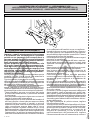
1) MANOVRA DI EMERGENZA
Lo sblocco di emergenza si eettua agendo, con
l’apposita chiave in dotazione, sul gruppetto sblocco
situato sotto il cancello sulla parte sporgente della
leva-perno. Per sbloccare, inserire la chiave nel trian-
golo di sblocco e ruotare la chiave verso l’indicazione
del lucchetto aperto per circa 90° (g.1).
Se l’anta è dotata di elettroserratura, sbloccare
anche l’elettroserratura. Spingere manualmente
l’anta per aprire/chiudere il cancello. Per ripristi-
nare l’operazione motorizzata, riposizionare il
cancello allineato con la leva che porta il gruppo
blocco e girare la chiave verso l’indicazione del
lucchetto chiuso (g.1) avendo cura di controllare
l’avvenuto aggancio dell’anta. Riporre la chiave di
sblocco anta (e dell’elettroserratura se presente) in
luogo conosciuto agli utilizzatori.
2) USO DELL’AUTOMAZIONE
Poichè l’automazione può essere comandata a di-
stanza mediante radiocomando o pulsante di Start,
e quindi non a vista, è indispensabile controllare
frequentemente la perfetta ecienza di tutti i di-
spositivi di sicurezza. Per qualsiasi anomalia di fun-
zionamento, intervenire rapidamente avvalendosi
di personale qualicato. Si raccomanda di tenere
i bambini a debita distanza dal raggio di azione
dell’automazione.
3) MALFUNZIONAMENTO: CAUSE E RIMEDI
Per qualsiasi anomalia di funzionamento non risol-
ta, togliere l’alimentazione al sistema e chiedere
l’intervento di personale qualicato (installatore).
Nel periodo di fuori servizio, attivare lo sblocco
manuale per consentire l’apertura e la chiusura ma-
nuale. In questo periodo, per mantenere il blocco in
chiusura, provvedere a mantenerlo chiuso mediante
catena e lucchetto.
USER WARNINGS (GB)
WARNING! Important safety instructions. Ca-
refully read and comply with the Warnings and
Instructions that come with the product as impro-
per use can cause injury to people and animals
and damage to property. Keep the instructions
for future reference and hand them on to any
new users.
This product is meant to be used only for the
purpose for which it was explicitly installed.
Any other use constitutes improper use and,
consequently, is hazardous. The manufacturer
cannot be held liable for any damage as a result
of improper, incorrect or unreasonable use.
GENERAL SAFETY
Thank you for choosing this product. The Firm is
condent that its performance will meet your ope-
rating needs.
This product meets recognized technical standards
and complies with safety provisions when installed
correctly by qualied, expert personnel (professional
installer).
If installed and used correctly, the automated system
will meet operating safety standards. Nonetheless,
it is advisable to observe certain rules of behaviour
so that accidental problems can be avoided:
- Keep adults, children and property out of range of
the automated system, especially while it is moving.
- Do not allow children to play or stand within range
of the automated system.
- The unit can be used by children over 8 years old
and by people with reduced physical, sensory or
mental capabilities or with no experience or neces-
sary knowledge on condition they are supervised
or trained about the safe use of the equipment
and understand the risks involved. Children must
not play with the unit. Cleaning and maintenance
must not be performed by unsupervised children.
- Children must be supervised to ensure they do not
play with the device. Do not allow children to play
with the xed controls. Keep remote controls out
of reach of children.
-
Do not work near hinges or moving mechanical parts.
- Do not hinder the leaf’s movement and do not
attempt to open the door manually unless the ac-
tuator has been released with the relevant release
knob.
- Keep out of range of the motorized door or gate
while they are moving.
- Keep remote controls or other control devices out
of reach of children in order to avoid the automated
system being operated inadvertently.
- The manual release’s activation could result in un-
controlled door movements if there are mechanical
faults or loss of balance.
- When using roller shutter openers: keep an eye
on the roller shutter while it is moving and keep
ELI-250 - 9
D811232_11

people away until it has closed completely. Exercise
care when activating the release, if such a device
is tted, as an open shutter could drop quickly in
the event of wear or breakage.
- The breakage or wear of any mechanical parts of
the door (operated part), such as cables, springs,
supports, hinges, guides…, may generate a hazard.
Have the system checked by qualied, expert per-
sonnel (professional installer) at regular intervals
according to the instructions issued by the installer
or manufacturer of the door.
- When cleaning the outside, always cut o mains
power.
- Keep the photocells’ optics and illuminating in-
dicator devices clean. Check that no branches or
shrubs interfere with the safety devices.
- Do not use the automated system if it is in need of
repair. In the event the automated system breaks
down or malfunctions, cut o mains power to the
system; do not attempt to repair or perform any
other work to rectify the fault yourself and instead
call in qualied, expert personnel (professional
installer) to perform the necessary repairs or main-
tenance. To allow access, activate the emergency
release (where tted).
- If any part of the automated system requires direct
work of any kind that is not contemplated herein,
employ the services of qualied, expert personnel
(professional installer).
- At least once a year, have the automated system, and
especially all safety devices, checked by qualied,
expert personnel (professional installer) to make
sure that it is undamaged and working properly.
- A record must be made of any installation, main-
tenance and repair work and the relevant docu-
mentation kept and made available to the user on
request.
- Failure to comply with the above may result in
hazardous situations.
SCRAPPING
Materials must be disposed of in accordance
with the regulations in force. Do not throw
away your discarded equipment or used bat-
teries with household waste. You are respon-
sible for taking all your waste electrical and
electronic equipment to a suitable recycling
centre.
Anything that is not explicitly provided for in the
user guide is not allowed. The operator’s proper
operation can only be guaranteed if the instruc-
tions given herein are complied with. The Firm
shall not be answerable for damage caused by
failure to comply with the instructions featured
herein.
While we will not alter the product’s essential
features, the Firm reserves the right, at any time,
to make those changes deemed opportune to
improve the product from a technical, design or
commercial point of view, and will not be required
to update this publication accordingly.
1) EMERGENCY MANOEUVRE
Emergency release is obtained by using the key pro-
vided, on the release unit which is located under the
gate, on the protruding section of the lever-pivot.
To release, insert the key in the release triangle and
turn it by about 90° in the direction shown by the
open-padlock symbol (g.1). If the leaf is equipped
with an electric lock, release the electric lock as
well. To open/close the gate, push it manually. To
restore motor-driven operation, reposition the gate
by aligning it with the lever bearing the lock unit, and
turn the key in the direction shown by the closed-
padlock symbol (g.1) checking that engagement
is correctly restored. Keep the leaf release key (and
that of the electric lock, if any) in a place which is
known to the users.
2) AUTOMATION OPERATION
Since the automation system can be remotely
controlled by means of a radio control device or a
Start button, and therefore out of sight, all safety
devices must be frequently checked in order to
ensure their perfect eciency. In the event of any
anomalous operation, request immediate assistance
from qualied personnel. Children must be kept at
a safe distance from the automation operation area.
3) MALFUNCTION: CAUSES AND REMEDIES
When any operational malfunction is found,
and not resolved, disconnect the mains power
supply and request the assistance of a qualied
technician (installer).
When automation is out of order, activate the manual
release to allow the opening and closing operations
to be carried out manually.
During this period of time, keep the lock in the closed
position by means of a chain and padlock.
AVERTISSEMENTS POUR L’UTILISATEUR (F)
ATTENTION ! Instructions de sécurité importan-
tes. Veuillez lire et suivre attentivement tous les
avertissements et toutes les instructions fournis
avec le produit sachant qu’un usage incorrect
peut provoquer des préjudices aux personnes,
aux animaux ou aux biens. Veuillez conserver
les instructions pour d’ultérieures consultations
et pour les transmettre aux propriétaires futurs
éventuels.
Cet appareil ne peut être destiné qu’à l’usage
pour lequel il a été expressément installé. Tout
autre usage sera considéré comme impropre et
donc dangereux. Le fabricant ne sera en aucun
cas considéré comme responsable des préjudices
dus à un usage impropre, erroné ou déraisonné.
SECURITE GÉNÉRALE
Nous vous remercions d’avoir choisi ce produit
qui, nous n’en doutons pas, saura vous garantir les
performances attendues.
Ce produit, correctement installé par du personnel
qualié et expérimenté (monteur professionnel) est
conforme aux normes reconnues de la technique et
des prescriptions de sécurité.
Si l’automatisation est montée et utilisée correcte-
ment, elle garantit la sécurité d’utilisation prescrite.
Il est cependant nécessaire de respecter certaines
règles de comportement pour éviter tout inconvé-
nient accidentel.
- Tenir les enfants, les personnes et les objets à l’écart
du rayon d’action de l’automatisation, en particulier
pendant son fonctionnement.
- Empêcher les enfants de jouer ou de stationner
dans le rayon d’action de l’automatisation.
- Les enfants de plus de 8 ans et les personnes ayant
des capacités physiques, sensorielles ou mentales
diminuées ou n’ayant pas l’expérience et les con-
naissances nécessaires peuvent utiliser l’appareil
à condition d’être sous la surveillance d’un adulte
10 - ELI-250
D811232_11
ELI-250 - 10

Fig. 1
Fig. 2
AL
S
Fre
M
E
M
D
Fte
I
Qr
3x1mm
2
4x1.5mm
2
4x1.5mm
2
4x1mm
2
2x1mm
2
4x1mm
2
2x1mm
2
2x1.5mm
2
2x1.5mm
2
3x1.5mm
2
RG58
Fri
CF
Fti
CF
D
T
16 - ELI-250
D811232_11

Fig. 4Fig. 3
Fig. 6
Fig. 5
180
S
500
400
336
420
70
145
min. 70
D
D
ELI-250 - 17
D811232_11

Fig. 8
Fig. 9
A
C
V1
19
V1
20
6
10
FA FA
FA
DX
SX
18 - ELI-250
D811232_11

Fig. 11Fig. 10
Fig. 13B
Fig. 11B
Fig. 12
C
12
4
V1
5
C1
VRO
L2
VRC
C1
VRC
VRC
L1
C1
V1
5°
5°
ELI-250 - 19
D811232_11

Fig. 14
2
1
Max. 90°
20 - ELI-250
D811232_11

ENGLISH
INSTALLATION MANUAL
Thank you for buying this product, our company is sure that you will be more
than satised with the performance of the product. This product is supplied
with a “Warnings” leaet and an “Instruction manual”. These should both be
read carefully as they provide important information about safety, installation,
operation and maintenance.
WARNINGS: Any assistance required on automation components must be
carried out by a qualied technician (installer).
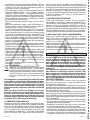
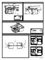
2) GENERAL OUTLINE
The ELI-250 electromechanical actuator is the ideal solution for underground
hinge-pivot installation. The actuator consists of a perfectly sealed single-block
reduction gear. The under hinge-pivot position maintains the aesthetic appearance
of the gate and practically hides the automation system.
Once the bearing case is installed, the gate can be operated even without tting
the actuator which can be inserted later. When maintenance is required, this type
of case allows the actuator to be taken out without removing the gate leaf. The
ELI-250 actuator can be tted to any type of swing gate which meets the values
shown in the ”Technical Specications” table. The pushing force is set on the
control unit (see specic manual).
The end-of-stroke operation is adjusted by mechanical stops located inside the
foundation case.
CAUTION! The actuator mod. ELI-250 is not provided with mechanical torque
adjustment. It is compulsory to use a control board of the same manufactu-
rer, according to the basic safety requirements of directives 2004/108/EEC,
2006/95/EEC, 2006/42/EEC, 99/05/EEC and provided with adequate electric
torque adjustment.
3) MAIN AUTOMATION PARTS
Sealed mechanical actuator (g.1) including:
a) Single-phase 2-pole motor protected by thermal circuit-breaker.
b) Double worm-screw reduction gear with output gear in special aluminium
alloy.
c) Output lever and mechanical stops.
d) Bearing foundation case (ready for automation).
e) Series of levers for gate movement.
f) Release unit with key.
CAUTION! The actuator can be tted either on the left or on the right, which are
conventionally dened by looking at the gate from the inside (opening direction).
4) TECHNICAL SPECIFICATIONS
Single-phase power supply ............................................................. 220-230V 50/60Hz(*)
Motor revolutions......................................................................................................1400min
-1
Output shaft revolutions ......................................ELI250 0.95min
-1
- ELI250V 1.9min
-1
Absorbed power ................................................................................................................ 280W
Capacitor ................................................................................................................................10µF
Absorbed current .................................................................................................................1,4A
Opening time 120° ....................................................................... ELI250 28s - ELI250V 14s
Max torque.......................................................................ELI250 380Nm - ELI250V 240Nm
Max leaf length/weight ................................................. ELI250 2.5m/3000N (~300kg)
ELI250 3.5m/2500N (~250kg)
ELI250V 2m/1500n (~150kg)
Max. leaf opening .................................................................................................................120°
Blocking function ..........................................................................................................................
Irreversible gearmotor; electric lock ...........necessary for leaves longer than 2,5m
Impact reaction .................................................... Electronic clutch (with control panel)
Manual manoeuvre ...............................................................................................Release key
Max. no. manoeuvres in 24 hours.................................................................................... 100
Thermal protection ................................................................................130°C self-resetting
Environmental conditions ..................................................................from -20°C to +50°C
Lubrication .................................................................................................. Permanent grease
Degree of protection................................................................................................... IP67 AM
Actuator weight .................................................................................................100N (~ 10kg)
Overall dimensions ...................................................................................................... See g.3
Sound pressure ......................................................................................................LpA<70dbA
(*) Special voltages on request.
5) ACTUATOR INSTALLATION
5.1) Preliminary checks
Check that:
• Theupperhingeisingoodconditionandpossiblyadjustable.
• Aholecanbedugforburyingthecaseunderthehinge.
• The”FA”stopplatesoftheleavesareinstalled(g.8).
• Repairorreplacethefaultyorwornpartsofthestructurestobesubjectedto
movement.
An exploded view of the installation is shown in g.1.
The automation reliability and safety are directly inuenced by the state
of the gate structure.
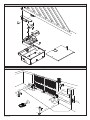
5.2) The main automation components are (Fig.2):
I) Type-approved adequately rated omnipolar circuit breaker with at least
3,5 mm contact opening, provided with protection against overloads and
short circuits, suitable for cutting out automation from the mains. Place,
if not al ready installed, a type-approved dierential switch with a 0.03A
threshold just before the automation system.
Qr) Control panel and built-in receiver.
S) Key selector.
AL) Blinker with tuned antenna.
M) Actuator.
E) Electric lock (compulsory for leaves longer than 2,5m).
Fte) Pair of external photocells (transmitter section).
Fre) Pair of external photocells (receiver section).
Fti) Pair of internal photocells with CF posts (transmitter section).
Fri) Pair of internal photocells with CF posts (receiver section).
T) 1-2-4 channel transmitter.
RG58)
Cable for antenna.
D) Connector block.
5.3) Electrical installation set-up
Lay out the electrical installation as shown in g. 2, with reference to the CEI 64-8
and IEC 364 provisions, complying with the HD 384 and other national standards
in force for electrical installation. The mains power supply connections must be
kept totally separate from the service connections (photocells, electric edges,
control devices etc.).
WARNING! For connection to the mains power supply, use a multicore cable
with a cross-sectional area of at least 3x1.5mm
2
of the kind provided for by
the regulations in force.
To connect the motors, use a cable with a cross-sectional area of at least
1.5mm
2
of the kind provided for by the regulations in force.
The cable must be type H05RN-F at least.
Connect the control and safety devices in compliance with the previously men-
tioned electrical installation standards. Fig. 2 shows the number of connections
and the cross section for cables having a length of approximately 100 metres; in
case of longer cables, calculate the cross section for the actual automation load.
Warning! For actuator wiring and accessory connection, refer to the relevant
instruction manuals. The control panels and accessories must be suitable for use
and conform to current standards.
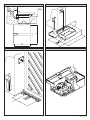
5.4) Foundation case cementing
The foundation case must be cemented under the hinge pivot, taking into con-
sideration that the actuator bearing shaft must be perfectly aligned with the leaf
rotation axis. If the gate has xed hinges, remove the gate and the lower hinge.
If the leaf is suciently separated from the ground and cannot be removed,
proceed to supporting it by means of a shim placed between the ground and
the leaf during installation. If the gate has adjustable hinges, remove the lower
one, slacken the upper hinge and move the leaf to the side. If the gate has been
recently installed, t an upper adjustable hinge. Dig a foundation hole having the
dimensions specied in g.4. Lay an drain pipe (g. 4) for rainwater in order to
prevent it from being collected inside the foundation case. Lay a raceway for the
power supply cable as far as connector block “D”. Lay a solid foundation (g.3) at the
bottom, where to bury the foundation box. To obtain good squareness between
cases and leaves, set out their alignment using a stretched rope between the 2
bearing pivots, and aligning the 2 reference points “C” with each other (see g.12).
Let the cement harden for the time needed.
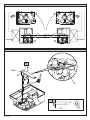
6) GATE LEAF FITTING
• Abundantlygreasethepivotinthefoundationcase.
• Positiontheleverassemblybyinsertingpipe“A”intothepivotofthefoundation
case, as in g.9. If the height of the assembled levers is not sucient, insert
shim “S” between the assembled lever unit and the gate leaf, as in g.5.
• Placethegateleavesintheclosingandintheclosedpositionagainstthecentre
stop plate.
• Perfectlyaligntheassembledleverunittothehinge.
• Ifashimisused,weldittotheleafrstandthenweldtheleverunitto
the shim.
• Checktheleafoperation.
• Ifthegearmotorisnottobeinstalled,tthefoundationcasecoverandxwith
suitable screws.
At this stage, the gate opens and closes manually. All that remains to be done
is to position the gearmotor.
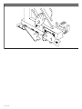
7) GEARMOTOR FITTING
Remove the nuts from the bottom of the case using a CH19 socket wrench.
The gearmotor is to be xed to the foundation case in the position shown in g.6
and 8, using the 4 nuts which were previously removed.
• Fit the motor-pivot connecting lever components following the correct
sequence given in g.9.
In the case where the position of the levers interferes with the assembly of
the components, supply the motors with current (by means of the control
unit) until the levers reach the required position.
• Fig.9: insert the greaser (C) into the threaded hole of the lever (A). The type
of grease recommended is: Rocol Foodlube Multipaste.
• Greasethehubwherepipe“A”mustbeinserted.
• Checktheopeningandclosingoperations.
• Attachtotheleaftheinternalandexternalreleaselabelsobservingthedirec-
tion and position indicated in g.14. The open-padlock symbol must always
be directed towards the leaf rotation axis.
• Connectionofthegearmotorcablemustbecarriedoutinajunctionbox
positioned outside the foundation case without cutting the cable supplied
ELI-250 - 23
D811232_11

INSTALLATION MANUAL
as standard (Fig.2-4-5 Ref.D).
8) END-OF-STROKE ADJUSTMENT
If no ground stop plates “FA” are tted, adjust the internal stops using the screws
“VRC-VRO” (g.10-11) until the leaf stops at the required point.
The mechanical stop for the opening and closing operations can be adjusted by
means of the appropriate screws “VRC-VRO”.
• OnCLOSING (g.10): Tighten the limit stop adjustment screw “VRC” until it
engages with lever “L1” once the leaf has stopped in the position corresponding
to CLOSED.
•
On OPENING (g.11): Tighten the limit stop adjustment screw “VRO” until it engages
with lever “L2” once the leaf has stopped in the position corresponding to OPEN.
• Onceyouhavenishedadjustment,tightenscrewsV1,whichlockthelimit
stop adjustment grub screws (VRC/VRO), Fig. 11B.
• Repeatthesameprocedureforthesecondactuator.
• Ifthefoundationcaseisnotorthogonaltotheleaf,a5%adjustmentcanbe
carried out both in clockwise and anticlockwise directions.
9) MOTOR TORQUE SETTING
CAUTION! When using the ARIES mod. control unit with the torque set to “F4”
(maximum torque), it is compulsory to t the ground stop plates “FA” both on
opening and closing.
The motor torque (antisquash) setting takes place in the control unit. See the control
unit instruction manual. The wiring diagram of the motor is included in the instructions
for use for the relative control unit. This setting must be calibrated according to the
minimum force needed to carry out the complete opening and closing strokes, and
always within the limits provided for by current standards.
CAUTION! Excessive torque setting can jeopardise antisquash safety. On the
contrary, insucient torque setting may not guarantee a correct opening or
closing stroke.
10) EMERGENCY MANOEUVRE
Emergency release is obtained by using the key provided, on the release unit
which is located under the gate, on the protruding section of the lever-pivot.
To release, insert the key in the release triangle and turn it by about 90° in the
direction shown by the open-padlock symbol (g.14). If the leaf is equipped with
an electric lock, release the electric lock as well.
To open/close the gate, push it manually. To restore motor-driven operation,
reposition the gate by aligning it with the lever bearing the lock unit, and turn
the key in the direction shown by the closed-padlock symbol (g.14) checking
that engagement is correctly restored. Keep the leaf release key (and that of the
electric lock, if any) in a place which is known to the users.
11) AUTOMATION CHECK
Before making the automation fully operational, carefully carry out the following
procedure:
• Checkthatallcomponentsaretightlyxed.
•
Check the correct operation of all safety devices (photocells, electric edges etc.).
• Checktheemergencymanoeuvrecommand.
• Checktheopeningandclosingoperationswiththecontroldevices
provided.
• Checkthestandardorcustomisedelectronicfunctionlogic.
12) AUTOMATION OPERATION
Since the automation system can be remotely controlled by means of a radio
control device or a Start button, and therefore out of sight, all safety devices must
be frequently checked in order to ensure their perfect eciency. In the event of
any anomalous operation, request immediate assistance from qualied personnel.
Children must be kept at a safe distance from the automation operation area.
13) CONTROL
The automation system allows motor-driven gate opening and closing operations
to be carried out. Various types of control are provided (manual, radio control,
magnetic card access control etc.) depending on the installation requirements
and characteristics. See the specic instructions for the various control systems. All
automation system users must be instructed on automation control and operation.
14) MAINTENANCE
Before carrying out any maintenance to the installation, disconnect the mains
power supply.
• Periodicallycheckthathinge-pivotsareingoodconditionandproperly
greased.
• Greasethepinonthefoundationcaseeverytwoyears,usingtheappropriate
greaser (C) located on the lever (A) as shown in Fig.9.
The type of grease recommended is: Rocol Foodlube Multipaste.
• Occasionallycleanthephotocellopticalcomponents.
• Haveaqualiedtechnician(installer)checkthecorrectsettingoftheelectric
clutch.
• Ifthepowersupplycableisdamaged,itmustbereplacedbythemanufacturer
or its technical assistance service, or else by a suitably qualied person, in
order to prevent any risk.
• Whenanyoperationalmalfunctionis found,andnotresolved,disconnect
the mains power supply and request the assistance of a qualied technician
(installer). When automation is out of order, activate the manual release to
allow the opening and closing operations to be carried out manually.
15) NOISE
The aerial noise produced by the gearmotor under normal operating conditions
is constant and does not exceed 70dB(A).
16) MALFUNCTION: CAUSES AND REMEDIES
When any operational malfunction is found, and not resolved, disconnect
the mains power supply and request the assistance of a qualied tech-
nician (installer).
When automation is out of order, activate the manual release to allow the opening
and closing operations to be carried out manually.
During this period of time, keep the lock in the closed position by means of a
chain and padlock.
16.1) The gate does not open. The motor does not turn.
a) Check that the photocells or electric edges are not dirty, or impregnated, or
misaligned. Proceed accordingly.
b) Check that the electronic appliance is correctly supplied. Check the integrity
of the fuses.
c) Check that the individual devices operate correctly.
d) If the control unit does not work, it must be replaced.
In the case where the above-mentioned checks give no results, contact an
authorised customer service centre.
If the supply cable is damaged, it must be replaced by the manufacturer,
by its technical service center or, in any case, by a qualied technician so
as to avoid any risk.
16.2) The gate does not open. The actuator vibrates but there is no movement.
a) Check that the capacitor is connected to the motor running terminals.
b) Check that the common wire of the motor (light blue) is correctly connected.
c) Disconnect and reconnect the mains power supply. The rst Start command
must open. Should the actuator move to the closing function, reverse the
respective running connections.
d) Manually help the leaf opening operation. If the leaf opens, check whether
there are any mechanical problems. In the case where the above-mentioned
checks give no results, increase the torque in the control unit and, if necessary,
contact a qualied technician.
24 - ELI-250
D811232_11
-
 1
1
-
 2
2
-
 3
3
-
 4
4
-
 5
5
-
 6
6
-
 7
7
-
 8
8
-
 9
9
-
 10
10
-
 11
11
-
 12
12


BFT ELI 250 Manuale utente
- Tipo
- Manuale utente
- Questo manuale è adatto anche per
in altre lingue
- English: BFT ELI 250 User manual
Documenti correlati
-
BFT Eli 250 BT Manuale utente
-
-
-
-
-
-
-
-
-
