ISTRUZIONI DI INSTALLAZIONE
INSTALLATION MANUAL
INSTRUCTIONS D’INSTALLATION
MONTAGEANLEITUNG
INSTRUCCIONES DE INSTALACION
INSTRUÇÕES DE USO E DE INSTALAÇÃO
AUTOMAZIONI A BRACCIO PER CANCELLI A BATTENTE
ARM AUTOMATIONS FOR SWING GATES
AUTOMATIONS A BRAS POUR PORTAILS BATTANTS
ARM AUTOMATIONEN FUER FLUGELGITTERTIRE
AUTOMATIZACIONES A BRAZO PARA PORTONES CON BATIENTE
AUTOMATIZAÇÕES DE BRAÇO PARA PORTÕES DE BATENTE
Attenzione! Leggere attentamente le “Avvertenze” all’interno! Caution! Read “Warnings” inside carefully! Attention! Veuillez lire attentivement les Avertissements qui se trouvent à l’intérieur!
Achtung! Bitte lesen Sie aufmerksam die „Hinweise“ im Inneren! ¡Atención¡ Leer atentamente las “Advertencias”en el interior! Atenção! Ler atentamente as “Instruções “ que se encontram no interior!
D811296_09 14-05-15
IGEA
8
027908 1 7 1 9 9 3

Fig. 2Fig. 1 Fig. 3
Fig. 5
Fig. 4
180˚
MAX
300
165
SX
315 MIN
20
170
165
SX
315 MIN
110
170
220
146
360
93˚
170
110
700
600
MAX 300
Fig. A
Fig. 6 Fig. 7
Fig. 8
1015
Sinistra / Left / Gauche / Linke / Izquierdo / Esquerda
Destra/Right/Droite / Rechts / Derecha / Direita
F
S
S
S
S
CORRETTO / RIGHT / JUSTE / RICHTIG / CORRECTO / JUSTO:
NON CORRETTO / WRONG / FAUX / FALSCH / NO CORRECTO / ERRADO:
Sinistra / Left
Gauche / Linke
Izquierdo / Esquerda
Destra / Right
Droite / Rechts
Derecha / Direita
2 - IGEA
D811296_09

Fig. 10
Fig. 9
T
CF
CF
M
AL
S
QR
I
M
Fti
Fri
2x1mm
2
4x1.5mm
2
4x1.5mm
2
4x1mm
2
4x1mm
2
3x1mm
2
RG58
2x1.5mm
2
2x1.5mm
2
3x1.5mm
2
Fre
Fte
LEFT
LEFT
LEFT
RIGHT
RIGHT
RIGHT
C
A
B
D
C
D
F
E
G
C
3
1
2
D
C
D
Fig. 9b
Fig. 9c
D
D
D
ITALIANO
ENGLISH
FRANÇAIS
DEUTSCH
ESPAÑOL
PORTUGUÊS
IGEA - 3
D811296_09

Fig. 11
Fig. 12
F2
F1
3
2
NERO-BLACK-NOIR-SCHWARZ-NEGRO-PRETO
MARRONE-BROWN-MARRON-BRAUN-MARON-CASTANHO
CELESTE-SKY-BLUE-BLEU CLAIR-HELLBLAU-AZUL-CELESTE
GND
PG11
M
F1-NC
F1-COM
F2-NC
F2-COM
CM
M
L
230V
N
1
M
F1 F2 1 2 3
FC2
FC1
R - FC2
FC2
FC1
R - FC1
R - FC1
R - FC2
FC2
FC1
Fig. 13
Fig. 14
SX (LEFT)
DX (RIGHT)
RIGHT
LEFT
OPEN S FC1
CLOSE S FC2
CLOSE D FC1
OPEN D FC2
4 - IGEA
D811296_09

Fig. 15
1
LEFT
RIGHT
1
2
3 3
2
D
ø 5 mm
Fig. 16
ITALIANO
ENGLISH
FRANÇAIS
DEUTSCH
ESPAÑOL
PORTUGUÊS
IGEA - 5
D811296_09

ENGLISH
INSTALLER WARNINGS
Anything that is not explicitly provided for in the installation ma-
nual is not allowed. The operator’s proper operation can only be
guaranteed if the information given is complied with. The Firm shall
not be answerable for damage caused by failure to comply with the
instructions featured herein.
While we will not alter the product’s essential features, the Firm reserves
the right, at any time, to make those changes deemed opportune to
improve the product from a technical, design or commercial point of
view, and will not be required to update this publication accordingly.
WARNING! Important safety instructions. Carefully read and comply with
all the warnings and instructions that come with the product as incorrect
installation can cause injury to people and animals and damage to property.
The warnings and instructions give important information regarding safety,
installation, use and maintenance. Keep hold of instructions so that you can
attach them to the technical le and keep them handy for future reference.
GENERAL SAFETY
This product has been designed and built solely for the purpose indicated herein.
Uses other than those indicated herein might cause damage to the product and
create a hazard.
- The units making up the machine and its installation must meet the requirements
of the following European Directives, where applicable: 2004/108/EC, 2006/95/
EC, 2006/42/EC, 89/106/EC, 99/05/EC and later amendments. For all countr
ies
outside the EEC, it is advisable t
o comply with the standards mentioned, in ad-
dition to any national standards in force, to achieve a good level of safety.
- The Manufacturer of this product (hereinafter referred to as the “Firm”) disclaims
all responsibility resulting from improper use or any use other than that for
which the product has been designed, as indicated herein, as well as for failure
to apply Good Practice in the construction of entry systems (doors, gates, etc.)
and for deformation that could occur during use.
- Installation must be carried out by qualied personnel (professional installer
,
ac
cording to EN 12635), in compliance with Good Practice and current code.
- Before installing the product, make all structural changes required to produce
safety gaps and to provide protection from or isolate all crushing, shearing and
dragging hazard areas and danger zones in general in accordance with the
provisions of standards EN 12604 and 12453 or any local installation standards.
Check that the existing structure meets the necessary strength and stability
requirements.
- Before commencing installation, check the product for damage.
- The Firm is not responsible for failure to apply Good Practice in the construction
and maintenance of the doors, gates, etc. to be motorized, or for deformation
that might occur during use.
- Make sure the stated temperature range is compatible with the site in which the
automated system is due to be installed.
- Do not install this product in an explosive atmosphere: the presence of ammable
fumes or gas constitutes a serious safety hazard.
- Disconnect the electricity supply before performing any work on the syst
em.
A
lso disconnect buer batteries, if any are connected.
- Before connecting the power supply, make sure the product’s ratings match the
mains ratings and that a suitable residual current circuit breaker and overcurrent
protection device have been installed upline from the electrical system. Hav
e
the aut
omated system’s mains power supply tted with a switch or omnipolar
thermal-magnetic circuit breaker with a contact separation that provide full
disconnection under overvoltage category III conditions.
- Make sure that upline from the mains power supply there is a residual current
circuit breaker that trips at no more than 0.03A as well as any other equipment
required by code.
- Make sure the earth system has been installed correctly: earth all the metal parts
belonging to the entry system (doors, gates, etc.) and all parts of the syst
em
f
eaturing an earth terminal.
- Installation must be carried out using safety devices and controls that meet
standards EN 12978 and EN 12453.
- Impact forces can be reduced by using deformable edges.
- In the event impact forces exceed the values laid down by the relevant standards,
apply electro-sensitive or pressure-sensitive devices.
- Apply all safety devices (photocells, safety edges, etc.) required to keep the
area free of impact, crushing, dragging and shearing hazards. Bear in mind the
standards and directives in force, Good Practice criteria, intended use, the instal-
lation environment, the operating logic of the system and forces generated by
the automated system.
- Apply all signs required by current code to identify hazardous areas (r
esidual
r
isks). All installations must be visibly identied in compliance with the provisions
of standard EN 13241-1.
- Once installation is complete, apply a nameplate featuring the door/gate’s data.
- This product cannot be installed on leaves incorporating doors (unless the motor
can be activated only when the door is closed).
- If the automated system is installed at a height of less than 2.5 m or is accessible,
the electrical and mechanical parts must be suitably protected.
- Install any xed controls in a position where they will not cause a hazard, away
from moving parts. More specically, hold-to-run controls must be positioned
within direct sight of the part being controlled and, unless they are key operated,
must be installed at a height of at least 1.5 m and in a place where they cannot
be reached by the public.
- Apply at least one warning light (ashing ligh
t) in a visible position, and also
a
ttach a Warning sign to the structure.
- Attach a label near the operating device, in a permanent fashion, with informa-
tion on how to operate the automated system’s manual release.
- Make sure that, during operation, mechanical risks are avoided or relevant
protective measures taken and, more specically, that nothing can be banged,
crushed, caught or cut between the part being operated and surrounding parts.
- Once installation is complete, make sure the motor automation settings are
correct and that the safety and release systems are working properly.
- Only use original spare parts for any maintenance or repair work. The Firm dis-
claims all responsibility for the correct operation and safety of the automat
ed
sy
stem if parts from other manufacturers are used.
- Do not make any modications to the automated system’s components unless
explicitly authorized by the Firm.
- Instruct the system’s user on what residual risks may be encountered, on the
c
ontrol systems that have been applied and on how to open the system manu-
ally in an emergency. give the user guide to the end user.
- Dispose of packaging materials (plastic, cardboard, polystyrene, etc.) in accord-
ance with the provisions of the laws in force. Keep nylon bags and polystyrene
out of reach of children.
WIRING
WARNING! For connection to the mains power supply, use: a multicore cable with
a cross-sectional area of at least 5x1.5mm
2
or 4x1.5mm
2
when dealing with three-
phase power supplies or 3x1.5mm
2
for single-phase supplies (by way of example,
type H05 VV-F cable can be used with a cross-sectional area of 4x1.5mm
2
). To con-
nect auxiliary equipment, use wires with a cross-sectional area of at least 0.5 mm
2
.
- Only use pushbuttons with a capacity of 10A-250V or more.
- Wires must be secured with additional fastening near the terminals (for example,
using cable clamps) in order to keep live parts well separated from safety extra
low voltage parts.
- During installation, the power cable must be stripped to allow the earth wire
to be connected to the relevant terminal, while leaving the live wires as short
as possible. The earth wire must be the last to be pulled taut in the event the
cable’s fastening device comes loose.
WARNING! safety extra low voltage wires must be kept physically separate from
low voltage wires.
Only qualied personnel (professional installer) should be allowed to access
live parts.
CHECKING THE AUTOMATED SYSTEM AND MAINTENANCE
Before the automated system is nally put into operation, and during maintenance
work, perform the following checks meticulously:
- Make sure all components are fastened securely.
- Check starting and stopping operations in the case of manual control.
- Check the logic for normal or personalized operation.
- For sliding gates only: check that the rack and pinion mesh correctly with 2 mm
of play along the full length of the rack; keep the track the gate slides on clean
and free of debris at all times.
- For sliding gates and doors only: make sure the gate’s running track is straight
and horizontal and that the wheels are strong enough to take the weight of the
gate.
- For cantilever sliding gates only: make sure there is no dipping or swinging
during operation.
- For swing gates only: make sure the leaves’ axis of rotation is perfectly vertical.
-For barriers only: before opening the door, the spring must be decompressed
(vertical boom).
- Check that all safety devices (photocells, safety edges, etc.) are working properly
and that the anti-crush safety device is set correctly, making sure that the force
of impact measured at the points provided for by standard EN 12445 is lower
than the value laid down by standard EN 12453.
- Impact forces can be reduced by using deformable edges.
- Make sure that the emergency operation works, where this feature is provided.
- Check opening and closing operations with the control devices applied.
- Check that electrical connections and cabling are intact, making extra sure that
insulating sheaths and cable glands are undamaged.
- While performing maintenance, clean the photocells’ optics.
- When the automated system is out of service for any length of time, activate the
emergency release (see “EMERGENCY OPERATION” section) so that the operated
part is made idle, thus allowing the gate to be opened and closed manually.
-
If the power cord is damaged, it must be replaced by the manufacturer or their
technical assistance department or other such qualied person to avoid any risk .
- If “D” type devices are installed (as dened by EN12453), connect in unveried
mode, foresee mandatory maintenance at least every six months
- The maintenance described above must be repeated at least once yearly or at
shorter intervals where site or installation conditions make this necessary.
WARNING!
Remember that the drive is designed to make the gate/door easier to use and
will not solve problems as a result of defective or poorly performed installation
or lack of maintenance
SCRAPPING
Materials must be disposed of in accordance with the regulations in
force. Do not throw away your discarded equipment or used batteries
with household waste. You are responsible for taking all your waste
electrical and electronic equipment to a suitable recycling centre.
DISMANTLING
If the automated system is being dismantled in order to be reassembled at another
site, you are required to:
- Cut o the power and disconnect the whole electrical system.
- Remove the actuator from the base it is mounted on.
- Remove all the installation’s components.
- See to the replacement of any components that cannot be removed or happen
to be damaged.
THE DECLARATION OF CONFORMITY CAN BE VIEWED ON THIS WEBSITE:
WWW.BFT.IT IN THE PRODUCT SECTION.
AVVERTENZE PER L’INSTALLATORE D811766_12
IGEA - 9
D811296_09

INSTALLATION MANUAL
2) GENERAL OUTLINE
This controller is suitable for residential use and has been designed for swing
gates with particularly large gate posts. The drive arm, built with a special anti-
shearing shape, allows the leaves to be moved when the controller is conside-
rably out of place with respect to the fulcrum of the leaves. The non-reversible
electro-mechanical gearmotor maintains the stop during closing and opening.
The release knob with personalised key, tted outside each operator, makes
manual manoeuvre extremely easy.
WARNING! The installation, the maintenance and the repair should be done by
responsible and qualied persons with an updated knowledge of the current safety
standards. It’s strictly forbidden to service the automation when the power is on.
ATTENTION! The IGEA model controller is not equipped with mechanical torque
adjustment. It is compulsory to use a control panel of the same manufacturer, in
compliance with the basic safety requirements of directives 2006/95CEE, 2004/108/
CEE, 89/37/CEE equipped with appropriate electric adjusment of the torque.
3) TECHNICAL SPECIFICATIONS
Voltage: .................................................................................................. 230V~ ±10% 50Hz (*)
Motor: .................................................................................................Single-phase 1400min
-1
Power: .................................................................................................................................... 300W
Absorption: ......................................................................................1.7A (230V); 3,4A (110V)
Capacitor: ................................................................ 10µF 450V (230V); 40µF 250V (110V)
Insulation class: ............................................................................................................................F
Thermal protection: ...............................................................................130°C self-resetting
Lubrication: ................................................................................................. Permanent grease
Reduction ratio: .................................................................................................................. 1/812
Output revs.: ..........................................................................................................1.7 min
-1
max
Opening time 90°: .................................................................................................................. 15s
Torque provided: ........................................................................................320Nm (~32kgm)
Max. leaf weight and length: .............................2000N (~200kg) for 2.5m leaf length
2500N (~250kg) for 2m leaf length
Impact reaction: ........................................................ Electric clutch (with control panel)
Drive: .............................................................................................................................. Lever arm
Stopping: ............................................................................... Built-in electric limit-switches
Manual manoeuvre: ............................................Release knob with personalised key.
Number of manoeuvres: ............................................................................................100/24h
Working temperature: ...................................................................................-15 C° ÷ +60 C°
Protection: .............................................................................................................................. IP 44
Controller weight: ..............................................................................................160N (~16kg)
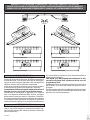
Dimensions: ....................................................................................................................See g.1
* Special supply voltages on request.
In case the motor tours in the opposite side, you should invert the running buckle
“M” of the operator. Refer to the relevant instruction manual for connection of
the control panel.
4) OPERATOR INSTALLATION
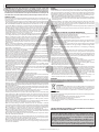
WARNING! Refer to Fig.A for CORRECT installation.
4.1) Preliminary checks
Check that:
• Thegatestructureissucientlysturdyandrigid.
The xing position must be worked out according to the leaf structure. In any
case, the manoeuvring arm must push against a reinforced leaf point (g. 2).
• Theleavescanbemovedmanuallyalongtheirentirestroke.
If the gate has not been installed recently, check the wear condition of all its
components. Repair or replace defective and worn parts.
Operator reliability and safety are directly aected by the condition of the
gate structure.
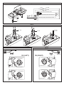
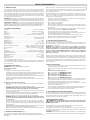
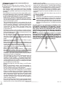
4.2) Fitting of the manual release knob
• Withreferencetog.9,positionreleaseknob“A”onange“B”prettedon
the cover.
• Insertadaptingring“C”inthebushwithreleasetooth“D”.
WARNING: Depending on the operator installation position (right or left
side), insert ring “C” and position bush “D” as shown in g. 9.
• Insertspacewasher“E”andthenshimmingthrustbearing“F”intobush”D”
on the release tooth side.
• Secureeverything,usingappropriateself-tappingscrew“G”insidetheoperator
cover, checking the correct positioning of ring “C” and bush “D”.
• Closetheoperatorcover,usingtheappropriatescrewssupplied.
WARNING: The release tooth on bush “D” must be inserted in the release
lever as shown in g. 9b. Otherwise, the emergency manoeuvre cannot
be carried out.
Insertion is made easy by turning knob “A” to the side opposite to that for
manual release (clockwise in the case of a left-hand leaf, anticlockwise in
the case of a right-hand leaf) and locking it in such position by means of the
appropriate key.
Check that bush “D” is placed horizontally (g. 9b) and close the cover by positioning
its front side (the one with the release knob) as indicated in g. 9c.
• Beforeconnectingtheoperatortothepowersupply,manuallycheckthat
the release knob operates correctly.
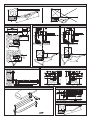
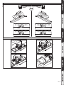
5) FIXING OF SUPPORTING PLATE (Fig.2)
The controller is supplied complete with anchoring bracket and lever arm.
Once the reinforcement point of the leaf has been identied with the gate closed,
draw an imaginary horizontal line from the centre of the reinforcement point
to the gate post (g.2). Position the anchoring bracket according to the values
given in g. 2 for openings of up to 90° or in g.3 for openings greater than 90°
up to a maximum of 125°.
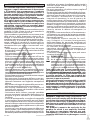
Thebracketxingpositionmustbeatandparalleltotheleaf.Usescrewsor
expansion bolts which are suited to the type of gate post. If the surface of the
gate post is not regular, use expansion bolts with studs so that the parallel plate
of the leaf can be adjusted (g.4).
• Fastenthegearmotortothegatepostusingthe4screws,pointingthege-
armotor to the left or the right (g.5).
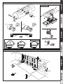
• Assembletheleverarmasshowning.6.
DX= assembly on the right leaf
SX= assemby on the left leaf
Choose the most suitable position of ‘F’ bracket for the fastening to the leaf.
• Insertthesquareoftherstleverintheoutputshaftofthegearmotorand
fasten it (g.7).
• Releasetheoperatorbyturningthereleaseknobtoalloweasymovementof
the arm (see paragraph on “EMERGENCY MANOEUVRE”).
• Thecorrectpositionforthecontrollerarmisshowning.8.
The leaf xing point can be identied by positioning the arm so that it is in
accordance with the distance shown in g.8.
• Fixtheangulartowingbar“F”totheleafbyweldingorusingscrews.
• Withthecontrollerreleased,checkthecorrectmovementofthearm.
• Repeatthesameoperationfortheotherleaf,ifinstalled.
6) ELECTRICAL INSTALLATION SET-UP
Arrange the electrical installation as shown in g.10.
The power supply connections must be kept separate from the auxiliary con-
nections (photocells, sensitive edge, etc.). Fig.10 shows the cross-section and
the number of connections.
WARNING! For connection to the mains, use a multipolar cable with a
minimum of 4x1.5mm
2
cross section and complying with the previously
mentioned regulations. For example, if the cable is out side (in the open), it
has to be at least equal to H07RN-F, but if it is on the inside (or outside but
placed in a plastic cable cannel) it has to be or at least egual to H05VV-F
with section 4x1.5mm
2
.
In g.11 you will nd the junction-box of the operator and the position of the
cable holder which should be xed with an adequate tightening of the bolt. In
case the motor tours in the opposite side, you should invert the running buckle
“M” of the operator. Refer to the relevant instruction manual for connection of
the control panel. Inside the operator the cable must be kept far from those parts
which can be hot.
7) LIMIT-SWITCH SETTING
• Positionthelimit-switchreferencecams“R-FC1”and“R-FC2”asshowning.
12, without tightening the xing screws.
• Identifytheopeningandclosinglimitswitches(FC1andFC2)keepinginmind
that:
In the left-hand operator (g. 13):
FC1 corresponds to the OPENING limit switch
FC2 corresponds to the CLOSING limit switch
In the right-hand operator (g. 14):
FC1 corresponds to the CLOSING limit switch
FC2 corresponds to the OPENING limit switch
• Whenthegateisfullyclosedoropened,rotatethecorrespondingcamuntil
you perceive the click of the limit microswitch concerned, and lock it in po-
sition by tightening the appropriate screws as shown in g. 12.
• Checkthatthelimitswitchesintervenecorrectly,initiatingafewcomplete
motor-driven opening and closing cycles.
• Fitthecoverontheoperator.
• fthecontrolpanelisprovidedwithoperation-timesetting,thismustbeset
to a value slightly greater than that needed for limit-switch intervention.
• ControltheoperatorthroughthecontrolboardLibra.
8) ADJUSTMENT OF LEAF PHASE DISPLACEMENT
In case of gates with two leaves, the control panel should include a delay setting
function on closing of the second leaf to guarantee a correct closing manoeuvre.
For the wiring of the motor which should close with a slight delay, refer to the
instructions for the control panel installed.
9) MOTOR TORQUE ADJUSTMENT
WARNING: Check that the impact force value measured at the points
established by the EN 12445 standard is lower than that specied in
the EN 12453 standard.
The adjustment of the motor torque (anti-squashing) is performed on the
control panel. See control unit instruction manual.
The adjustment should be set for the minimum force required to carry out the
opening and closing strokes completely observing, however, the limits of the
relevant standards in force.
CAUTION! Excessive torque adjustment may jeopardise the anti-squash safety
function.Ontheotherhandinsucienttorqueadjustmentmaynotguarantee
10 - IGEA
D811296_09

ENGLISH
correct opening or closing strokes.
10) EMERGENCY MANOEUVRE (Fig. 15)
In the case of power failure or operation malfunctions, manual emergency mano-
euvre can be carried out by turning the external release knob with personalised key.
First turn the key clockwise, then rotate the release knob to free the gate.
The knob is to be rotated anticlockwise in the case of a left-hand leaf, clockwise
in the case of a right-hand leaf.
Keep the knob in its release position by turning the key further. Push the leaf
slowly to open or close the gate.
To reactivate motor-driven operation, free the knob from its release position and
bring it back to its initial position for normal operation.
11) AUTOMATION CHECK
Before allowing the automation to be used normally, carry out the following
procedure very carefully:
• Checkthecorrectfunctioningofall safetydevices(limit microswitches,
photocells, sensitive edges etc.).
• Checkthatthethrust(anti-squash)forceoftheleafiswithinthelimitssetby
current regulations.
• Checkthemanualopeningcommand.
• Checktheopeningandclosingoperationswiththecontroldevicesinuse.
• Checkthestandardandcustomisedelectronicfunctioninglogic.
12) AUTOMATION OPERATION
Since the automation can be remote-controlled by means of a remote control
device or a start button, and so out of sight, the good working order
of all the safety devices should be checked regularly. In the event of any
anomalous functioning of the safety devices, consult a specialised technician
immediately. Keep children at a safe distance from the automation operation area.
13) CONTROL
The automation is used for the power-operated opening and closing of the
gate. The control can be of a number of types (manual, remote-controlled,
magnetic badge access control, etc.) depending on requirements and the
characteristics of the installation. See the specic instructions for the various
control systems. Users of the automation must be instructed about
its control and operation.
14) MAINTENANCE
Disconnect the power supply when carrying out any maintenance operations.
• LubricatetheIGEAs of the manoeuvring arm regularly.
• Cleanthelensesofthephotocellseverysooften.
• Haveaspecialisedtechnician(installer)checktheadjustmentoftheelectric
clutch.
• Intheeventofanyanomalousfunctioningwhichcannotberesolved,discon-
nect the power supply and contact a specialised technician (installer). Whilst
the automation is out of order, activate the manual release to allow manual
opening and closing.
INSTALLATION MANUAL
IGEA - 11
D811296_09

MANUALE D’USO: ( I )
2) MANOVRA DI EMERGENZA (Fig.1)
In caso di assenza di tensione di rete o anomalie di
funzionamento, la manovra manuale di emergen-
za può essere eseguita agendo sulla manopola di
sblocco esterna con chiave personalizzata.
Dopo aver ruotato la chiave in senso orario ruotare
la manopola di sblocco per liberare il cancello.
La rotazione della manopola è antioraria nel caso
di anta sinistra, oraria nel caso di anta destra.
Mantenere la manopola in posizione di sblocco
con una ulteriore rotazione della chiave. Spingere
lentamente l’anta per aprire o chiudere il cancello.
Per riattivare il funzionamento motorizzato, liberare
la manopola dalla posizione di sblocco e riportarla
nella posizione iniziale di normale funzionamento.
USER GUIDE: (GB )
In the case of power failure or operation malfun-
ctions, manual emergency manoeuvre can be car-
ried out by turning the external release knob with
personalised key.
Fig. 1
1
LEFT
RIGHT
1
2
3 3
2
First turn the key clockwise, then rotate the release
knob to free the gate.
The knob is to be rotated anticlockwise in the
case of a left-hand leaf, clockwise in the case of
a right-hand leaf.
Keep the knob in its release position by turning the
key further. Push the leaf slowly to open or close
the gate.
To reactivate motor-driven operation, free the knob
from its release position and bring it back to its initial
position for normal operation.
MANUALE D’USO: MANOVRA DI EMERGENZA / USER GUIDE:EMERGENCY OPERATION-
MANUEL D’UTILISATION: DE LA MANŒUVRE D’URGENCE
/ BEDIENUNGSHANDBUCH: NOTFALLMANÖVER-
MANUAL DE USO: MANIOBRA DE EMERGENCIA / MANUAL DE USO-MANOBRA DE EMERGÊNCIA
24 - IGEA
D811296_09

AVVERTENZE PER L’UTILIZZATORE ( I )
ATTENZIONE! Importanti istruzioni di sicurezza.
Leggere e seguire attentamente le Avvertenze
e le Istruzioni che accompagnano il prodotto
poiché un uso improprio può causare danni a
persone, animali o cose. Conservare le istruzioni
per consultazioni future e trasmetterle ad even-
tuali subentranti nell’uso dell’impianto.
Questo prodotto dovrà essere destinato solo
all’uso per il quale è stato espressamente insta-
llato. Ogni altro uso è da considerarsi improprio
e quindi pericoloso. Il costruttore non può essere
considerato responsabile per eventuali danni
causati da usi impropri, erronei e irragionevoli.
SICUREZZA GENERALE
Nel ringraziarVi per la preferenza accordata a questo
prodotto, la Ditta è certa che da esso otterrete le
prestazioni necessarie al Vostro uso.
Questoprodottorispondeallenormericonosciute
della tecnica e della disposizioni relative alla si-
curezza se correttamente installato da personale
qualicato ed esperto (installatore professionale).
L’automazione, se installata ed utilizzata corretta-
mente, soddisfa gli standard di sicurezza nell’uso.
Tuttavia è opportuno osservare alcune regole di
comportamento per evitare inconvenienti acci-
dentali:
- Tenere bambini, persone e cose fuori dal raggio
d’azione dell’automazione, in particolare durante
il movimento.
- Non permettere a bambini di giocare o sostare nel
raggio di azione dell’automazione.
-Questa automazione non è destinata all’uso da
parte di bambini o da parte di persone con ridotte
capacità mentali, siche e sensoriali, o persone che
mancano di conoscenze adeguate a meno che
esse non abbiano potuto beneciare, attraverso
l’intermediazione di una persona responsabile della
loro sicurezza, di una sorveglianza o di istruzioni
riguardanti l’uso dell’apparecchio.
- I bambini devono essere sorvegliati per sincerarsi
che non giochino con l’apparecchio. Non permet-
tere ai bambini di giocare con i controlli ssi. Tenere
i telecomandi lontani dai bambini.
-
Evitare di operare in prossimità delle cerniere o organi
meccanici in movimento.
-
Non contrastare il movimento dell’anta e non ten-
tare di aprire manualmente la porta se non è stato
sbloccato l’attuatore con l’apposita manopola di
sblocco.
-
Non entrare nel raggio di azione della porta o can-
cello motorizzati durante il loro movimento.
- Non lasciare radiocomandi o altri dispositivi di
comando alla portata dei bambini onde evitare
azionamenti involontari.
- L’attivazione dello sblocco manuale potrebbe
causare movimenti incontrollati della porta se in
presenza di guasti meccanici o di condizioni di
squilibrio.
- In caso di apritapparelle: sorvegliare la tapparella
in movimento e tenere lontano le persone nché
non è completamente chiusa. Porre cura quando si
aziona lo sblocco se presente, poiché una tapparella
aperta potrebbe cadere rapidamente in presenza
di usura o rotture.
-
La rottura o l’usura di organi meccanici della porta
(parte guidata), quali ad esempio cavi, molle, sup-
porti, cardini, guide.. potrebbe generare pericoli. Far
controllare periodicamente l’impianto da personale
qualicato ed esperto (installatore professionale)
secondo quanto indicato dall’installatore o dal
costruttore della porta.
- Per ogni operazione di pulizia esterna, togliere
l’alimentazione di rete.
- Tenere pulite le ottiche delle fotocellule ed i dispo-
sitivi di segnalazione luminosa. Controllare che rami
ed arbusti non disturbino i dispositivi di sicurezza.
- Non utilizzare l’automatismo se necessita di
interventi di riparazione. In caso di guasto o di
malfunzionamento dell’automazione, togliere
l’alimentazione di rete sull’automazione, astenersi
da qualsiasi tentativo di riparazione o intervento
diretto e rivolgersi solo a personale qualicato ed
esperto (installatore professionale) per la neces-
saria riparazione o manutenzione. Per consentire
l’accesso, attivare lo sblocco di emergenza (se
presente).
-
Per qualsiasi intervento diretto sull’automazione o
sull’impianto non previsto dal presente manuale,
avvalersi di personale qualicato ed esperto (insta-
llatore professionale).
- Con frequenza almeno annuale far verifi-
care l’integrità e il corretto funzionamento
dell’automazione da personale qualificato ed
esperto (installatore professionale), in particolare
di tutti i dispositivi di sicurezza.
- Gli interventi d’installazione, manutenzione e
riparazione devono essere documentati e la
relativa documentazione tenuta a disposizione
dell’utilizzatore.
- Il mancato rispetto di quanto sopra può creare
situazioni di pericolo.
DEMOLIZIONE
L’eliminazione dei materiali va fatta rispettan-
do le norme vigenti. Non gettate il vostro
apparecchio scartato, le pile o le batterie usate
nei riuti domestici. Avete la responsabilità di
restituire tutti i vostri riuti da apparecchia-
ture elettriche o elettroniche lasciandoli in
un punto di raccolta dedicato al loro riciclo.
Tutto quello che non è espressamente previs-
to nel manuale d’uso, non è permesso. ll buon
funzionamento dell’operatore è garantito solo
se vengono rispettate le prescrizioni riportate
in questo manuale. La Ditta non risponde dei
danni causati dall’inosservanza delle indicazioni
riportate in questo manuale.
Lasciando inalterate le caratteristiche essenziali
del prodotto, la Ditta si riserva di apportare in
qualunque momento le modiche che essa ritie-
ne convenienti per migliorare tecnicamente, cos-
truttivamente e commercialmente il prodotto,
senza impegnarsi ad aggiornare la presente
pubblicazione.
USER WARNINGS (GB)
WARNING! Important safety instructions. Ca-
refully read and comply with the Warnings and
Instructions that come with the product as impro-
per use can cause injury to people and animals
and damage to property. Keep the instructions
for future reference and hand them on to any
new users.
This product is meant to be used only for the
purpose for which it was explicitly installed.
Any other use constitutes improper use and,
consequently, is hazardous. The manufacturer
cannot be held liable for any damage as a result
AVVERTENZE PER L’UTILIZZATORE D811767_05
26 - IGEA
D811296_09

of improper, incorrect or unreasonable use.
GENERAL SAFETY
Thank you for choosing this product. The Firm is
condent that its performance will meet your ope-
rating needs.
This product meets recognized technical standards
and complies with safety provisions when installed
correctly by qualied, expert personnel (professional
installer).
If installed and used correctly, the automated system
will meet operating safety standards. Nonetheless,
it is advisable to observe certain rules of behaviour
so that accidental problems can be avoided:
- Keep adults, children and property out of range of
the automated system, especially while it is moving.
- Do not allow children to play or stand within range
of the automated system.
- This automated system is not meant for use by
children or by people with impaired mental, phy-
sical or sensory capacities, or people who do not
have suitable knowledge, unless a person who is
responsible for their safety provides them with
necessary supervision or instructions on how to
use the device.
- Children must be supervised to ensure they do not
play with the device. Do not allow children to play
with the xed controls. Keep remote controls out
of reach of children.
-
Do not work near hinges or moving mechanical parts.
- Do not hinder the leaf’s movement and do not
attempt to open the door manually unless the ac-
tuator has been released with the relevant release
knob.
- Keep out of range of the motorized door or gate
while they are moving.
- Keep remote controls or other control devices out
of reach of children in order to avoid the automated
system being operated inadvertently.
- The manual release’s activation could result in un-
controlled door movements if there are mechanical
faults or loss of balance.
- When using roller shutter openers: keep an eye
on the roller shutter while it is moving and keep
people away until it has closed completely. Exercise
care when activating the release, if such a device
is tted, as an open shutter could drop quickly in
the event of wear or breakage.
- The breakage or wear of any mechanical parts of
the door (operated part), such as cables, springs,
supports, hinges, guides…, may generate a hazard.
Have the system checked by qualied, expert per-
sonnel (professional installer) at regular intervals
according to the instructions issued by the installer
or manufacturer of the door.
- When cleaning the outside, always cut o mains
power.
- Keep the photocells’ optics and illuminating in-
dicator devices clean. Check that no branches or
shrubs interfere with the safety devices.
- Do not use the automated system if it is in need of
repair. In the event the automated system breaks
down or malfunctions, cut o mains power to the
system; do not attempt to repair or perform any
other work to rectify the fault yourself and instead
call in qualied, expert personnel (professional
installer) to perform the necessary repairs or main-
tenance. To allow access, activate the emergency
release (where tted).
- If any part of the automated system requires direct
work of any kind that is not contemplated herein,
employ the services of qualied, expert personnel
(professional installer).
- At least once a year, have the automated system, and
especially all safety devices, checked by qualied,
expert personnel (professional installer) to make
sure that it is undamaged and working properly.
- A record must be made of any installation, main-
tenance and repair work and the relevant docu-
mentation kept and made available to the user on
request.
- Failure to comply with the above may result in
hazardous situations.
SCRAPPING
Materials must be disposed of in accordance
with the regulations in force. Do not throw
away your discarded equipment or used bat-
teries with household waste. You are respon-
sible for taking all your waste electrical and
electronic equipment to a suitable recycling
centre.
Anything that is not explicitly provided for in the
user guide is not allowed. The operator’s proper
operation can only be guaranteed if the instruc-
tions given herein are complied with. The Firm
shall not be answerable for damage caused by
failure to comply with the instructions featured
herein.
While we will not alter the product’s essential
features, the Firm reserves the right, at any time,
to make those changes deemed opportune to
improve the product from a technical, design or
commercial point of view, and will not be required
to update this publication accordingly.
AVVERTENZE PER L’UTILIZZATORE D811767_05
IGEA - 27
D811296_09

Bft Spa
Via Lago di Vico, 44
36015 Schio (VI)
T +39 0445 69 65 11
F +39 0445 69 65 22
www.bft.it
SPAIN
BFT GROUP ITALIBERICA DE
AUTOMATISMOS S.L.
08401 Granollers - (Barcelona)
www.bftautomatismos.com
FRANCE
AUTOMATISMES BFT FRANCE
69800 Saint Priest
www.bft-france.com
GERMANY
BFT TORANTRIEBSSYSTEME Gmb H
90522 Oberasbach
www.bft-torantriebe.de
UNITED KINGDOM
BFT AUTOMATION UK LTD
Stockport, Cheshire, SK7 5DA
www.bft.co.uk
IRELAND
BFT AUTOMATION LTD
Dublin 12
BENELUX
BFT BENELUX SA
1400 Nivelles
www.bftbenelux.be
POLAND
BFT POLSKA SP. Z O.O.
05-091 ZąBKI
www.bft.pl
CROATIA
BFT ADRIA D.O.O.
51218 Drazice (Rijeka)
www.bft.hr
PORTUGAL
BFT SA-COMERCIO DE
AUTOMATISMOS E MATERIAL DE
SEGURANCIA
3020-305 Coimbra
www.bftportugal.com
CZECH REPUBLIC
BFT CZ S.R.O.
Praha
www.bft.it
TURKEY
BFT OTOMATIK KAPI SISTEMELERI
SANAY VE
Istanbul
www.bftotomasyon.com.tr
RUSSIA
BFT RUSSIA
111020 Moscow
www.bftrus.ru
AUSTRALIA
BFT AUTOMATION AUSTRALIA
PTY LTD
Wetherill Park (Sydney)
www.bftaustralia.com.au
U.S.A.
BFT USA
Boca Raton
www.bft-usa.com
CHINA
BFT CHINA
Shanghai 200072
www.bft-china.cn
UAE
BFT Middle East FZCO
Dubai
-
 1
1
-
 2
2
-
 3
3
-
 4
4
-
 5
5
-
 6
6
-
 7
7
-
 8
8
-
 9
9
-
 10
10
-
 11
11
-
 12
12


in altre lingue
- English: BFT Igea User manual
Documenti correlati
-
BFT Igea Manuale utente
-
-
-
-
-
-
-
-
-