
Before commissioning the machine, read operating
instructions and observe warnings and safety instructions.
Operating Instructions No. 998 742-A 12.07
4189
&
1000 531
Honda engine
Power HoePower Hoe
Power HoePower Hoe
Power Hoe
10001000
10001000
1000
OperatingOperating
OperatingOperating
Operating
InstructionsInstructions
InstructionsInstructions
Instructions

2 Power Hoe 1000
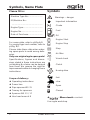
Symbols, Name Plate
Please fill in:
Machine Type No.:......................
ID/Machine No.:
...................................................
Engine Type:...............................
Engine No.:.................................
Date of Purchase: ......................
For name plate, refer to p3/fig.A/8.
For engine type and number, refer to
p3/fig. B/7.
Please state these data when order-
ing spare parts to avoid wrong deliv-
eries.
Only use original agria spare parts!
Specifications, figures and dimen-
sions stated in these instructions are
not binding. No claims can be derived
from them. We reserve the right for
improvements without changing these
instructions.
Scope of delivery:
l
Operating instructions
l
Power hoe
l
Pipe spanner WS 21
l
Tommy for spanners
l
Spanner WS 13 / 17
l
Hex head wrench 8
Symbols
Warnings – danger
Important information
Choke
Fuel
Oil
Engine Start
Engine Stop
Stop
Air filter
Visual check
Clutch
Hoeing drive
fast
slow
Open
Closed
è
- Serviceç= contact
Your agria workshop

Power Hoe 1000 3
Part Designations
A
B

4 Power Hoe 1000
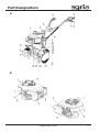
Part Designations
Fig. A
1 Engine
2 Push plate for lateral handlebar adjustment
3 Steering handle
4 Speed control lever, engine shut-off switch
5 Safety circuit lever
6 Clutch lever
7 Pawl of clutch lever
8 Factory type plate
9 Steering handle height adjusting clamping lever (on the right side)
10 Clutch cable
11 Clutch cable setting screw on gearbox housing
12 R-clip on depth bar
13 Hoeing guard
14 Depth bar
15 Handle
16 Base specification hoeing tools, right
17 Receiving hole for front wheel attachment
18 Transmission oil fill/drain opening
19 Base specification hoeing tools, left
20 Attachment bolt for base specification tools
21 Guard disc
Fig. B
1 Fuel tank cap
2 Starter rope handle
3 Air strainer
4 Oil fill plug, dip-stick
5 Air filter
6 Carburetor / speed control governor
7 Engine type no. / identification no.
8 Spark plug / spark plug connector
9 Exhaust with guard
10 Fuel tank
11 Fuel tap

Power Hoe 1000 5
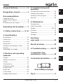
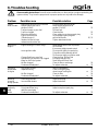
Index
3
5
6
7
2
1
4
Scope of delivery ...................2
Designation of parts ..............3
Recommendations
Lubricants and
anticorrosive agents........................ 6
Fuel ................................................. 6
Maintenance and repair.................. 6
Unpacking and assembly....... 7
1. Safety instructions.......8–12
2. Specifications
Dimensions ................................... 14
Power hoe ..................................... 14
Hoe drive....................................... 14
Noise level .................................... 14
Vibration acceleration value ......... 14
Engine........................................... 15
Operability on slopes .................... 15
3. Machine and operating
elements
Engine........................................... 16
Safety circuit lever......................... 17
Clutch............................................ 17
Transmission ................................. 17
Steering handle ............................ 18
Hoeing tools.................................. 19
Depth bar ...................................... 20
Front wheel ................................... 20
Ridging attachment....................... 21
4. Commissioning and
operation
Commissioning the machine ........ 22
Starting the engine ....................... 23
Shutting off the engine ................. 24
Hoeing........................................... 25
5. Maintenance
Transmission ................................. 26
Clutch free play ............................. 27
Engine..................................... 28–31
General ......................................... 33
Cleaning........................................ 33
Storage ......................................... 34
Varnishes,
wear parts .............................35
Electrical wiring ...................35
6. Troubleshooting..........36–37
7. Inspection and
maintenance chart ............... 38
Conformity declaration........39
Note folding-out page!
Fig. A ....................................... 3

6 Power Hoe 1000
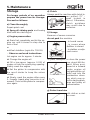
Recommendations
Do not add oil to petrol.
If, for environmental reasons, you use
unleaded petrol, make sure the fuel is
drained completely when shutting down
the engine for more than 30 days. This
is to prevent resin residue from deposit-
ing in the carburetor, fuel filter, and tank.
Or add a fuel stabilizer to the fuel.
For further instructions refer to “Engine
Preservation”.
Maintenance and Repair
The trained mechanics of your agria
workshop expertly carry out any main-
tenance and repair work.
You should only carry out major mainte-
nance work and repairs on your own, if
you have the proper tools and knowl-
edge of machines and internal combus-
tion engines.
Do not hammer against the flywheel with
a hard object or metal tools as it might
crack and shatter in operation, causing
injuries and damage. Only use suitable
tools to pull off the flywheel.
Lubricants and
Anti-Corrosive Agents
Use the lubricants specified for engine
and gearbox (see “Specifications”).
We recommend using Bio-lubricating
oil or Bio-lubricating grease for “open”
lubrication points or nipples (as speci-
fied in the operating instructions).
We recommend using Bio-slushing oil
to preserve machines and attachments
(do not apply on painted covers). You
can brush or spray the oil.
Anti-corrosive agents are environmen-
tally friendly and degrade fast.
Using ecologically safe Bio-lubricants
and Bio-anti-corrosives, you contribute
to environmental protection and to the
wellbeing of humans, animals and
plants.
Fuel
This engine runs smoothly on conven-
tional unleaded regular and super-
grade petrol as well as on leaded
supergrade petrol.

Power Hoe 1000 7
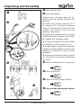
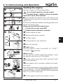
Unpacking and Assembly
Open the box top.
Mount handlebar
Remove the clamping lever (4) to-
gether with the washer (3) from the
machine.
l
Attach the steering handle (1) to
its bearing (2), using the clamping
lever (4) and washer (3) (ensure that
cables and electric lines are not
twisted or jammed).
l
Adjust the handlebars to working
height and lock the gears into mesh.
l
Tighten the clamping lever.
l
Connect the electric line (for safety
circuit lever) to the socket (5 + 6).
l
Inspect again whether all Bowden
cables are routed properly and are not
twisted or jammed to avoid clutch
problems.
l
Remove the machine from the box
or cut it open in 4 corners to fold down
the sides.
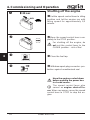
Attach all hoeing tools and guards
Attach depth bar
Attach the rear support wheel
Carry out the start-up procedure
19
20
22
20

8 Power Hoe 1000
1. Safety Instructions
1
Before starting the machine, read the
operating instructions and note:
Warning
This symbol marks all paragraphs in
these operating instructions which affect
your safety. Pass all safety instructions
on to other users and operators.
Due Use
The power hoe and the mounted imple-
ments authorized by the manufacturer
have been designed for all common
applications and tasks in farming and
forestry, horticulture and park mainte-
nance (due use).
Any other type of operation is consid-
ered undue. The manufacturer is not li-
able for any damages resulting from
undue use, for which the risk lies with
the user alone.
Due use includes compliance with
manufacturer’s instructions on opera-
tion, maintenance and repair.
Any unauthorized changes to the power
hoe render manufacturer liability null and
void.
General Instructions on
Safety and Accident
Prevention
Basic Rule:
The respective national accident preven-
tion regulations have to be adhered to,
as well as all other generally accepted
rules governing operational safety, oc-
cupational health and road traffic regu-
lations.
When driving on public roads, you have
to observe the current traffic code.
Accordingly, check the power hoe for
road and operational safety each time
you take up operation.
Only persons familiar with the machine
and instructed on the hazards of opera-
tion are allowed to use, maintain and
repair the machine.
Teenagers younger than 16 years are
not allowed to operate the power hoe!
Only work in good light and visibility.
Operator’s clothes should fit tight. Avoid
wearing loose fitting clothes. Wear solid
shoes.
Note the warning and instruction signs
on the machine for safe operation. Com-
ply for your own safety.
When transporting the power hoe on
vehicles or trailers outside the area to
be cultivated, ensure that the engine is
shut off.
Careful with rotating tools – keep at a
safe distance!

Power Hoe 1000 9
1. Safety Instructions
1
Beware of coasting tools. Before you
start any maintenance or repair on them,
wait until tools have come to a complete
stop.
Riding on the machine during operation
is not permitted.
Mounted or trailed attachments and
loads/weights affect the machine’s driv-
ing, steering, braking, and tipping char-
acteristics. Therefore, ensure that steer-
ing and braking functions are sufficient.
Match operating speed to conditions.
Do not change settings of governor. High
engine speed increases risk of acci-
dents.
Working Area and Danger
Zone
The user is liable to third parties work-
ing within the machine’s working range.
Staying in the danger zone is not per-
mitted.
Check the immediate surroundings of
the machine before you start it. Watch
out for children and animals.
Before you start work, clear the area
from any foreign object. During opera-
tion, always watch out for further objects
and remove them in time.
For operation in enclosed areas, ensure
that a safety distance is kept to enclo-
sures to prevent damage to tools.
Operation and Safety
Devices
Before you start the engine
Become familiar with the devices and
operating elements and their functions.
Above all, learn how to shut off the en-
gine quickly and safely in an emergency.
Ensure that all protective devices are
mounted and positioned to provide pro-
tection.
Starting the engine
Do not start engine in closed rooms. The
carbon monoxide contained in the ex-
haust fume is extremely toxic when in-
haled.
When starting the engine, do not step
in front of the power hoe and the attach-
ment.
Operation
Never leave the operator’s position at
the steering handle while the power hoe
is at work.
Never adjust the handles during work –
danger!
During operation keep a distance to the
machine as defined by the length of the
steering handle, especially when you
turn the machine.
Riding on the machine during operation
or in transport is not permitted.
In case of blockages in the attachment,
shut off the engine and clean the attach-
ment with an appropriate tool.
In case of damage to the power hoe or
to the attachment, immediately shut off
the engine and have it repaired.

10 Power Hoe 1000
1. Safety Instructions
1
If steering causes problems, immedi-
ately bring the power hoe to a halt and
shut it off. Have the malfunction repaired
without delay.
To prevent the machine from slipping on
slopes make sure it is secured by an-
other person using a bar or a rope. This
person must be located at a higher po-
sition than the vehicle at a safe distance
from the attachment at work.
If possible, always work at right angle
to the slope.
End of Operation
Never leave the power hoe unattended
with the engine running.
Before you leave the power hoe, shut
off the engine. Then close fuel taps (if
equipped).
Secure power hoe against unauthorized
use. If the machine is equipped with an
ignition key, remove the key. For all other
versions, remove the spark plug connec-
tor.
Attachments
Only mount attachments with the engine
and the attachment drive shut off.
Always use appropriate tools and wear
gloves when changing attachments and
parts thereof.
For mounting and dismounting attach-
ments bring the support devices into
proper position and ensure stability.
Secure the power hoe and attachments
against rolling off (parking brake, wheel
chocks).
Beware of injuries while coupling attach-
ments.
Hitch attachments as specified and only
couple at specified points.
Secure power hoe and attachment
against unauthorized use and rolling off
when you leave the machine. If neces-
sary, install transport or protective de-
vices and secure.
Hoeing
When hoeing, make sure the depth bar
is adjusted properly.
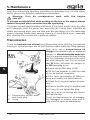
Maintenance
Do not maintain or clean the machine
while the engine is running.
Before you work on the engine, always
remove the spark plug connector.
Check regularly and, if necessary, re-
place all protecting devices and tools
subject to wear and tear.
Replace damaged cutting tools.
Always wear safety gloves and use
proper tools when exchanging cutting
tools.
Do not carry out repairs like welding,
grinding, drilling, etc. on structural and
safety-relevant parts (e.g. coupling de-
vices)!
Keep power hoe and attachment clean
to avoid risk of fire.

Power Hoe 1000 11
1. Safety Instructions
1
Check nuts and bolts regularly for tight
fit and re-tighten, if necessary.
Ensure that you re-install all safety and
protective devices and adjust them prop-
erly after maintenance and cleaning.
Only use original agria spare parts. All
other commercial spare parts must cor-
respond to quality and technical require-
ments specified by agria.
Storage
It is not allowed to store the power hoe
in rooms with open heating.
Never park the power hoe in closed
rooms with fuel left in tank. Fuel vapours
are hazardous.
Engine, Fuel, and Oil
Never let the engine run in closed rooms.
Extreme danger of intoxication! For the
same reason, also replace damaged
exhaust pipes immediately.
Be careful when dealing with fuel. Great
danger of fire! Never refill fuel close to
open fire, inflammable sparks or hot
engine parts. Do not refill fuel in closed
rooms. Do not smoke when refilling!
Refill only with the engine shut off and
cooled down.
Do not spill any fuel, use a proper filling
device.
In case of fuel-spillage, pull the power
hoe away from the spillage before you
start the engine.
Make sure fuel is of specified quality.
Store fuel in approved cans only.
Liquids leaking under high pressure, e.g.
fuel, can penetrate the skin and cause
severe injuries. Immediately see a doc-
tor.
Store anti-corrosive agents and stabi-
lizing liquids out of reach of children. If
sickness and vomiting occur, see a doc-
tor immediately. If the fuel has contacted
eyes, rinse them thoroughly, avoid in-
haling of vapours.
Read and observe enclosed instruc-
tions.
Before you dispose of opened and
seemingly empty pressurised tins (e.g.
of assist-starting liquids) make sure they
are completely empty. Empty them in
ventilated places safe from spark forma-
tion or flames. If necessary, dispose of
tins in hazardous waste deposits.
Be careful when draining hot oil, dan-
ger of burns.
Make sure oil used is of specified qual-
ity. Storage is in approved cans only.
Dispose of oil, greases, and filters
seperately and properly.
Electrical System
Persons having a pacemaker may not
touch live parts of the ignition system
when the engine is running.

12 Power Hoe 1000
1. Safety Instructions
1
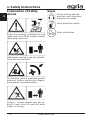
Explanation of Safety
decals
Before any cleaning, maintenance, and
repair work shut off the engine and pull
spark plug connector.
With engine running, keep at a safe dis-
tance from hoeing tools.
Do not work without protective guards
mounted. Before starting the engine,
bring guards in proper position.
Danger – foreign objects may get air-
borne. Keep clear off machine while
engine is running.
Signs
When working with the
machine, wear individual
protective ear plugs.
Wear protective gloves.
Wear solid shoes.

Power Hoe 1000 13
1

14 Power Hoe 1000
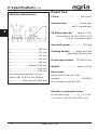
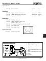
2. Specifications Hoe
2
Machine dimensions:
a ........................................ 340 mm
b ........................................ 570 mm
c......................................... 130 mm
d ........................................ 500 mm
e ........................................ 600 mm
h .......................... approx.1000 mm
l........................................ 1450 mm
A ........................................ 600 mm
All safety requirements in accor-
dance with CEN/GS are fulfilled:
k.................>900 mm at h=800 mm
Power hoe
Clutch:................................Ball clutch
Transmission:.................. Worm gear
with 1 forward gear
Oil filling capacity:...... approx. 0.25 l
Transmission oil SAE 90-API GL5
(e.g. BP Energear Hypo)
Hoe shaft speed: ..................130 rpm
Steering handle:........ height and side
adjustable without tools
Front support wheel... Ø 200x50 mm
Weight: ..........................approx. 44 kg
Noise level:
Noise level at the ear of the
operator ................................80 dB(A)
(in accordance with EN 709)
Vibration acceleration value:
at handlebar grip........... a
hw
= 5.7 m/s
2
in accordance with EN 709 and EN 1033

Power Hoe 1000 15
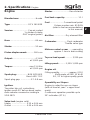
2. Specifications Engine
2
Engine
Manufacturer: ..........................Honda
Type: ............................ GCV 160 N2E
Version: ....................... Fan-air-cooled
1 cylinder-4-stroke
OHC engine (petrol)
Bore: ........................................ 64 mm
Stroke: ..................................... 50 mm
Piston displacement:...........160 ccm
Output: .................................... 4.1 kW
at 3,000 rpm
Torque: .......................... max 11.4 Nm
at 2,500 rpm
Spark plug: ................ NGK BPR 6ES
Bosch WR 7 DC
Spark plug gap: ............... 0.7–0.8 mm
Ignition:
Transistor trip coil, contactless;
ignition point: 20° before dead centre,
radio remote screened according to
VDE 0879
Valve lash (engine cold)
Intake: ........................0.15 ± 0.04 mm
Outlet: ........................0.20 ± 0.04 mm
Starter: ..........................Recoil starter
Fuel tank capacity: .................... 1.1 l
Fuel:..................... Conventional petrol
Octane number min. 85 RON
(refer to fuel recommendations
in this manual)
Air filter: ..................Dry element filter
Carburetor: ............... Float carburetor
Throttle valve type
Mixture control screw: .....opened by
approx. 1 turn in base setting
Top no-load speed: ...........3,250 rpm
Idling speed:...........1,550–1,850 rpm
Engine oil:
Filling quantity................approx. 0.55 l
Multi-grade oil SAE 10 W-40
S
G, SF or higher quality grade
Operability on Slopes:
Engine is suited for use on slopes
(with oil level at „max“ = upper level
mark)
Continuous operation possible up to
20° inclination (
37 %)

16 Power Hoe 1000
3. Machine and Operating Elements
C
3
The power hoe agria type 1000 is suited
for all usual applications in horticulture,
in agriculture and forestry as well as in
park maintenance.
Engine
The four-stroke petrol engine is operated
with commercial petrol (see fuel recom-
mendation on page 6). During the first
20 operating hours (break-in period), the
motor should not be operated at load
limit. Even after the break-in period,
you should make it a principle to never
push the accelerator more than is just
necessary for the actual work.
I
High engine speed is harm-
ful to any engine and con-
siderably affects its durability. This
applies especially for no load opera-
tion. Any overspeed (have the engine
roar) can result in immediate damage.
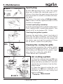
Cooling System
The engine is fan-cooled. Therefore
keep screen at recoil starter and cool-
ing fins of cylinder clean and free from
sucked-in plant trash.
Idling-speed
Always ensure that idling-speed is ad-
justed correcty. At low speeds and with
the speed control lever set to idle, the
engine is supposed to run smoothly and
without run-out.
Air Filter
The air filter purifies the air intake. A
clogged filter reduces engine output.
Ignition System
The engine is equipped with a mainte-
nance-free, contactless electronic igni-
tion system. We recommend to have
necessary check-ups done by an expert
only.
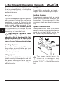
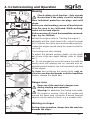
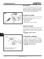
Speed Control Lever
The speed control lever (A/4) on the
steering handle serves to control engine
speed, to set the CHOKE and to stop
the engine. For positions see fig. C
I
The speed control lever also
serves as an emergency shut-
off. In an emergency, move the lever to
position “STOP” to shut off the engine
fast.

Power Hoe 1000 17
3. Machine and Operating Elements
3
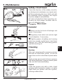
Safety circuit Lever
The power hoe is equipped with a safety circuit
lever.
Stop position: When releasing the lever (A/5),
the ignition system is shut off (engine is off).
Beware – engine keeps running due to centrifugal
mass.
Start position: For starting the engine and for
short breaks, pull the hand clutch lever (A/6) and
fasten with pawl.
Operating position: To operate the machine
press safety circuit lever.
W
Do not tie down safety circuit lever.
I
The speed control lever also serves as an
emergency shut-off. In an emergency, move
the lever to position “STOP”, the lever automatically
goes to STOP position.
Clutch
The power hoe is equipped with a ball clutch. This
is actuated using the clutch hand lever (A/6). Pull
the lever to disengage the gear and to stop the
engine driving the hoeing tools. When the lever is
opened (pawl A/7 is not locked) a positive connec-
tion between engine and tools is made and the
hoeing tools start operating. With the control lever
pulled, this connection is disengaged and the tools
come to a stop.
Transmission
The power hoe is equipped with a worm transmis-
sion with one forward gear.
3

18 Power Hoe 1000
3. Machine and Operating Elements
3
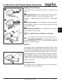
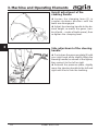
Height adjustment of the
steering handle
l
Loosen the clamping lever (1) in
counter-clockwise direction until the
teeth are disengaged.
l
Adjust the steering handle to the de-
sired height, re-match the gears (cen-
tre of tooth – centre of tooth space); then
re-tighten the clamping lever.
Side adjustment of the steering
handle
l
Push down the pressure plate (2) with
your right hand while slightly lifting the
steering handle (as shown in the figure);
then swing it to the left or right.
l
Release the pressure plate, slightly
move the steering handle to the left and
right until it locks into the toothing.
2

Power Hoe 1000 19
3. Machine and Operating Elements
3
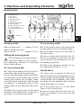
Hoeing tools
1 Hexagon nut
2 Linch pin
3 Star washer
4 Extension guard
5 Guard discs
6 Add-on hoeing tool
7 Hex head bolt
8 Base hoeing tool, right
9 Countersunk bolt
10 Base hoeing tool, left
Example: Hoeing width 70 cm
Example: Hoeing width 50 cm
S = Blade
Working width:
Base hoeing tools: ........approx. 50 cm
Base hoeing tools and
add-on tools: .................approx. 70 cm
Fitting the hoeing tools
W
Only fit/remove the hoeing tools
while the engine is shut off and
the spark-plug connector is removed!
Wear safety gloves!
50 cm working width:
l
Fit the base hoeing tools (8 and 10)
onto both ends of the hoeing shaft.
Ensure that the blades point into travel-
ling direction. When fitting the second
hoeing tool (either left or right), make
sure the knives pointing to the housing
are fitted in a staggered way to the
knives fitted on the opposite end of the
shaft.
l
Attach the hoeing tools to the shaft
using the hex head bolts (7) that go in
the holes on the hubs and shaft.
70 cm working width:
l
Fit the hoeing tools in the same way
as described in 50 cm working width.
l
Fit the add-on tools (6) in the hubs of
the base tools.
l
Secure them with the linch pin (2)
which is inserted in the holes on hub
and shaft (linch pin pointing in the con-
tra-rotating direction).
l
Attach the extension guards (4) us-
ing attachment bolts (9, 3 + 1).
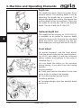
Guard discs
The discs are to prevent shrubs and
bushes from being damaged by the hoe
and to protect young plants from being
covered with soil. In addition, they offer
protection for the operator when hoeing
along field edges or fences.
l
Fit the guard discs (5) in the outer
hubs on the hoeing tools.
l
Secure them with the linch pin (2)
which is inserted in the holes on hub
and shaft.

20 Power Hoe 1000
3. Machine and Operating Elements
3
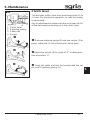
Depth bar
The depth bar slows down the power hoe’s
forward speed. The working depth is set by
adjusting the depth bar as required. The
deeper the depth bar setting, the deeper the
working depth of the hoeing tools. There are
two holes to set the bar (14) to the desired
depth. Secure it with the R-clip (12).
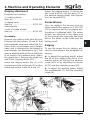
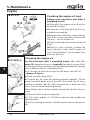
Optional depth bar
This depth bar (accessory no. 1001 511) (1)
is available as an option to improve depth
control in loose soils. Remove the standard
depth bar (A/14) and replace it by the op-
tional depth bar, locking it with the R-clip (2).
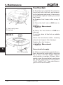
Front wheel
For easier transport, use the front wheel.
Push the wheel’s axle into the receiving bear-
ing (A/17) and attach it with the pressure
spring, washer and split pin in the order il-
lustrated (fig. I).
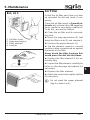
You can leave the wheel on the machine
during hoeing, if you pivot it up into hoeing
position.
Hoeing position:
l
Press your hand on the wheel’s axle (see
arrow in fig.) to unlock the bracket.
l
Pivot the bracket up and lock it.
Travelling position:
l
Correspondingly, pivot the bracket down
and lock it.
La pagina sta caricando ...
La pagina sta caricando ...
La pagina sta caricando ...
La pagina sta caricando ...
La pagina sta caricando ...
La pagina sta caricando ...
La pagina sta caricando ...
La pagina sta caricando ...
La pagina sta caricando ...
La pagina sta caricando ...
La pagina sta caricando ...
La pagina sta caricando ...
La pagina sta caricando ...
La pagina sta caricando ...
La pagina sta caricando ...
La pagina sta caricando ...
La pagina sta caricando ...
La pagina sta caricando ...
La pagina sta caricando ...
La pagina sta caricando ...
-
 1
1
-
 2
2
-
 3
3
-
 4
4
-
 5
5
-
 6
6
-
 7
7
-
 8
8
-
 9
9
-
 10
10
-
 11
11
-
 12
12
-
 13
13
-
 14
14
-
 15
15
-
 16
16
-
 17
17
-
 18
18
-
 19
19
-
 20
20
-
 21
21
-
 22
22
-
 23
23
-
 24
24
-
 25
25
-
 26
26
-
 27
27
-
 28
28
-
 29
29
-
 30
30
-
 31
31
-
 32
32
-
 33
33
-
 34
34
-
 35
35
-
 36
36
-
 37
37
-
 38
38
-
 39
39
-
 40
40


in altre lingue
- English: Agria 1000 Owner's manual
Documenti correlati
-
Agria 0100 Manuale del proprietario
-
-
Briggs & Stratton 0400 Manuale del proprietario
-
-
-
-
-
-
-