
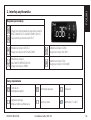
Installation Guide
ERC 214
Digital controller for refrigeration and defrost, 4 relays.

| 2 DKRCE.PI.RL0.H7.MLInstallation Guide | ERC 214
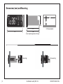
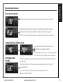
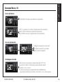
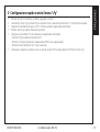
Dimensions (mm) and Mounting
83
66
Rear mounting (lock with clips)
Drilling template
Mounting Dismounting
61.2
28
D
36
71
29

| 3DKRCE.PI.RL0.H7.ML Installation Guide | ERC 214
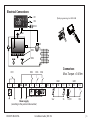
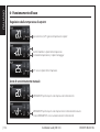
Electrical Connections
DO1
12
SairS5Sc/DI
1D
I2
DO2 DO3 DO4
GN
DG
ND
3L 4N 567891011121
31
4
~~~~
Sair
Sc
DI1
DI2
DO4
DO2
DO3
DO1
S5
Power supply
(according to the product code number)
Connectors:
Max. Torque = 0.4 Nm
Quick programming tool: EKA 183B

| 4 DKRCE.PI.RL0.H7.MLInstallation Guide | ERC 214
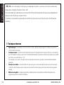
ENGLISH
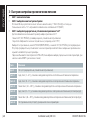
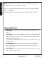
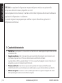
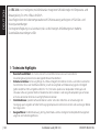
1 - Technical Highlights
y Ease of use: Four buttons, easy menu structure, pre-installed application solutions ensure superior usability.
y Simple installation:
High Effect 16 A relay enable direct connection of heavy loads without use of intermediate relay: up to 2 hp
compressors depending on its power factor and motor efficiency (greater than 0.65 for 230 V and greater than 0.85
for 115 V).
A wide range of compatible types of sensors and screw connection terminals ensure highly flexible installation.
y Unit protection: Special software features like compressor protection from fluctuation in the power supply or from
high condensing temperature ensure the safe operation of the unit.
y Energy efficiency: Defrost on demand, day/night mode and smart evaporator fan management ensure energy
efficiency.
The ERC 214 is a smart, multipurpose integrated refrigeration controller with temperature and defrost
management, available with 4 relays.
This controller is for Operating temperature sensing control, suitable for refrigeration and heating
applications.
Incorporated control has been designed to fulfil today’s requirements for commercial refrigeration
applications.

| 5DKRCE.PI.RL0.H7.ML Installation Guide | ERC 214
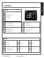
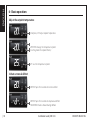
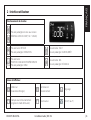
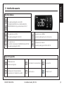
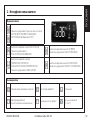
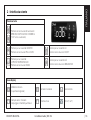
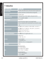
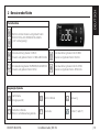
2 - User Interface
Press for one second: BACK
Press and hold: PULL-DOWN
Press for one second: UP
Press and hold: ON/OFF
Press for one second:
TEMPERATURE SETPOINT/OK
Press and hold: MENU
Press for one second: DOWN
Press and hold: DEFROST
Key Function
Press and hold at power up:
FACTORY RESET
(“FAC” is displayed)
Display Icons
Night mode
(Energy saving)
Fan running Defrost
Compressor running
Flashes in pull-down mode
Active alarm Unit (°C or °F)
ENGLISH

| 6 DKRCE.PI.RL0.H7.MLInstallation Guide | ERC 214
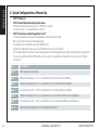
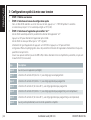
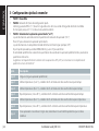
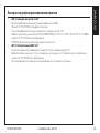
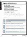
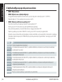
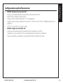
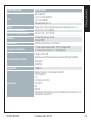
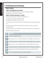
3 - Quick Configuration at Power Up
y STEP 1: Power on
y STEP 2: Select the quick configuration menu
Within 30 seconds of power on, press “<” BACK for 3 seconds.
The main switch “r12” is automatically set to OFF.
y STEP 3: Select pre-installed application “o61”
The display automatically shows the application selection parameter “o61”.
Press SET to select the pre-installed application.
The display shows the default value (eg. “AP0” flashing).
Choose the application type by pressing UP/DOWN and press SET to confirm.
The controller presets parameter values according to the selected application and does not hide relevant parameters.
Tip: you can easily move from AP0 to AP6, and thus select the simplified list of parameters, by pressing the UP key
(circular list).
App Description
App 0 None (no preset application)
App 1 Medium temperature (2 – 6 °C), ventilated ref. units with timed natural defrost
App 2 Medium temperature (0 – 4 °C), ventilated ref. units with timed electrical defrost
App 3 Low temperature (-26 – -20 °C), ventilated ref. units with timed electrical defrost
App 4 Medium temperature (0 – 4 °C), ventilated ref. units with electrical defrost (by temperature)
App 5 Low temperature (-26 – -20 °C), ventilated ref. units with electrical defrost (by temperature)
App 6 None (no preset application) with simplified parameter list
ENGLISH

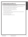
| 7DKRCE.PI.RL0.H7.ML Installation Guide | ERC 214
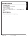
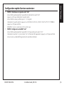
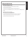
Quick Configuration at Power Up
y STEP 4: Select sensor type “o06”
The display automatically shows sensor selection parameter “o06”.
Press SET to select the sensor type.
The display shows the default value (eg. “n10” flashing).
Choose sensor type by pressing UP/DOWN (n5=NTC 5 K, n10=NTC 10 K, Ptc=PTC, Pt1=Pt1000) and press SET to
confirm.
NOTE: All sensors must be the same type.
y STEP 5: Configure DO4 output “o36”
The display automatically shows the “o36” parameter to configure “DO4” output.
Select light (“Lig”) or alarm (“ALA”) as per the application and press SET to confirm.
The display returns to normal display mode and the control is started.
ENGLISH

| 8 DKRCE.PI.RL0.H7.MLInstallation Guide | ERC 214
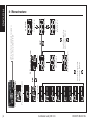
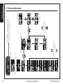
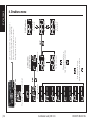
4 - Menu structure
1) Parameter groups
2) Parameter name
Scroll through the
parameter groups
SET: press for 3 seconds to access
status, setup and service
Password (if enabled)
Status input
Configuration
Main switch
Application
Sensor type
DO4 configuration
SET
Scroll through the
parameter names
SET
3) Value
Application 0
Application
6-5-4-3-2-1
Application
1-2-3-4-5-6
ENGLISH

| 9DKRCE.PI.RL0.H7.ML Installation Guide | ERC 214
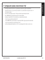
5 - Quick Configuration via “cFg” Menu
y Press SET for three seconds to access the parameters groups.
y Select “CFg” menu and press SET to enter. The first menu “r12” (main switch) is displayed.
y Switch OFF main switch (r12=0) for changing the pre-installed application.
y Press UP/DOWN to scroll through the parameter list.
y Configure the “o61” parameter to select a pre-installed application:
- Press SET to access the “o61” parameter.
- Press UP/DOWN to select an application (AP0= no application selected).
- Press SET to confirm, “o61” is displayed.
y Continue to set the next parameters (“o06” sensor type and “o36” DO4 configuration) in the “cFg” menu.
ENGLISH

| 10 DKRCE.PI.RL0.H7.MLInstallation Guide | ERC 214
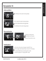
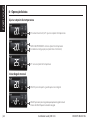
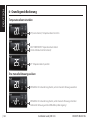
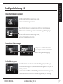
6 - Basic operation
Initiate a manual defrost
Adjust the setpoint temperature
DEFROST: press for 3 seconds to initiate a defsost.
The DEFROST icon is shown during defrost.
DEFROST: press for 3 seconds to stop manual defrost.
(short press) SET: adjust setpoint temperature.
UP/DOWN: change the temperature setpoint
(in setting mode the setpoint flashes).
SET: save the temperature setpoint.
ENGLISH

| 11DKRCE.PI.RL0.H7.ML Installation Guide | ERC 214
Initiate a pull down
PULL DOWN: press for 3 seconds to stop pull down.
PULL DOWN: press for 3 seconds to initiate pull down.
“Pud”: is shown for 3 seconds to indicate pull down.
The PULL DOWN icon flashes during pull down.
View an active alarm
Temperature and alarm codes
alternate flashes until the alarm
is resolved. The alarm bell is shown.
Unlock keyboard
- After 5 minutes of no activity, the keypad is locked (if P76=yes).
- When the keypad is locked any button press shows “LoC” in the display.
- Press UP and DOWN buttons simultaneously for 3 seconds
to unlock the keyboard. “unl” is displayed for 3 seconds.
Basic operation - 02
ENGLISH

| 12 DKRCE.PI.RL0.H7.MLInstallation Guide | ERC 214
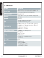
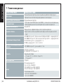
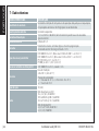
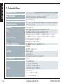
FEATURES DESCRIPTION
Purpose of control
Operating temperature sensing control suitable for incorporation into
commercial air-conditioning and refrigeration applications
Construction of control Incorporated control
Power supply
115 V AC / 230 V AC 50/60 Hz, galvanic isolated low voltage regulated
power supply
Rated power Less than 0.7 W
Inputs
Sensor inputs, Digital inputs, Programming key
Connected to SELV limited energy <15 W
Allowed sensors types
NTC 5000 Ohm at 25 °C, (Beta value=3980 at 25/100 °C - e.g. EKS 211)
NTC 10000 Ohm at 25 °C, (Beta value=3435 at 25/85 °C - e.g. EKS 221)
PTC 990 Ohm at 25 °C, (e.g. EKS 111)
Pt1000, (e.g. AKS 11, AKS 12, AKS 21)
Sensors included in Kit Solution NTC 10000 Ohm at 25 °C, cable length=1.5 m
Accuracy
Measuring range:
-40 – 105 °C (-40 – 221 °F)
Controller accuracy:
+/-1 K below -35 °C, +/-0.5 K between -35 – 25 °C,
+/-1 K above 25 °C
Type of action 1B (relay)
Output
DO1 Compressor relay:
16 A, 16 (16) A, EN 60730-1
10 FLA / 60 LRA @230 V, UL60730-1
16 FLA / 72 LRA @115 V, UL60730-1
7 - Technical Data
ENGLISH

| 13DKRCE.PI.RL0.H7.ML Installation Guide | ERC 214
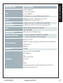
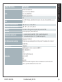
FEATURES DESCRIPTION
Output
DO2 Defrost relay:
8 A, 2 FLA / 12 LRA, UL60730-1
8 A, 2 (2 A), EN60730-1
DO3 Fan relay:
3 A, 2 FLA/12 LRA, UL60730-1
3 A, 2 (2 A), EN60730-1
DO4 Alarm/Light relay:
2 A
Display LED display, 3 digits, decimal point and multi-function icons, °C+°F scale
Operating conditions -10 – 55 °C (14 – 131 °F), 90% Rh
Storage conditions -40 – 70 °C (-40 – 158 °F), 90% Rh
Protection
Front : IP65 (Gasket integrated)
Rear: IP00
Environmental Pollution degree II, non-condensing
Overvoltage category
II - 230 V supply version - (ENEC, UL recognized)
III - 115 V supply version - (UL recognized)
Resistance to heat and fire
Category D (UL94-V0)
Temperature for ball pressure test statement “According to Annex G”
(EN 60730-1)
EMC category Category I
Approvals
UL recognition (US & Canada) (UL 60730-1)
ENEC (EN 60730-1)
CQC
CE (LVD & EMC Directive)
EAC (GHOST)
NSF
ROHS2.0
HACCP temperature monitoring in compliance with EN134785 Class I,
when used with AKS 12 sensor
ENGLISH

| 14 DKRCE.PI.RL0.H7.MLInstallation Guide | ERC 214
ENGLISH
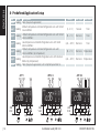
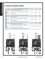
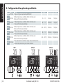
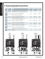
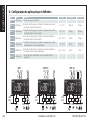
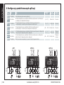
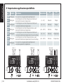
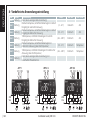
8 - Predefined Application Setup
App Mode Description Temp. Def. type Def. end
App 0 Cooling None (no preset application)
App 1 Cooling
Medium temperature ventilated refrigeration units with timed
natural defrost
(2 – 6 °C) Natural Time
App 2 Cooling
Medium temperature ventilated refrigeration units with timed
electrical defrost
(0 – 4 °C) Electrical Time
App 3 Cooling
Low temperature ventilated refrigeration units with timed
electrical defrost
(-26 – -20 °C) Electrical Time
App 4 Cooling
Medium temperature ventilated refrigeration units with
electrical defrost (by temperature)
(0 – 4 °C) Electrical Temperature
App 5 Cooling
Low temperature ventilated refrigeration units with electrical
defrost (by temperature)
(-26 – -20 °C) Electrical Temperature
App 6 Cooling None (no preset application) with simplified parameter list
SairDI1DI2 SairDI1DI2 SairDI1DI2 S5
APP 1APP 2/3 APP 4/5
DO1
230
V AC
DO3DO4 DO1
230
V AC
DO3DO2DO4 DO1
230
V AC
DO3DO
2D
O4

| 15DKRCE.PI.RL0.H7.ML Installation Guide | ERC 214
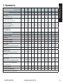
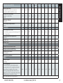
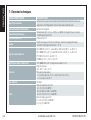
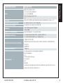
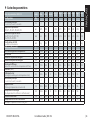
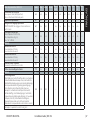
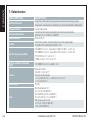
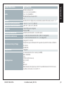
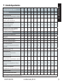
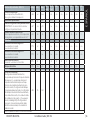
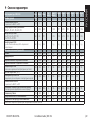
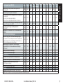
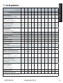
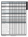
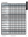
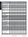
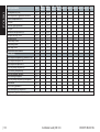
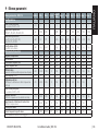
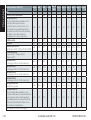
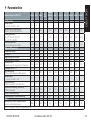
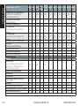
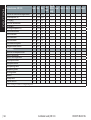
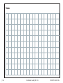
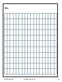
9 - Parameter List
Parameter name - ERC 214 Code Min Max Unit
App. 0
(Def.)
App. 1 App. 2 App. 3 App. 4 App. 5 App. 6
Configuration cFg
Main switch
-1=service, 0=OFF, 1=ON
r12 -1 1 1 1 1 1 1 1 1
Predefined applications
AP0, AP1, AP2, AP3, AP4, AP5, AP6
o61 AP0 AP6 AP0 AP1 AP2 AP3 AP4 AP5 AP6
Sensor type selection
n5=NTC 5 K, n10=NTC 10 K,
Ptc=PTC, Pt1=Pt1000
o06 n5 Pt1 n10 n10 n10 n10 n10 n10 n10
DO4 configuration
Lig=light, ALA=alarm
o36 Lig ALA Lig Lig Lig Lig Lig Lig Lig
Reference/thermostat r--
Temperature setpoint r00 -100.0 200.0 C/F 2.0 4.0 2.0 -24.0 2.0 -24.0 2.0
Differential r01 0.1 20.0 K 2.0 2.0 2.0 2.0 2.0 2.0 2.0
Min set point limitation r02 -100.0 200.0 C/F -35.0 2.0 0.0 -26.0 0.0 -26.0 -35.0
Max set point limitation r03 -100.0 200.0 C/F 50.0 6.0 4.0 -20.0 4.0 -20.0 50.0
Display offset
(correction value in display temperature)
r04 -10.0 10.0 K 0.0 0.0 0.0 0.0 0.0 0.0 0.0
Display Unit (°C/°F) r05 -C -F -C -C -C -C -C -C -C
Calibration of Sair
(offset for air temperature calibration)
r09 -20.0 20.0 K 0.0 0.0 0.0 0.0 0.0 0.0 -
Main switch
-1=service, 0=OFF, 1=ON
r12 -1 1 1 1 1 1 1 1 -
Night set back
(offset temperature during night mode)
r13 -50.0 50.0 K 0.0 0.0 0.0 0.0 0.0 0.0 0.0
Thermostat reference displacement
(offset temperature)
r40 -50.0 50.0 K 0.0 0.0 0.0 0.0 0.0 0.0 -
Pull-down duration r96 0 960 min 0 0 0 0 0 0 -
Pull-down limit temperature r97 -100.0 200.0 C/F 0.0 0.0 0.0 0.0 0.0 0.0 -
Note: hidden parameters are greyed out
ENGLISH

| 16 DKRCE.PI.RL0.H7.MLInstallation Guide | ERC 214
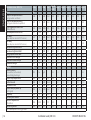
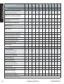
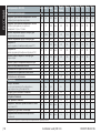
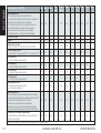
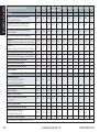
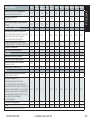
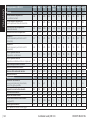
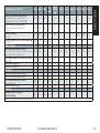
Parameter name - ERC 214 Code Min Max Unit
App. 0
(Def.)
App. 1 App. 2 App. 3 App. 4 App. 5 App. 6
Alarm A--
Delay for temperature alarm
during normal conditions
A03 0 240 min 30 45 30 30 30 30 30
Delay for temperature alarm
during pull-down/start-up/defrost
A12 0 240 min 60 90 60 60 60 60 60
High temperature alarm limit
(Cabinet/Room)
A13 -100.0 200.0 C/F 8.0 10.0 8.0 -15.0 8.0 -15.0 8.0
Low temperature alarm limit A14 -100.0 200.0 C/F -30.0 0.0 -2.0 -30.0 -2.0 -30.0 -30.0
DI1 delay
(time delay for selected DI1 function)
A27 0 240 min 30 30 30 30 30 30 30
DI2 delay
(time delay for selected DI2 function)
A28 0 240 min 30 30 30 30 30 30 30
Condenser high alarm limit A37 0 200 C/F 80 80 80 80 80 80 -
Condenser high block limit A54 0 200 C/F 85 85 85 85 85 85 -
Voltage protection enable A72 no yES no no no no no no no
Minimum cut-in voltage A73 0 270 V 0 0 0 0 0 0 0
Minimum cut-out voltage A74 0 270 V 0 0 0 0 0 0 0
Maximum voltage A75 0 270 V 270 270 270 270 270 270 270
Defrost d--
Defrost method
no=no defrost, nAt=natural,
EL=electrical, gAS=hot gas
d01 no gAS EL nAt EL EL EL EL EL
Defrost stop temperature d02 0.0 50.0 C/F 6.0 - - - 6.0 6.0 6.0
Defrost interval d03 0 240 hours 8 6 8 12 8 12 8
Max defrost time d04 0 480 min 30 45 15 15 30 30 30
Defrost delay at power up
(or DI signal)
d05 0 240.0 min 0 0 0 0 0 0 -
Drip delay d06 0 60 min 0 0 0 0 0 0 5
Fan delay after defrost d07 0 60 min 0 0 0 0 0 0 5
Fan start temperature
after defrost
d08 -50.0 0.0 C/F -5.0 - - - -5.0 -5.0 -
Fan during defrost d09 oFF on on on on on on on on
Note: hidden parameters are greyed out
ENGLISH

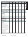
| 17DKRCE.PI.RL0.H7.ML Installation Guide | ERC 214
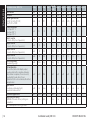
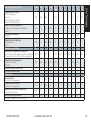
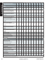
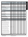
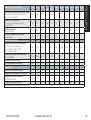
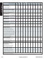
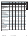
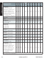
Parameter name - ERC 214 Code Min Max Unit
App. 0
(Def.)
App. 1 App. 2 App. 3 App. 4 App. 5 App. 6
Defrost stop sensor
configuration non=time, Air=Sair (air
temperature), dEF=S5 (defrost sensor)
d10 non dEF non non non non dEF dEF non
Compressor accumulated
runtime to start defrost
0=OFF
d18 0 96 hours 0 0 0 0 0 0 -
Defrost on demand
20.0=OFF
d19 0.0 20.0 K 20.0 - - - 20.0 20.0 -
Defrost delay after pull-down
0=OFF
d30 0 960 min 0 0 0 0 0 0 -
Fan control F--
Fan at compressor cutout
FFc=fan follow compressor, FAo=fan always ON,
FPL= fan pulsating
F01 FFc FPL FAo FAo FAo FAo FAo FAo FAo
Fan stop evaporator temperature
50.0=OFF
F04 -50.0 50.0 C/F 50.0 - - - 50.0 50.0 -
Fan ON cycle F07 0 15 min 2 2 2 2 2 2 2
Fan OFF cycle F08 0 15.0 min 2 2 2 2 2 2 2
Compressor c--
Compressor minimum ON time C01 0 30 min 0 0 0 0 0 0 0
Compressor minimum OFF time C02 0 30 min 2 2 2 2 2 2 2
Compressor OFF delay
at door open
C04 0 15 min 0 0 0 0 0 0 1
Zero crossing selection C70 no yES yES yES yES yES yES yES yES
Others o--
Delay of outputs
at startup
o01 0 600 min 5 5 5 5 5 5 5
DI1 configuration
oFF=not used, Sdc=status display output,
doo=door alarm with resumption, doA=door
alarm without resumption, SCH = main
switch, nig=day/ night mode, rFd=reference
displacement, EAL=external alarm, dEF=defrost,
Pud=pull-down, Sc=condenser sensor
o02 oFF Sc oFF oFF oFF oFF oFF oFF oFF
Note: hidden parameters are greyed out
ENGLISH

| 18 DKRCE.PI.RL0.H7.MLInstallation Guide | ERC 214
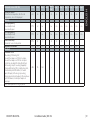
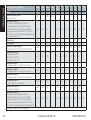
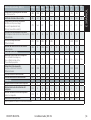
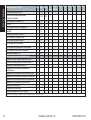
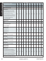
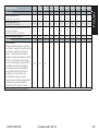
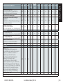
Parameter name - ERC 214 Code Min Max Unit
App. 0
(Def.)
App. 1 App. 2 App. 3 App. 4 App. 5 App. 6
Serial address o03 0 247 0 0 0 0 0 0 -
Password o05 no 999 no no no no no no 0
Sensor type selection
n5=NTC 5 K, n10=NTC 10 K,
Ptc=PTC, Pt1=Pt1000
o06 n5 Pt1 n10 n10 n10 n10 n10 n10 -
Display Resolution
0.1=steps of 0.1 °C
0.5=steps of 0.5 °C,
1.0=steps of 1.0 °C
o15 0.1 1.0 0.1 0.1 0.1 0.1 0.1 0.1 0.1
Relay 1 counter
(1 count=100 cycles of operation)
o23 0 999 0 0 0 0 0 0 -
Relay 2 counter
(1 count=100 cycles of operation)
o24 0 999 0 0 0 0 0 0 -
Relay 3 counter
(1 count=100 cycles of operation)
o25 0 999 0 0 0 0 0 0 -
Relay 4 counter
(1 count=100 cycles of operation)
o26 0 999 0 0 0 0 0 0 -
DO4 configuration
ALA=alarm, Lig=light
o36 ALA Lig Lig Lig Lig Lig Lig Lig -
DI2 configuration
oFF=not used, Sdc=status display output,
doo=door alarm with resumption, doA=door
alarm without resumption, SCH=main switch,
nig=day/night mode, rFd=reference
displacement, EAL=external alarm, dEF=defrost,
Pud=pull-down
o37 oFF Pud oFF oFF oFF oFF oFF oFF oFF
Light Control
on=always on, dAn=day/night,
doo=based on door action
o38 on doo on on on on on on on
Predefined applications o61 AP0 AP6 AP0 AP1 AP2 AP3 AP4 AP5 -
Save settings as factory
WARNING: the earlier factory settings are
overwritten
o67 no yES no no no no no no -
Note: hidden parameters are greyed out
ENGLISH

| 19DKRCE.PI.RL0.H7.ML Installation Guide | ERC 214
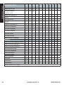
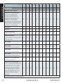
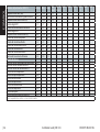
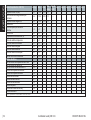
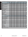
Parameter name - ERC 214 Code Min Max Unit
App. 0
(Def.)
App. 1 App. 2 App. 3 App. 4 App. 5 App. 6
Display at defrost
Air=actual air temperature, FrE=freezed
temperature, -d-="-d-" is displayed
o91 Air -d- -d- -d- -d- -d- -d- -d- -d-
Polarity P--
DI1 input polarity
nc=normally closed,
no=normally open
P73 nc no no no no no no no no
DI2 input polarity
nc=normally closed,
no=normally open
P74 nc no no no no no no no no
Invert alarm relay
0=normal, 1=invert relay action
P75 0 1 0 0 0 0 0 0 -
Keyboard lock enable P76 no yES no no no no no no -
Readouts u--
Controller status
S0=cooling ON/Heating ON,
S2=wait for compressor ON time to elapse,
S3=wait for compressor OFF time to elapse-
restart time, S4=drip OFF delay after defrost,
S10=cooling stop S11=cooling stopped by
thermostat/heating OFF, S14=defrosting state,
S15=fan delay state after defrost, S17=door
open (DI input), S20=emergency cooling,
S25=manual control of outputs, S30=continous
cycle/Pull-down, S32=delay of outputs at
power up
u00 S0 S32 --
Note: hidden parameters are greyed out
ENGLISH

| 20 DKRCE.PI.RL0.H7.MLInstallation Guide | ERC 214
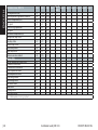
Parameter name - ERC 214 Code Min Max Unit
App. 0
(Def.)
App. 1 App. 2 App. 3 App. 4 App. 5 App. 6
Air temperature (Sair) u01 -100.0 200.0 C/F ---
Read the present regulation reference u02 -100.0 200.0 C/F ---
Defrost temperature (S5) u09 -100.0 200.0 C/F --- - - -
DI1 input u10 oFF on ---
Status of night operation u13 oFF on ---
DI2 input u37 oFF on ---
Condenser temperature (Sc) U09 -100.0 200.0 C/F ---
Compressor relay status u58 oFF on ---
Fan relay status u59 oFF on ---
Defrost relay status u60 oFF on ---
Alarm relay status u62 oFF on ---
Light relay status u63 oFF on ---
Firmware version readout u80 000 999 ---
Alarm status
Sair air temperature sensor error E29
S5 defrost sensor error E27
Sc condenser sensor error E30
High temperature alarm A01
Low temperature alarm A02
High voltage alarm A99
Low voltage alarm AA1
Condenser alarm A61
Door alarm A04
Standby alarm A45
DI external alarm A15
Note: hidden parameters are greyed out
ENGLISH
La pagina si sta caricando...
La pagina si sta caricando...
La pagina si sta caricando...
La pagina si sta caricando...
La pagina si sta caricando...
La pagina si sta caricando...
La pagina si sta caricando...
La pagina si sta caricando...
La pagina si sta caricando...
La pagina si sta caricando...
La pagina si sta caricando...
La pagina si sta caricando...
La pagina si sta caricando...
La pagina si sta caricando...
La pagina si sta caricando...
La pagina si sta caricando...
La pagina si sta caricando...
La pagina si sta caricando...
La pagina si sta caricando...
La pagina si sta caricando...
La pagina si sta caricando...
La pagina si sta caricando...
La pagina si sta caricando...
La pagina si sta caricando...
La pagina si sta caricando...
La pagina si sta caricando...
La pagina si sta caricando...
La pagina si sta caricando...
La pagina si sta caricando...
La pagina si sta caricando...
La pagina si sta caricando...
La pagina si sta caricando...
La pagina si sta caricando...
La pagina si sta caricando...
La pagina si sta caricando...
La pagina si sta caricando...
La pagina si sta caricando...
La pagina si sta caricando...
La pagina si sta caricando...
La pagina si sta caricando...
La pagina si sta caricando...
La pagina si sta caricando...
La pagina si sta caricando...
La pagina si sta caricando...
La pagina si sta caricando...
La pagina si sta caricando...
La pagina si sta caricando...
La pagina si sta caricando...
La pagina si sta caricando...
La pagina si sta caricando...
La pagina si sta caricando...
La pagina si sta caricando...
La pagina si sta caricando...
La pagina si sta caricando...
La pagina si sta caricando...
La pagina si sta caricando...
La pagina si sta caricando...
La pagina si sta caricando...
La pagina si sta caricando...
La pagina si sta caricando...
La pagina si sta caricando...
La pagina si sta caricando...
La pagina si sta caricando...
La pagina si sta caricando...
La pagina si sta caricando...
La pagina si sta caricando...
La pagina si sta caricando...
La pagina si sta caricando...
La pagina si sta caricando...
La pagina si sta caricando...
La pagina si sta caricando...
La pagina si sta caricando...
La pagina si sta caricando...
La pagina si sta caricando...
La pagina si sta caricando...
La pagina si sta caricando...
La pagina si sta caricando...
La pagina si sta caricando...
La pagina si sta caricando...
La pagina si sta caricando...
La pagina si sta caricando...
La pagina si sta caricando...
La pagina si sta caricando...
La pagina si sta caricando...
La pagina si sta caricando...
La pagina si sta caricando...
La pagina si sta caricando...
La pagina si sta caricando...
La pagina si sta caricando...
La pagina si sta caricando...
La pagina si sta caricando...
La pagina si sta caricando...
La pagina si sta caricando...
La pagina si sta caricando...
La pagina si sta caricando...
La pagina si sta caricando...
La pagina si sta caricando...
La pagina si sta caricando...
La pagina si sta caricando...
La pagina si sta caricando...
La pagina si sta caricando...
La pagina si sta caricando...
La pagina si sta caricando...
La pagina si sta caricando...
La pagina si sta caricando...
La pagina si sta caricando...
La pagina si sta caricando...
La pagina si sta caricando...
La pagina si sta caricando...
La pagina si sta caricando...
La pagina si sta caricando...
La pagina si sta caricando...
La pagina si sta caricando...
La pagina si sta caricando...
La pagina si sta caricando...
La pagina si sta caricando...
La pagina si sta caricando...
La pagina si sta caricando...
La pagina si sta caricando...
La pagina si sta caricando...
La pagina si sta caricando...
La pagina si sta caricando...
La pagina si sta caricando...
La pagina si sta caricando...
La pagina si sta caricando...
La pagina si sta caricando...
La pagina si sta caricando...
La pagina si sta caricando...
La pagina si sta caricando...
La pagina si sta caricando...
La pagina si sta caricando...
La pagina si sta caricando...
-
 1
1
-
 2
2
-
 3
3
-
 4
4
-
 5
5
-
 6
6
-
 7
7
-
 8
8
-
 9
9
-
 10
10
-
 11
11
-
 12
12
-
 13
13
-
 14
14
-
 15
15
-
 16
16
-
 17
17
-
 18
18
-
 19
19
-
 20
20
-
 21
21
-
 22
22
-
 23
23
-
 24
24
-
 25
25
-
 26
26
-
 27
27
-
 28
28
-
 29
29
-
 30
30
-
 31
31
-
 32
32
-
 33
33
-
 34
34
-
 35
35
-
 36
36
-
 37
37
-
 38
38
-
 39
39
-
 40
40
-
 41
41
-
 42
42
-
 43
43
-
 44
44
-
 45
45
-
 46
46
-
 47
47
-
 48
48
-
 49
49
-
 50
50
-
 51
51
-
 52
52
-
 53
53
-
 54
54
-
 55
55
-
 56
56
-
 57
57
-
 58
58
-
 59
59
-
 60
60
-
 61
61
-
 62
62
-
 63
63
-
 64
64
-
 65
65
-
 66
66
-
 67
67
-
 68
68
-
 69
69
-
 70
70
-
 71
71
-
 72
72
-
 73
73
-
 74
74
-
 75
75
-
 76
76
-
 77
77
-
 78
78
-
 79
79
-
 80
80
-
 81
81
-
 82
82
-
 83
83
-
 84
84
-
 85
85
-
 86
86
-
 87
87
-
 88
88
-
 89
89
-
 90
90
-
 91
91
-
 92
92
-
 93
93
-
 94
94
-
 95
95
-
 96
96
-
 97
97
-
 98
98
-
 99
99
-
 100
100
-
 101
101
-
 102
102
-
 103
103
-
 104
104
-
 105
105
-
 106
106
-
 107
107
-
 108
108
-
 109
109
-
 110
110
-
 111
111
-
 112
112
-
 113
113
-
 114
114
-
 115
115
-
 116
116
-
 117
117
-
 118
118
-
 119
119
-
 120
120
-
 121
121
-
 122
122
-
 123
123
-
 124
124
-
 125
125
-
 126
126
-
 127
127
-
 128
128
-
 129
129
-
 130
130
-
 131
131
-
 132
132
-
 133
133
-
 134
134
-
 135
135
-
 136
136
-
 137
137
-
 138
138
-
 139
139
-
 140
140
-
 141
141
-
 142
142
-
 143
143
-
 144
144
-
 145
145
-
 146
146
-
 147
147
-
 148
148
-
 149
149
-
 150
150
-
 151
151
-
 152
152


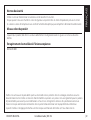
Danfoss 080G3296 Guida d'installazione
- Tipo
- Guida d'installazione
in altre lingue
- português: Danfoss 080G3296 Guia de instalação
Documenti correlati
-
Danfoss ERC 214 Digital controller for refrigeration and defrost, 4 relay Guida d'installazione
-
-
-
Danfoss 080G3293 Guida d'installazione
-
-
-
-
-
-
Altri documenti
-
Carel PJ easy XL Manuale utente
-
JUNG TVA110WW Istruzioni per l'uso
-
Mi Mi Headphones Comfort Manuale utente
-
Pego ECP 200 Base 2 Quick Manual
-
Carel ir33+ Guida Rapida
-
Ascon tecnologic D8 Manuale utente
-
GGM Gastro BRF207D#2#SG12 Manuale del proprietario
-
RKC INSTRUMENT COM-ME-3 Manuale utente
-
-