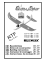
MULTIPLEX EasyStar 13200 Building Instructions
- Categoria
- Giocattoli
- Tipo
- Building Instructions
Questo manuale è adatto anche per

1
F
GB
D
E
I
RTF-Modell 40 MHz # 1 3200
RTF-Modell 41 MHz # 1 3201
RTF-Modell 35 MHz # 1 3202
RTF-Modell 72 MHz # 1 3203
RTF
R
eady
T
o
F
ly!
Bauanleitung 04 - 11
Notice de construction 12 - 19
Building instructions 20 - 27
Instruzioni di montaggio 28 - 35
Instrucciones de montaje 36 - 43

3
D
F
GB
I
E
Sicherheitshinweise
-
Prüfen Sie vor jedem Start den festen Sitz des Motors und der Luftschrauben - insbesondere nach dem Transport, härteren
Landungen sowie Abstürzen. Prüfen Sie ebenfalls vor jedem Start den festen Sitz und die richtige Position der Tragflächen auf dem
Rumpf.
- Akku erst einstecken, wenn Ihr Sender eingeschaltet ist und Sie sicher sind, daß das Bedienelement für die Motorsteuerung auf
"AUS" steht.
- Im startbereiten Zustand nicht in den Bereich der Luftschraube greifen.
Vorsicht in der Luftschraubendrehebene - auch Zuschauer zur Seite bitten!
- Zwischen den Flügen die Motortemperatur durch vorsichtige Fingerprobe prüfen und
vor einem Neustart den Motor ausreichend abkühlen lassen. Die Temperatur ist richtig, wenn Sie den Motor problemlos berühren
können. Insbesondere bei hohen Außentemperaturen kann dieses bis zu 15 Minuten dauern.
- Denken Sie immer daran: Niemals auf Personen und Tiere zufliegen.
Conseils de sécurité
-
Avant chaque décollage, vérifiez la fixation du moteur et de l'hélice, notamment après le transport, après les atterrissages violents
et après un “Crash”. Vérifiez également, avant chaque décollage la fixation ainsi que le positionnement de l’aile par rapport au
fuselage.
- Ne branchez l’accu de propulsion que si vous êtes sûr que votre émetteur est allumé et que l’élément de commande moteur est en
position “ARRET”.
- Ne mettez pas vos doigts dans l’hélice! Attention à la mise en marche, demandez également aux spectateurs de reculer.
- Entre deux vols, vérifiez en posant un doigt dessus, la température du moteur, laissezle refroidir suffisamment avant le prochain
décollage. La température est correcte si vous pouvez maintenir votre doigt ou votre main sur le moteur. Le temps de refroidissement
peut varier jusqu’à 15 minutes s’il fait particulièrement chaud.
- Pensez-y toujours: ne volez jamais vers ou au-dessus des personnes ou des animaux.
Safety notes
-
Before every flight check that the motor and propeller are in place and secure - especially after transporting the model, and after
hard landings and crashes. Check also that the wing is correctly located and firmly secured on the fuselage before each flight.
- Don’t plug in the battery until you have switched on the transmitter, and you are sure that the motor control on the transmitter is set
to “OFF”.
- When the model is switched on, ready to fly, take care not to touch the propeller. Keep well clear of the propeller disc too, and ask
spectators to stay back.
- Allow the motor to cool down after each flight. You can check this by carefully touching the motor case with your finger. The
temperature is correct when you can hold your finger on the case without any problem. On hot days this may take up to 15 minutes.
- Please keep in mind at all times: don’t fly towards people or animals.
Note di sicurezza
-
Prima di ogni decollo controllare che il motore e la eliche siano fissati stabilmente - specialmente dopo il trasporto, atterraggi duri
e se il modello è precipitato. Controllare prima del decollo anche il fissaggio e la posizione corretta delle ali sulla fusoliera.
- Collegare la batteria solo quando la radio è inserita ed il comando del motore è sicuramente in posizione ”SPENTO”.
- Prima del decollo non avvicinarsi al campo di rotazione della eliche. Attenzione alla eliche in movimento - pregare che eventuali
spettatori si portino alla dovuta distanza di sicurezza!
- Tra un volo e l’altro controllare cautamente con le dita la temperatura del motore e farli raffreddare sufficientemente prima di ogni
nuovo decollo. La temperatura è giusta se si possono toccare senza problemi. Specialmente con una temperatura esterna alta
questo può durare fino a 15 minuti.
- Fare attenzione: Non volare mai nella direzione di persone ed animali.
Advertencias de seguridad
-
Compruebe antes de cada despegue que el motor y la hélice estén fuertemente sujetados, sobretodo después de haberlo transportado,
de aterrizajes más fuertes así como después de una caída. Compruebe igualmente antes de cada despegue que las alas estén bien
sujetas y bien colocadas en el fuselaje.
- Conectar la batería, cuando la emisora esté encendida y Usted esté seguro que el elemento de mando para el motor esté en ”OFF”.
- No meter la mano en la zona inmediata a la hélice cuando el avión esté a punto de despegar. ¡Cuidado con la zona de la hélice!
¡Pedir a los espectadores que se aparten!
- Entre los vuelos hay que comprobar cuidadosamente la temperatura del motor con el dedo y dejar que el motor se enfríe antes de
volver a despegar. La temperatura es correcta, si puede tocar el motor sin problemas. Sobretodo en el caso de temperaturas del
ambiente muy altas, esto puede tardar unos 15 minutos.
- Recuerde: No volar nunca hacía personas o animales.

20
GB
1. Examine your kit carefully!
MULTIPLEX model kits are subject to constant quality checks throughout the production process, and we sincerely
hope that you are (very) happy with the contents of your kit. However, we would ask you to check all the parts
before you start construction, as we cannot exchange components which you have already worked on. If you
find any part is not acceptable for any reason, we will readily correct or exchange it. Just send the component to
our Model Department. Please be sure to include a brief description of the fault.
We are constantly working on improving our models, and for this reason we must reserve the right to change the
kit contents in terms of shape or dimensions of parts, technology, materials and fittings, without prior notification.
Please understand that we cannot entertain claims against us if the kit contents do not agree in every respect with
the instructions and the illustrations.
Caution!
Radio-controlled models, and especially model aircraft, are by no means playthings. Building and operating
them safely requires a certain level of technical competence and manual skill, together with discipline and
a responsible attitude at the flying field. Errors and carelessness in building and flying the model can
result in serious personal injury and damage to property. Since we, as manufacturers, have no control
over the construction, maintenance and operation of our products, we are obliged to take this opportunity
to point out these hazards and to emphasise your personal responsibility.
Additional items required: 8 AA-size dry or rechargeable cells for the transmitter power supply
Second flight pack for even more fun:
MULTIPLEX NiCd flight pack 6 / 500 mAh Order No. 15 5545
Tools:
Allen key, 1.5 mm A/F, included in accessory pack.
Specification:
Wingspan 1370 mm
Overall length 917 mm
Fuselage length 870 mm
All-up weight 400 motor / 6 x AA cells approx. 680 g
Wing area approx. 24 dm²
Wing loading approx. 28 g/ dm²
RC functions Aileron, elevator and motor
Important note - repairs:
This model is not made of styrofoam™, and it is not possible to glue the material using white glue or
epoxy. Please be sure to use cyano-acrylate glue exclusively, preferably in conjunction with cyano activator
(kicker). We recommend medium-viscosity cyano. This is the procedure: spray cyano activator on one
face of the Elapor®; allow it to air-dry, then apply cyano adhesive to the other face. Join the parts,
immediately position them accurately, and wait a few seconds for the glue to cure.
Please take care when handling cyano-acrylate adhesives. These materials harden in seconds, so don’t
get them on your fingers or other parts of the body. We strongly recommend the use of goggles to protect
your eyes. Keep the adhesive out of the reach of children.
1. Before final assembly
Check the contents of your kit.
You will find the parts list helpful here.
2. Final assembly
The tailplane and fin are attached to the fuselage using the double-sided tape provided. However, you must first
run the wire pushrods through the pushrod connectors fitted to the rudder and elevator horns. Peel the backing
paper from the tape and place the tailplane on the model, taking care to position it at right-angles to the fuselage.
Don’t press the parts together firmly initially. Check alignment carefully, then press down firmly. Repeat the procedure
with the fin.
# 1 3200 to 1 3203

21
3. Adjusting the servo linkages
Set the servos and the control surfaces to “neutral”
(centre), then tighten the screws in the pushrod
connectors to secure the wire pushrods.
4. Checking the installation
All components should be installed in the stated
positions and secured using Velcro (hook-and-loop)
tape:
The flight pack should be fitted in the extreme nose,
with the receiver behind it. Even at this early stage it is
a good to check the Centre of Gravity as stated in Point
6. Apply the Velcro tape (“loop” side) to the inside of the
fuselage floor at the flight pack and receiver positions.
If the Velcro tape does not seem to stick strongly enough,
apply a little cyano to the joints.
The final position of the flight pack cannot be determined
until the model is complete and you are able to set the
final CG position. Ensure that the Velcro tape for the
battery is securely fixed to the model.
Check that the battery is held in place firmly before
each flight.
Temporarily connect the receiving system as described
in the instructions supplied with the RC system.
Don’t connect the flight battery to the speed
controller until you have switched on the transmitter
and checked that the motor control (throttle) is at
the “OFF” position.
The model is supplied as standard with a BEC speed
controller, i.e. it draws current for the receiving system
from the flight pack itself. This means that a separate
receiver battery is not required.
Hold the model securely and switch the motor on briefly,
so that you can check the direction of rotation of the
propeller. Before you do this remove any loose,
lightweight objects from the area behind the model
before the propeller does it for you.
Caution: even small motors and propellers are
capable of inflicting injury.
5. Gilding the lily - applying the decals
The kit is supplied with a multi-colour decal sheet. Cut
out the individual name placards and emblems and apply
them to the model in the position shown in the kit box
illustration, or in an arrangement which you find
pleasing. The cabin can be coloured using a black wa-
terproof felt-tip pen, continuing the colour down to the
edge.
6. Balancing
The EasyStar, like any other aircraft, must be balanced
at a particular point in order to achieve stable flying
characteristics. Assemble your model ready to fly, and
install the flight battery.
The Centre of Gravity (CG) should be about 5 mm
from the rear edge of the spar cover. Mark this point.
This setting corresponds to about 78 mm from the
root leading edge, measured on both sides of the
fuselage.
Support the model at this point on two fingertips and it
should balance level. If not, you can move the flight
battery forward or aft to correct the balance point. Once
the correct position is found, mark the position of the
battery inside the model to ensure that the pack is always
replaced in the same position.
7. Preparing for the first flight
For the first flight wait for a day with as little breeze as
possible. The early evening is often a good time.
Be sure to carry out a range check before the first
flight.
Just before the flight, charge up the transmitter battery
and the flight pack using the recommended procedures.
Ensure that “your” channel is not already in use before
you switch on the transmitter.
Ask your assistant to walk away from the model, holding
the transmitter. The aerial should be fitted but completely
collapsed.
Your assistant should operate one of the functions
constantly while you watch the servos. The non-
controlled servo should stay motionless up to a range
of about 60 m, and the controlled one should follow the
stick movements smoothly and without any delay. Please
note that this check can only give reliable results if the
radio band is clear of interference, and if no other radio
control transmitters are in use - even on different
channels. If the range check is successful, repeat it with
the motor running. There should be only a very slight
reduction in effective radio range with the motor turning.
If you are not sure about anything, please don’t risk a
flight. Send the whole system (including battery, switch
harness and servos) to the service department of your
RC system manufacturer and ask them to check it.
The first flight ...
Don’t try unpowered test-glides with this model!
The EasyStar is designed for hand-launching, and
should always be launched exactly into any wind.
5mm
78mm

22
Quick Charger CG-72
1. Connect the Charger to 12V source battery (automobile is recommended).
2. Connect Nicad battery pack to charger.
3. Set the charger timer at 30 min. (600 mA battery)
4. Green light (LED) will be lit while it is being charged.
5. LED will go out when it is fully charged.
Battery Care Tips
- Do not have the motor of your car running when you are charging the Nicad Battery. This may cause overcharging
of your battery (Note: 600mA Nicad battery pack should not be charged over 30 minutes).
- Heat is the number one cause of battery failure.
- The motor battery should never become so hot during the charge process that you are unable to handle it.
- The motor battery will become warm during the flight; wait until the battery is cool to the touch before re-charging
it.
- Discharge remaining power in Nicad battery by operating propeller after landing.
- The Nicad battery can go bad over prolonged usage; replace it if the flying time gets considerably shorter over
time.
- Never charge the battery while battery is installed in the plane.
If you are a beginner to model flying we strongly
recommend that you ask an experienced model pilot
to help you for the first few flights.
Allow the model to climb to a safe height, then adjust
the trim sliders on the transmitter until it flies in a perfectly
straight line “hands off”.
While the model is still at a safe altitude, switch off the
motor and try out the controls on the glide. Carry out a
“dry run” landing approach at a safe height so that you
are prepared for the real landing when the battery runs
flat.
Don’t try any tight turns at first, and especially not on
the landing approach at low altitude. It is always better
to land safely at some distance from you, than to force
the model back to your feet and risk a heavy landing.
8. Safety
Safety is the First Commandment when flying any model
aircraft. Third party insurance should be considered a
basic essential. If you join a model club suitable cover
will usually be available through the organisation. It is
your personal responsibility to ensure that your
insurance is adequate (i.e. that its cover includes
powered model aircraft).
Make it your job to keep your models and your radio
control system in perfect order at all times. Check the
correct charging procedure for the NC batteries you are
using. Make use of all sensible safety systems and
precautions which are advised for your system. An
excellent source of practical accessories is the MULTI-
PLEX main catalogue, as our products are designed
and manufactured exclusively by practising modellers
for other practising modellers.
Always fly with a responsible attitude. You may think
that flying low over other people’s heads is proof of your
piloting skill; others know better. The real expert does
not need to prove himself in such childish ways. Let
other pilots know that this is what you think too. Always
fly in such a way that you do not endanger yourself or
others. Bear in mind that even the best RC system in
the world is subject to outside interference. No matter
how many years of accident-free flying you have under
your belt, you have no idea what will happen in the next
minute.
We - the MULTIPLEX team - hope you have many hours
of pleasure building and flying your new model.
MULTIPLEX Modellsport GmbH & Co. KG
Product development and maintenance
Klaus Michler
Parts list for the EasyStar RTF model # 1 3200 to # 1 3203
Part No. Description
No. off
1 1 Building instructions
2 1 Decal set
3 1 Fuselage with factory-fitted power system, receiver, 2 servos,
speed controller and canopy; 6/600 mAh flight battery
4 1 Wing set; factory-fitted spar holder
5 1 Tailplane and elevator; factory-fitted horn
6 1 Fin and rudder; factory-fitted horn
7 1 Wing joiner tube
8 1 Transmitter
9 1 Battery charger
10 1 Allen key, 1.5 mm A/F
GB

23
Fuselage
Canopy
L.H. wing
panel
Rudder
Elevator
Fin
Tailplane
Motor pod
R.H. wing
panel
Longitudinal axis
vertical axis
lateral axis
GB
Basic information relating to model aircraft
Any aircraft, whether full-size or model, can be controlled around the three primary axes: vertical (yaw), lateral (pitch) and
longitudinal (roll).
When you operate the elevator, the model’s attitude alters around the lateral axis. If you apply a rudder command, the model
swings around the vertical axis. If you move the aileron stick, the model rolls around its longitudinal axis. As our EasyStar has
considerable wing dihedral, ailerons are not required for roll control. In this case the rudder is used both to turn the model
around the vertical axis, and also to roll it (longitudinal axis). External influences such as air turbulence may cause the model
to deviate from its intended flight path, and when this happens the pilot must control the model in such a way that it returns to
the required direction. The basic method of controlling the model’s height (altitude) is to vary motor speed (motor and propeller).
The rotational speed of the motor is usually altered by means of a speed controller. Applying up-elevator also causes the model
to gain height, but at the same time it loses speed, and this can only be continued until the model reaches its minimum
airspeed and stalls. The maximum climb angle varies according to the power available from the motor.
Wing section
The wing features a cambered airfoil section over which the
air flows when the model is flying. In a given period of time
the air flowing over the top surface of the wing has to cover a
greater distance than the air flowing under it. This causes a
reduction in pressure on the top surface, which in turn creates
a lifting force which keeps the aircraft in the air. Fig. A
Centre of Gravity (CG)
To achieve stable flying characteristics your model aircraft must
balance at a particular point, just like any other aircraft. It is
absolutely essential to check and set the correct CG position
before flying the model for the first time.
The CG position is stated as a distance which is measured
aft from the wing root leading edge, i.e. close to the fuselage.
Support the model at this point on two fingertips (or - better -
use the MPX CG gauge, # 69 3054); the model should now
hang level. Fig. B
If the model does not balance level, the installed components
(e.g. flight battery) can be re-positioned inside the fuselage. If
this is still not sufficient, attach the appropriate quantity of
trim ballast (lead or plasticene) to the fuselage nose or tail
and secure it carefully. If the model is tail-heavy, fix the ballast
at the fuselage nose; if the model is tail-heavy, attach the
ballast at the tail end of the fuselage.
The longitudinal dihedral is the difference in degrees between
the angle of incidence of the wing and of the tail. Provided
that you work carefully and attach the wing and tailplane to
the fuselage without gaps, the longitudinal dihedral will be
correct automatically.
If you are sure that both these settings (CG and longitudinal
dihedral) are correct, you can be confident that there will be
no major problems when you test-fly the model. Fig. C
Control surfaces, control surface travels
The model will only fly safely, reliably and accurately if the
control surfaces move freely and smoothly, follow the stick
movements in the correct “sense”, and move to the stated
maximum travels. The travels stated in these instructions have
been established during the test-flying programme, and we
strongly recommend that you keep to them initially. You can
always adjust them to meet your personal preferences later
on.
Transmitter controls
The transmitter features two main sticks which the pilot moves
to control the servos in the model, which in turn operate the
control surfaces.
The functions are assigned according to Mode A, although
other stick modes are possible.
The transmitter controls the control surfaces as follows:
Rudder (left / right) Fig. D
Elevator (up / down) Fig. E
Throttle (motor off / on) Fig. F
Unlike the other controls, the throttle stick must not return to
the neutral position automatically. Instead it features a ratchet
so that it stays wherever you put it. Please read the instructions
supplied with your radio control system for the method of
setting up and adjusting the transmitter and receiving system.

24
Speed Controller MULTIcont X-08 # 7 2270
These operating instructions are an integral part of the product,
and contain important information and safety notes. They should
therefore be kept accessible at all times, and must be passed on
to the new owner if you ever dispose of the product.
1. Specification
MULTIcont X-08 # 7 2270
Cell count battery voltage 5-10 / ~4,7 – 15 V
Continuous current (with good cooling) 8 A (max. 11A)
Pulse frequency ~ 6 kHz
Receiver power supply (BEC):
BEC voltage 5 V
BEC current max. 1 A
Dissipated power of BEC regulator max. 11 W
( with 8 cells max 5 W)
Dimensions (w/o wires) 10x21x6 mm
Weight without / with wires 2/17 g
2. Safety Notes
• Read the instructions before using the unit
• Avoid heat build-up: Do not restrict air circulation
• Do not connect the flight battery with reversed polarity:
Connecting a battery incorrectly immediately wrecks the
controller.
For this reason: • red wire to POSITIVE (+) terminal,
• black wire to NEGATIVE (-) terminal
We recommend to use the green MPX-plugs # 85213/85214 for
ESC/Battery and Motor/ESC as long as the motor is not soldered to
the motor directly.
• When soldering or otherwise working on the motor or
controller:
Always disconnect the battery first (short-circuit / injury
hazard)
• Please note when running or test-running the power system:
Do not run the motor holding it in your hand; secure the model well.
Check that there is space all round for the propeller to rotate. Remove
any objects (clothing, small items, paper, etc.) from the vicinity of
the propeller which could be sucked into it or blown away by it. Never
stand in front of, or in line with the rotational plane of the propeller
(injury hazard).
3. Special Characteristics
• BEC with low-voltage cut-off (recommended up to max.8 cells)
with automatic cell count detection
• Power-on guard: the controller stays in the disarmed state when
you connect the flight battery. The motor cannot be switched on until
you first move the throttle stick briefly to the idle position.
• Overload-/overheat-protection: When the temperature rises, the
voltage rises also. When the voltage is to high, the controller will
switch off the motor and the LED will flash. To activate the motor
again, the battery must be disconnected from the controller and
connected again.
• Over-Cell-protection – The controller will switch off at 16V
4. Mounting the controller on the motor
Note: in most cases soldering is required to install the controller.
Soldering calls for a certain amount of care, as the correct operation
and reliability of the power system are dependent upon these joints.
• Use only cored solder designed for electronic soldering
• Do not use an acid-based soldering flux
• Parts to be soldered must be heated to the correct temperature,
but must not be overheated
• If you have not soldered before, ask an experienced modeller
for help.
1. Motor suppression: if the motor you wish to use is not
suppressed as standard, we strongly recommend the use of the
suppressor set # 8 5020, to avoid potential problems with
interference to the receiving system.
2. Solder the motor leads attached to the controller to the
motor Solder the motor power leads these wires to the drive
motor terminals as follows:
Generally with direct-drive motors: yellow
Æ “+” ; blue Æ “-“
3. Check the direction of motor rotation
If the direction of rotation is not correct (e.g. when using a geared
motor), correct this by swapping over the leads at the motor
terminals (re-solder the joints).
5. Using the power system for the first time
1. Connect the receiver lead on the controller (REC) to the receiver.
With MPX RC-systems: channel 4 = throttle/motor
2. If you own a programmable transmitter:
set servo travel for throttle / motor to 100% on both sides.
3. Move the throttle stick (
and the associated trim slider) fully to the
desired idle /motor STOP position.
4. Switch on the transmitter
5. Connect the flight battery to the speed controller
Caution: reverse polarity will wreck the controller instantly!
If the LED flashs, the controller is in power-on guard mode.
Æ Disconnect the flight battery from the controller, reverse the throttle
channel at the transmitter (servo reverse) and connect the flight battery
again
Æ Ready.
Important:
• Always switch transmitter ON first, then connect the flight
battery. If you now see the LED flashing, the controller is in
power-on guard mode.
Æ Move the throttle stick to idle Æ the
controller is ready for use!
• First disconnect the flight battery from the controller, then
switch the transmitter OFF.
6. BEC =
Battery Eliminating Circuit
BEC means: receiver and servos draw current from the flight battery.
Do not use a separate receiver battery.
Note: please remember that the BEC system of the MULTIcont X-08
can only supply its maximum 1 A current briefly. In practice this means:
With 7 cells Connect not more than 3, with 8 cells not more than 2
servos to the receiver! Don’t use BEC with more than 8 cells!
Servo current drain varies according to the power class of the servos,
the frequency of control commands, and the freedom of movement of
the control surface linkages (!). If you cannot measure the BEC current:
Carry out a check “on the ground” by operating the servos constantly
until the low-voltage cut-off is triggered (= flat flight battery). At this point
the speed controller should be no more than warm to the touch, and the
servos should operate correctly during the entire period.
If your model is fitted with more servos than the controller can cope
with, the BEC power supply must be disabled and a separate receiver
battery used. This is done by locating the red (+) wire in the receiver
lead attached to the controller, and cutting it through.
7. Low battery cut-off
The low battery cut-off of the MULTIcont X-08 is designed to switch off
the motor when the flight battery is almost discharged. This ensures
that there is still sufficient energy in the pack to power the BEC system
for a safe landing. When the battery is nearly flat, you will also notice
the motor’s power output (propeller speed) declining rapidly. This is the
time to start preparing for the landing approach.
When voltage less 4.7 V is reached than the controller switches off the
motor. The power system can be switched on again for a brief period if
required by moving the throttle stick momentarily to the idle / motor
STOP position.
GB

25
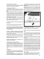
III. System-Layout
aerial
handle
motor
channel 3
display
rudder stick
channel 1
rudder trim
setting
On / Off
switch
crystal
elevator-stick
elevator trim
setting
Mixer
on / off
Charging jack
Servo-Reverse
rudder
Servo-Reverse
elevator
RANGER III
GB
III. System-Layout
I. Introduction
II. Features and Specifications
III. System Layout
IV. Setting and Operation
1. Transmitter
a. Loading Batteries
b. Reading the LED Battery Indicators
c. Recharging Nicad Batteries
d. Changing Crystals
2. Installation of Receiver and Servos
3. Transmitter, Receiver and Servo Settings
a. Checking Operation of the Servo
b. Elevator and Rudder Servo Trim Settings
- Trim Setting before Flight
- Trim Setting during Flight
c. Adjustable Traveling Volume
I. Introduction
The Ranger 3 FM Sky radio is part of the EasyStar RTF-
Set. The Ranger 3 FM Sky will prepare you to use radio
with more advanced features as your skill level and
desire for greater challenges evolve.
Please read the following instruction carefully before
you
start using the radio.
II. Features and Specifications
A Transmitter
- 3 Channel FM proportional radio control system
- 3 LED battery status indicators
- Charging jack for 3rd party Nicad battery
- Servo reversing for channel 1 and 2
- Current drain: 180mA
- V-tail or Elevon mixing function
- Proportional 3rd channel slide switch
- ATV for channel 1 and 2
B Receiver
- Narrow Band 4 channel FM receiver
- changeable crystals
C Servo
- 2 lightweight Tiny-S-Servos
D Speed-controller
- small, lightweight ESC MULTIcont X-08
touch your dreams

26
receiver
Servo channel 2 - elevator
channel 3 motor
X-08
accu 6/600 AA
Servo channel 1 - rudder
1. Transmitter
a. Loading Batteries
You may use either Alkaline "AA" size batteries or 3rd
party Nicad batteries.
· Push the bottom battery cover in the direction of the
arrow then lift up the cover
· Load 8 AA batteries (Be sure the polarity is correct)
· Reinstall battery case with installed AA batteries.
· Nicad should be charged before use
c. Recharging Nicad Batteries
The Ranger 3 FM Sky is equipped with an external
charging jack so there is no need to remove the Nicad
batteries from the transmitter. The Hitec CG-22A is made
to charge these type of batteries overnight or for
approximately 12 - 15 hours. Please refer to the following
diagram; check to see that the charge lights are lit after
the connection is complete. It is advisable to cycle your
Nicad batteries at least once every 5 or 6 charges. This
can be done by simply turning your transmitter on with
the antenna connected and extended to let it run
completely dead.(Warning!!! Always extend your
antenna as not to overload the circuitry when radio is
on.), then follow the charging method and repeat this 3
times, this will remove the memory that the battery has
stored up if you just simply charge a half dead pack.
d. Changing Crystals
Changing crystal to avoid conflicts with other aircraft is
possible where permitted. (You must check your local
rules before doing so. If you are allowed to change
crystals, both the transmitter and receiver crystals must
be changed together. You must change within the same
band. Use only Hitec crystals when changing
frequencies.
2. Installation of Receiver and Servos
After connecting the receiver and servos as below illustration, turn on the power
to the transmitter first then turn the receiver on. (Always turn the transmitter ON
first and OFF last.) This will prevent the receiver from picking up stray signals
and going out of control. Now move the controls lo see if the servos are moving
properly. lf not, check your wiring or crystals if the servos do not move at all.
b. Reading the LED Battery Indicators
With new alkaline or freshly charged Nicad, the Green light should be lit. With use, the Green light
will turn to Amber. If the Red begins to flash, operation should be stopped and the batteries should
be recharged or replaced immediately.

27
Transmitter, Receiver and Servo Settings
Now we come to the critical part as proper installation of these components are essential.
a. Checking Operation of the Servo
After installation of the servo and receiver into your model is complete, turn the power "ON" the transmitter (fully
extend the antenna) now turn on the receiver.
Check to see if all servos are working properly. If not, check the connections and/or make sure the main battery
pack is charged.
Check to see that the servos are moving in the correct direction. If not, change the servo direction with the
reversing switches located on the bottom of the radio. The 3rd channel of the Ranger 3 FM Sky is not reversible.
If everything checks out then turn the receiver "OFF" first, then the transmitter.
The Ranger 3 FM Sky offers an internal electronic mix for channels 1 and 2 to deliver an Elevon or V-tail mix for
those aircraft requiring those specific functions. (Not used in your EasyStar)
Always remembers to never have the receiver "ON" without the transmitter being "0N".
This means when turning your model "ON" always turn the transmitter "ON" first and "OFF" last.
(Note: Please makes sure to fold the transmitter antenna after use so as not to get damaged or poke someone in
the eyes.)
Warning!!! : Do not shorten the length of the receiver antenna by cutting off any excess wire.
This will severely affect the operating range and could result in injury to yourself and others.
b. Elevator and Aileron Servo Trim Settings
- Trim Setting before Flight
The servo trim enables minor adjustment of the servo neutral position so that the plane will fly straight when the
stick is in the center position. Before adjusting the servo trim, please make sure that when both the stick and the
servo trim is in it's center position (1) the servo arm is perpendicular to the push rods, and (2) the elevator and
aileron of the plane is flush with the tail wing.
- Trim Setting during Flight
You may perform some minor trim adjustment during flight if the plane nose up or down (Elevator Trim) or sideways
(Aileron Trim) when the stick is in the center position.However please keep in mind that trim adjustment is only for
minor adjustment and major adjustment should still be done through push rod (linkage) adjustment at the model.
(Note: There is no trim adjustment on the 3rd channel of the Ranger 3 FM Sky)
c. Adjustable Traveling Volume
You may use this volume to adjust servo traveling according to the characteristics of your model. The servo travel
can be adjusted from 50% to 100% of the total travel range by turning each ATV knob on the transmitter. Turning
clockwise will increase servo travel and counter clockwise will decrease servo travel.
-
 1
1
-
 2
2
-
 3
3
-
 4
4
-
 5
5
-
 6
6
-
 7
7
-
 8
8
-
 9
9
-
 10
10


MULTIPLEX EasyStar 13200 Building Instructions
- Categoria
- Giocattoli
- Tipo
- Building Instructions
- Questo manuale è adatto anche per
in altre lingue
- English: MULTIPLEX EasyStar 13200
Documenti correlati
-
HiTEC MiniMag RR Manuale del proprietario
-
MULTIPLEX D-KMPX Manuale utente
-
-
-
-
-
-