INTEK HX-174S Manuale del proprietario
- Categoria
- Radio a due vie
- Tipo
- Manuale del proprietario
Questo manuale è adatto anche per

INSTRUCTION MANUAL
MANUALE DI ISTRUZIONI
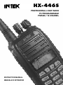
PROFESSIONAL 2-WAY RADIO
PC PROGRAMMABLE
PMR446 / 16 CHANNEL
HX-446S

Declaration of Conformity
With the present declaration, we certify that the following products :
INTEK HX-446S
comply with all the technical regulations applicable to the above mentioned products
in accordance with the EC Directives 2006/95/EC, 2004/108/EC, 99/5/EC.
Type of product : PMR 446 UHF Transceiver
Details of applied standards : EN 300 296-2, EN 301 489-1/-5,
EN 60065
Manufacturer : INTEK S.R.L.
16, Via G. Marconi
20090 Segrate, Italy
Tel. +3902 2695 0451 / Fax. +3902 2695 2185
E-mail : [email protected]
Contact Reference : Armando Zanni
Tel. +3902 2695 0451 / Fax. +3902 2695 2185
E-mail : [email protected]
Segrate, 15/10/2008 dr. Vittorio Zanetti
(General Manager)
DECLARATION OF CONFORMITY
EC Certificate of Conformity
(to EC Directive 2006/95, 2004/108, 99/5)
NOTICE !
It is recommended to carefully read this owner’s manual before using the product. This will also help the user to
prevent using the radio in violation of the regulations valid in the country where the product is used, as well as to
avoid any possible interferences with other services.
RoHS
2002/95/EC

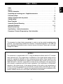
Index . . . . . . . . . . . . . . . . . . . . . . . . . . . . . . . . . . . . . . . . . . . . . . . . . . . . . . . . . . . . . . . . . . . 1
Notice . . . . . . . . . . . . . . . . . . . . . . . . . . . . . . . . . . . . . . . . . . . . . . . . . . . . . . . . . . . . . . . . . . . 1
General information . . . . . . . . . . . . . . . . . . . . . . . . . . . . . . . . . . . . . . . . . . . . . . . . . . . . . . . 2
Unpacking and checking parts - Supplied accessories . . . . . . . . . . . . . . . . . . . . . . . . . . 3
Preliminary Steps . . . . . . . . . . . . . . . . . . . . . . . . . . . . . . . . . . . . . . . . . . . . . . . . . . . . . . . 4-6
Getting acquainted with the product . . . . . . . . . . . . . . . . . . . . . . . . . . . . . . . . . . . . . . . . 7-9
Getting started . . . . . . . . . . . . . . . . . . . . . . . . . . . . . . . . . . . . . . . . . . . . . . . . . . . . . . . . . . 10
Menu Operation . . . . . . . . . . . . . . . . . . . . . . . . . . . . . . . . . . . . . . . . . . . . . . . . . . . . . . . 10-12
Automatic Channel Scanning . . . . . . . . . . . . . . . . . . . . . . . . . . . . . . . . . . . . . . . . . . . . . . 12
Advanced Functions . . . . . . . . . . . . . . . . . . . . . . . . . . . . . . . . . . . . . . . . . . . . . . . . . . . 13-16
Menu Shortcut Keys . . . . . . . . . . . . . . . . . . . . . . . . . . . . . . . . . . . . . . . . . . . . . . . . . . . . . . 16
Specifications - Optional accessories . . . . . . . . . . . . . . . . . . . . . . . . . . . . . . . . . . . . . . . 17
Frequency / Channels Programming - User Information . . . . . . . . . . . . . . . . . . . . . . . . 18
Index - Notice
- 1 -
English
NOTICE !
This transceiver is programmable via PC, using the dedicated software and the PC interface
cable (optional items). Any programming or modification of the original default setting must be
made by a specialised technician or by an authorised service centre. Some functions of this
transceiver might be programmed in violation of the technical rules in force for the use of the
PMR-446 band. It is the user’s responsibility to check that any modification to the programming
will be done in compliance with the current regulations. Any modification to the product,
alteration of the internal circuit, of the external structure of the radio or any programming in
violation of the current regulations will automatically void the product certification and your right
to use the product. INTEK S.R.L. declines any responsibility concerning any modification of the
product, made by the user or by a third party, after delivery of the product.
NOTICE !
This transceiver has been factory programmed, in order to use the product immediately after
purchase. The programming includes the activation of channels/frequencies in the PMR-446
band, according to the technical rules in force for the use of this band. Please refer to the table
at page 18 for details.

Thank you !
Thank you for choosing INTEK for your two-way business radios applications. This user friendly
transceiver will provide you with clear and reliable communications and will keep your professional
activities at peak efficiency. This transceiver incorporates the latest and most advanced technology, so
you will be pleased with its quality and its technical features.
Important notice !
The use of PMR-446 transceivers is subject to the regulations applied in the country where the product
has to be used. As regulations are usually subject to possible modifications, please check the current
regulations in your country with your dealer or local supplier. INTEK does not take any responsibility for
illegal use and operation of this product not in accordance with the regulation of the country where the
product is used.
Safety notice
The user must know and understand the common risks related to the use of transceivers. Do not use
the transceiver in environments at risk of explosion (where there are gas, dusts, smokes, etc.). Do not
use the transceiver in service areas or fuel stations, on board aircrafts, etc.
Cautions
Please observe the following precautions, in order to avoid causing fire, personal injuries or damage to
the radio:
It is suggested that each transmitted message lasts a few minutes only, since very long
transmissions at the maximum transmitter RF output power may overheat the transmitter.
Do not alter or modify in any way your transceiver.
Do not expose the transceiver for a long time to direct sunlight and do not place it close to
heat sources.
Do not expose the transceiver to excessively dusty or damp places, do not place it on
unstable surfaces.
In case of anomalous smell or smoke that leaks out from the transceiver, turn it off immediately
and remove the battery pack. Please contact an authorised service center.
Please do not dispose off used battery with common garbage. Please use the dedicated
disposal containers.
- 2 -
General Information
English

Unpacking and Checking Parts - Supplied Accessories
- 3 -
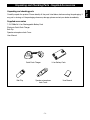
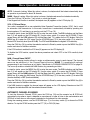
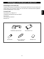
Unpacking and checking parts
Carefully unpack the product. Please identify all the parts listed below, before wasting the packaging. If
any part is missing or if the packaging shows any damage, please contact your dealer immediately.
Supplied accessories
7.4V 1200mAh Li-Ion Rechargeable Battery Pack
Electronic Quick Desk Charger
Belt Clip
Speaker-microphone Jack Cover
User Manual
English
Quick Desk Charger Li-Ion Battery Pack
Belt Clip
MI
C
Speaker-microphone
Jack Cover
User Manual

Preliminary Steps
- 4 -
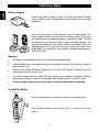
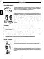
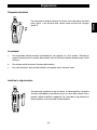
Battery charging
Connect the 230VAC adaptor charger to the desk type battery charger
and to a 230VAC outlet. The Red Led will flash to confirm that the charger
is powered.
Insert the empty battery or the transceiver with the battery pack in the
battery charger. Please make sure that the charging contacts of the radio
are connected with the charging contacts of the charger cradle. The Red
Led will light then the device is ready to begin the charging process. The
charging time depends on the battery condition and capacity. When the
charging process has finished, the Led lights in Green color. Remove the
battery pack or the transceiver from the battery charger and disconnect it
from the AC outlet.
Warning !
The battery is supplied empty and it has to be fully recharged before use.
Some complete cycles of charge/discharge will be necessary in order for the battery to reach a
peak efficiency level.
Please do not charge the battery again when it has just been charged. Otherwise, you may
damage the battery or reduce its life.
The battery charger does not switch OFF automatically when charging is complete, therefore
please remove battery or radio from the charger cradle and disconnect it from the AC outlet.
Do not recharge battery for more than 8 hours, in order to avoid battery overheating.
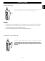
To install the battery
Place the battery pack on the radio as showed in the drawing (item 1).
Push the battery pack forward (item 2) until it is locked on the radio
(item 3).
1
2
3
English

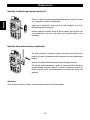
To remove the battery
To remove the battery pack, press the battery lock on the radio (item 1) and
push back the battery pack, as showed in the drawing (item 2).
Warning !
Please do not waste used batteries into the environment and do not trash them with the common
garbage. Please use the dedicated case for the collection of used up batteries at your supplier.
Do not attempt to open or remove the battery casing.
Do not short the battery terminals or throw the used batteries into fire.
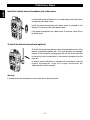
To install / to remove the belt clip
If necessary, attach the belt clip to the tranceiver, making it slide along the
fit runner placed on the rear side of the battery untill the lock will hook. To
remove the belt clip press the lock and slide the belt clip away from
the battery.
Preliminary Steps
- 5 -
2
1
English

- 6 -
Preliminary Steps
English
Install the external earset-microphone jack rubber cover.
If an external earset-microphone is not used, please install the earset-
microphone jack rubber cover.
Install the earset-microphone jack rubber cover as showed on the
drawing. FIx the cover with the supplied screw.
If the earset-microphone jack rubber cover is removed, radio will not
be splash proof.
To install the external microphone (optional)
To install the external microphone, remove the protection cover of the
external microphone/speaker jack. This cover ensures the watertight
integrity of the transceiver (spray-guard) that will not be ensured after
its removing. Insert the connector of the external microphone into the
right jack.
In order to avoid mulfunction or damage to the transceiver, use only
original microphones. Using non original accessories will
authomatically void the warranty.
Warning !
If an external earset-microphone is used, radio will not be splash proof.

Getting Acquainted with the Product
- 7 -
English
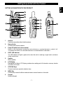
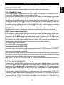
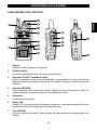
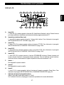
GETTING ACQUAINTED WITH THE PRODUCT
1. Antenna
Fixed non removable rubber flexible antenna.
2. Rotary Switch
Channels and functions selector.
3. Power ON switch and volume control
Switch on the transceiver turning the knob clockwise or counterclockwise to switch it off.
To increase the volume, turn the knob clockwise or counterclockwise to decrease it.
4. RX/TX LED Indicator
The LED indicator will light in green colour when the radio is receiving a signal and in red colour
during transmission.
5. Speaker
Built-in speaker.
6. LCD Display
Backlighted Dot Matrix LCD Display, provides clear reading and full information on every function
and status of the radio
7. UP/DOWN Keys
Channels and menu operation selection keys.
8. MENU Key
Function key to enter the Menu mode and access several functions of the radio.
9. Keypad
Numeric Keypad.
1
10
11
3
2
5
6
9
8
7
4
12
13
14
15
PT
T
16
17

- 8 -
Getting Acquainted with the Product
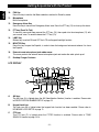
10. FUN Key
Press this key to confirm the Menu selections and exit to Stand-by mode.
11. Microphone
Built-in microphone.
12. Emergency Alarm Key
Press this key to transmit an Emergency Alarm tone. Press the PTT key (13) to close up the alarm.
13. PTT key (Push-To-Talk)
To transmit, press and keep pressed the PTT key (13), then speak into the microphone (11) with
your normal voice. To receive release the PTT key (13).
14. LAMP Key
Rubber key to switch ON and OFF the LCD and keypad backlight function.
15. MONITOR Key
Press this key to open the Squelch, in order to hear the background noise and release it to close
the Squelch.
16. External earset-microphone jack rubber cover
This cover protects the external earset-microphone jack and makes the radio splash proof.
17. Desktop Charger Contacts
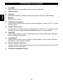
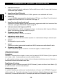
A. ANI Icon
The ANI Icon (A) is lighted when the ANI (Identification Number) function is enables. Please refer
to IDENTIFICATION NUMBER SETUP at page 15.
B. Keypad Lock Icon
The Lock icon (B) is lighted when the keypad lock function has been enabled. Please refer to
KEYBOARD LOCK SETUP at page 11.
C. CTS Icon
The CTS Icon (C) is lighted when the CTCSS function is enabled. Please refer to TONE
SQUELCH function at page 13-14.
English
A CB E GF HD
QR P OST
I
L
N
M
U
LCD DISPLAY

- 9 -
Getting Acquainted with the Product
English
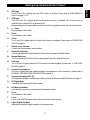
D. DCS Icon
The DCS Icon (D) is lighted when the DCS function is enabled. Please refer to TONE SQUELCH
function at page 13-14.
E. SCR Icon
The SCR Icon (E) is lighted when the Scrambler function is enabled. This function may be
enabled with the optional PC programming kit.
Before enabling this function, please make sure that local regulations allow the use of this device.
F.
+ -
Icons
Not available on this model.
G. R Icon
Not available on this model.
H. S Icon
The S Icon (H) is lighted when the Power Save function is enabled. Please refer to POWER SAVE
SETUP at page 14.
I. Battery Level Indicator
It shows the current battery level condition.
L. Numerical Indication
It shows the selected Channel Number and the function number in the Menu Mode.
M. Narrow Band Icon
This icon shows the 12.5KHz channel spacing and it cannot be modified by user.
N. VOX Icon
The VOX icon is lighted when the VOX function has been enabled. Please refer to VOX LEVEL
SETUP at page 12.
O. Channel Scanning Icon
This Icon is lighed when the selected channel is programmed to the scanning list. Please refer to
CHANNEL SCANNING ADDITION/DELETION at page 11.
P. Frequency Reading (25-5-75).
The frequency reading is available only in Memory Mode. Please refer to MODE function at page 13.
Q. RF Digital Meter
It indicates the transmitter RF output power.
R. Dot Matrix Indication
It provides full information on channel and all enabled functions.
S. H Icon
Not available on this model.
T. L Icon
It shows the 0.5W RF output power and it cannot be modified by user.
U. Signal Digital Bar Meter
Indicates the received signal strenght in the receive mode.

- 10 -
Getting Started - Menu Operation
English
GETTING STARTED
Power ON
Switch on the transceiver turning the Power/Volume knob (3) clockwise until you hear a click, the
transceiver now is in stand-by mode.
Volume adjustment
To adjust the volume, turn the volume knob (3) while using the MONITOR key (15) to listen to the
background noise of the channels.
Channel selection
Select the desired channel, using the UP/DOWN keys (7) or the channels selector (2). You may also
select the desired channel by entering the channel number directly on the numeric keypad (9). For
example, type 001 to select the channel numer 01.
Transmission
In order to transmit, press the PTT key (13) and speak with your normal voice, keeping the microphone
at about 4 cm from your mouth. The LED indicator (4) will light in red color. Release the PTT Key (13) at
the end of transmission.
Receiving
Release the PTT (13) key and properly adjusting volume, you will be able to receive the incoming signals.
When receiving a signal, the LED indicator (4) will light in green colour.
MENU OPERATION
In stand-by status, press MENU key (8) to enter the menu. The numerical indication (L) will show the
selected menu item.
Uses the UP/DOWN (7) keys or the rotary switch (2) to choose menu items and press the FUN Key
(10) to confirm the selections and exit to Stand-by mode.
1. Menu function sequence
SQL (Squelch setup) ---> LED (backlight setup) ---> BEP (keypad tone ON/OFF) ---> SCN (channel
scanning add or remove) ---> KY (keypad lock setup) ---> VOX (VOX sensitivity setup) ---> NAM
(channel naming ON/OFF).
2. Key Function in the Menu Mode
MENU Key (8) : enter the menu mode
UP/DOWN Keys (7) or CHANNELS SELECTOR (2): choose menu items
FUN Key (10) : confirm item choice or parameter and exit to Stand-by mode
SQL : Squelch Level Setup
In stand-by status, press the MENU Key (8) to enter the menu mode. The SQL indication (R) and the
Menu item 1 (L) will appear on the LCD display (6). Press the MENU key (8) to enter the Squelch setup.
The Squelch level will flash on the LCD display. Use the UP/DOWN keys (7) or the rotary switch (2) to
choose the desired squelch level from 00 (Squelch opening) to 09. If level 00 is selected, Squelch will be
open and you will hear the background noise. Press the FUN Key (10) to confirm the selection and exit to
Stand-by mode or press the MENU Key (8) to confirm and return to the Menu selection.

Menu Operation
- 11 -
English
LED : Backlight Setup
In stand-by status, press the MENU Key (8) to enter the menu mode. The SQL indication and the Menu
item 1 (L) will appear on the LCD display (6). Use the rotary switch (2) or press the UP/DOWN (7) keys
several times until the LED indication (R) and the Menu item 2 (L) appear on the LCD display. Press the
MENU key (8) to enter the LED setup. The LED selected option (AUT, ON or OFF) will flash on the LCD
display. Use the UP/DOWN keys (7) or the rotary switch (2) to choose the desired option as follow :
AUT : When this option is selected, the LCD display backlight will be turned on once you press a key.
ON : When this option is chosen, the LCD display backlight will be turned ON automatically.
OFF : When this option is chosen, the LCD display backlight will be turned OFF automatically.
Press the FUN Key (10) to confirm the selection and exit to Stand-by mode or press the MENU Key (8) to
confirm and return to the Menu selection.
However you can turn ON or OFF the LCD backlight anytime, by pressing the LAMP key (14).
BEP : Keypad Tone Setup
When a key is pressed, a beep tone is heard to confirm your command. The user may enable or disable
this keypad program tone. In stand-by status, press the MENU Key (8) to enter the menu mode. The SQL
indication and the Menu item 1 (L) will appear on the LCD display (6). Use the rotary switch (2) or press
the UP/DOWN (7) keys several times until the BEP indication (R) and the Menu item 3 (L) appear on the
LCD display. Press the MENU key (8) to enter the BEP setup. Use the UP/DOWN keys (7) or the rotary
switch (2) to select ON (Keypad tone enabled) or OFF (Keypad tone disabled). Press the FUN Key (10) to
confirm the selection and exit to Stand-by mode or press the MENU Key (8) to confirm and return to the
Menu selection.
SCN : Channel Scanning ADDITION / DELETION Setup
Select the channel to be added to the scanning list, using the UP/DOWN keys (7) or the channels
selector (2). In stand-by status, press the MENU Key (8) to enter the menu mode. The SQL indication and
the Menu item 1 (L) will appear on the LCD display (6). Use the rotary switch (2) or press the UP/DOWN
(7) keys several times until the SCNADD (or SCNDEL) indication (R) and the Menu item 4 (L) appear on
the LCD display. Press the MENU key (8) to enter the SCN setup. Use the UP/DOWN keys (7) or the
rotary switch (2) to choose the following options :
ADD : the selected channel will be added to the scanning list; the Channel Scanning Icon (O) will appear on
the LCD display (6).
DEL : the selected channel will be removed from the scanning list; the Channel Scanning Icon (O) will
disappear from the LCD display (6).
Press the FUN Key (10) to confirm the selection and exit to Stand-by mode or press the MENU Key (8) to
confirm and return to the Menu selection.
KY : Keypad Lock setup
In stand-by status, press MENU Key (8) to enter the menu mode. The SQL indication and the Menu item 1
(L) will appear on the LCD display (6). Use the rotary switch (2) or press the UP/DOWN (7) keys several
times until the KY indication (R) and the Menu item 5 (L) appear on the LCD display. Press the MENU key
(8) to enter the KY setup. Use the UP/DOWN keys (7) or the rotary switch(2) to choose the following
options :

AUTO : Automatic Locking. When this option is chosen, the keyboard will be locked automatically when
no operation is performed for about 30 seconds.
MANU : Manual Locking. When this option is chosen, the keyboard cannot be locked automatically.
Press the FUN key (10) and the * key to lock or unlock the keypad.
If the Keypad lock function is enabled, the keylock icon (B) appears on the LCD display (5).
VOX : VOX Level Setup
Your radio is equipped with a user selectable Voice Operated Transmitter function (VOX), that is used
for automatic voice transmission. In this mode, transmission is automatically initiated by speaking into
the microphone (11) and there is no need to push the PTT key (13).
In stand-by status, press the MENU Key (8) to enter the menu mode. The SQL indication and the Menu
item 1 (L) will appear on the LCD display (6). Use the rotary switch (2) or press the UP/DOWN (7) keys
several times until the VOX indication (R) and the Menu item 7 (L) appear on the LCD display. Press the
MENU key (8) to enter the VOX setup. Use the UP/DOWN keys (7) or the rotary switch (2) to select the
desired VOX sensitivity level (from 01 to 09). The VOX level 09 indicates the highest VOX sensitivity.
Press the FUN Key (10) to confirm the selection and exit to Stand-by mode or press the MENU Key (8) to
confirm and return to the Menu selection.
If the VOX function is enabled, the VOX icon (N) appears on the LCD display (6).
To disable the VOX function, repeat the above procedure and select OFF in the VOX sensitivity level
selection.
NAM : Channel Name ON/OFF
The Channel Naming function allows to assign an alphanumeric name to each channel. The channel
name can be edited only if the Channel Naming function (NAME ?) is enabled with optional
programming kit and it can have up to 6 digits. Please refer to CHANNEL NAMING SETUP at page 16.
The user may enable or disable the NAM function, by proceeding as follow :
in stand-by status, press the MENU Key (8) to enter the menu mode. The SQL indication and the Menu
item 1 (L) will appear on the LCD display (5). Use the rotary switch (2) or press the UP/DOWN (7) keys
several times until the NAM indication (R) and the Menu item 8 (L) appear on the LCD display. Press the
MENU key (8) to enter the NAM setup. Use the UP/DOWN keys (7) or the rotary switch (2) to select ON
(function enabled) or OFF (function disabled).
Press the FUN Key (10) to confirm the selection and exit to Stand-by mode or press the MENU Key (8) to
confirm and return to the Menu selection.
If the NAM function is enabled, the channel name will appear on the LCD display. Otherwise on the LCD
will appear the indication CH- and the selected channel number.
AUTOMATIC CHANNEL SCANNING
To start the Automatic Channel SCAN, press the FUN key (10) and the numeric key 0. SCAN will
automatically stop when a signal is detected on one channel, in order to listen to the communication and
SCAN will re-start when no more signal is detected on that channel for a few seconds.
During the scanning process, use the UP/DOWN keys (7) or the rotary switch (2) to choose the SCAN
direction. To stop the SCAN function press the PTT (13) or FUN (10) keys.
Menu Operation - Automatic Channel Scanning
- 12 -
English

- 13 -
Advanced Functions
ADVANCED FUNCTIONS
These additional functions may be enabled only by using the optional programming kit.
SCR : SCRAMBLER Function
You can enjoy privacy of communication within your group, by enabling the SCRAMBLER function.
To enable the SCRAMBLER function please proceed as follows :
In stand-by status, press the MENU Key (8) to enter the menu mode. The SQL indication and the Menu
item 1 (L) will appear on the LCD display (6). Use the rotary switch (2) or press the UP/DOWN (7) keys
several times until the SCR indication (R) and the Menu item 6 (L) appear on the LCD display. Press the
MENU key (8) to enter the SCR setup. Use the UP/DOWN keys (7) or the rotary switch (2) to select ON
(Scrambler function enabled) or OFF (Scrambler function disabled). Press the FUN Key (10) to confirm
the selection and exit to Stand-by mode or press the MENU Key (8) to confirm and return to the Menu
selection. If the SCRAMBLER function is enabled, the SCR icon (E) appears on the LCD display.
WARNING ! This function may be enabled with the optional PC programming kit.
Before enabling this function, please make sure that local regulations allow the use of this device.
MODE : Channel / Memory Mode Switch
In stand-by status, press the MENU Key (8) to enter the menu mode. The SQL indication and the Menu
item 1 (L) will appear on the LCD display (6). Use the rotary switch (2) or press the UP/DOWN (7) keys
several times until the MODE indication (R) and the Menu item 10 (L) appear on the LCD display. Press
the MENU key (8) to enter the MODE setup. Use the UP/DOWN keys (7) or the rotary switch (2) to select
CH (Channel mode) or MR (Memory Mode). Press the FUN Key (10) to confirm the selection and exit to
Stand-by mode or press the MENU Key (8) to confirm and return to the Menu selection.
CH : Channel Mode / Channel Naming
MR : Memory Mode / Full frequency readout
Tone Squelch Function (CTCSS) / (DCS)
Any channel may be associated to a programmed private protection CTCSS/DCS tone. A CTCSS/DCS
tone is a sub audible tone which allows to cut off and therefore not to listen to signals transmitted from
other users on the same operating channel.
When you receive a signal which has a tone different from the one which has been programmed on
your radio, you will not listen to this signal. For the same reason, your outgoing messages can only be
received by other radios which have the same tone as yours on that channel.
Note : Even if the use of a CTCSS/DCS tone will protect you from receiving unwanted signals, the
privacy of your transmissions is not guaranteed.
R : CTCSS / DCS RECEIVER SETUP
In stand-by status, press the MENU Key (8) to enter the menu mode. The SQL indication and the Menu
item 1 (L) will appear on the LCD display (6). Use the rotary switch (2) or press the UP/DOWN (7) keys
several times until the R indication (R) and the Menu item 11 (L) appear on the LCD display. Press the
MENU key (8) to enter the R setup. Press the FUN Key (10) to switch between the CTCSS tone selection
and DCS tone selection. In the DCS tone selection, the LCD display will show the indication RD and the
DCS tone number. Use the UP/DOWN keys (7) or the rotary switch (2) to select the desired CTCSS / DCS
Tone number or select OFF to disable the function. Press the MONITOR Key (15) to confirm the selection
and exit to Stand-by mode or press the MENU Key (8) to confirm and return to the Menu selection. In
receiving mode, if the CTCSS / DCS functions are enabled, the CTCSS Icon (C) or DCS Icon (D) will
appear on the LCD display (6).
English

- 14 -
Advanced Functions
T : CTCSS / DCS TRANSMITTER SETUP
In stand-by status, press the MENU Key (8) to enter the menu mode. The SQL indication and the Menu
item 1 (L) will appear on the LCD display (6). Use the rotary switch (2) or press the UP/DOWN (7) keys
several times until the T indication (R) and the Menu item 12 (L) appear on the LCD display. Press the
MENU key (8) to enter the T setup. Press the FUN Key (10) to switch between the CTCSS tone selection
and DCS tone selection. In the DCS tone selection, the LCD display will show the indication TD and the
DCS tone number. Use the UP/DOWN keys (7) or the rotary switch (2) to select the desired CTCSS / DCS
Tone number or select OFF to disable the function. Press the MONITOR Key (15) to confirm the selection
and exit to Stand-by mode or press the MENU Key (8) to confirm and return to the Menu selection. In
transmitting mode, if the CTCSS / DCS functions are enabled, the CTCSS Icon (C) or DCS Icon (D) will
appear on the LCD display (6).
C : CTCSS / DCS SETUP (RECEIVING AND TRANSMITTING MODES)
In stand-by status, press the MENU Key (8) to enter the menu mode. The SQL indication and the Menu
item 1 (L) will appear on the LCD display (6). Use the rotary switch (2) or press the UP/DOWN (7) keys
several times until the C indication (R) and the Menu item 13 (L) appear on the LCD display. Press the
MENU key (8) to enter the C setup. Press the FUN Key (10) to switch between the CTCSS tone selection
and DCS tone selection. In the DCS tone selection, the LCD display will show the indication CD and the
DCS tone number. Use the UP/DOWN keys (7) or the rotary switch (2) to select the desired CTCSS / DCS
Tone number or select OFF to disable the function. Press the MONITOR Key (15) to confirm the selection
and exit to Stand-by mode or press the MENU Key (8) to confirm and return to the Menu selection. If the
CTCSS / DCS functions are enabled, the CTCSS Icon (C) or DCS Icon (D) will appear on the LCD display
(6).
SAV : Power Save Setup
This function reduces the battery consumption when no signal is received or when no operation is
performed (it means when no key is pressed, no switch is turned on/off). The user may enable or
disable this function. In stand-by status, press the MENU Key (8) to enter the menu mode. The SQL
indication and the Menu item 1 (L) will appear on the LCD display (6). Use the rotary switch (2) or press
the UP/DOWN (7) keys several times until the SAV indication (R) and the Menu item 14 (L) appear on
the LCD display. Press the MENU key (8) to enter the SAV setup. Use the UP/DOWN keys (7) or the
rotary switch (2) to select ON (Power Save enabled) or OFF (Power Save disabled). Press the FUN
Key (10) to confirm the selection and exit to Stand-by mode or press the MENU Key (8) to confirm and
return to the Menu selection.
SCAN : Automatic Scanning Setup
In stand-by status, press the MENU Key (8) to enter the menu mode. The SQL indication and the Menu
item 1 (L) will appear on the LCD display (6). Use the rotary switch (2) or press the UP/DOWN (7) keys
several times until the SCAN indication (R) and the Menu item 15 (L) appear on the LCD display. Press
the MENU key (8) to enter the SCN setup. Use the UP/DOWN keys (7) or the rotary switch (2) to select
CO (Carrier Scan) or TO (Time Scan). Press the FUN Key (10) to confirm the selection and exit to Stand-
by mode or press the MENU Key (8) to confirm and return to the Menu selection.
To start the Automatic Channel SCAN, press the FUN key (10) and the numeric key 0.
CO (Carrier Scan) : If this option is selected, SCAN will automatically stop when a signal is detected on
one channel, in order to listen to the communication and SCAN will re-start when no more signal is
detected on that channel for a few seconds.
English

- 15 -
Advanced Functions
TO (Time Scan) : If this option is selected, SCAN will automatically stop when a signal is detected on one
channel, and re-start automatically after a few seconds.
During the scanning process, press the UP/DOWN keys (7) or the rotary switch (2) to choose the SCAN
direction. To stop the SCAN function press the PTT (13) or FUN (10) keys.
TOT : Time-Out-Timer Setup
This function has two purposes :
1. to allow, after a set time, to listen to other urgent calls.
2. avoid to transmit for an endless time, in order to prevent overheating or damage to the
transceiver. After a programmable time of 30-240 seconds of uninterrupted transmission, the
transceiver automatically stops the transmission emitting a warning tone (pre-set function). To stop the
warning tone, release the PTT key (13). To restart the transmission, press again the PTT key (13).
To set up this function, in stand-by status, press the MENU Key (8) to enter the menu mode. The SQL
indication and the Menu item 1 (L) will appear on the LCD display (6). Use the rotary switch (2) or press
the UP/DOWN (7) keys several times until the TOT indication (R) and the Menu item 16 (L) appear on the
LCD display. Press the MENU key (8) to enter the TOT setup. Use the UP/DOWN keys (7) or the rotary
switch (2) to select the desired time from 30 to 240 seconds or select OFF to disable the function. Press
the FUN Key (8) to confirm the selection and exit to Stand-by mode or press the MENU Key (8) to confirm
and return to the Menu selection.
ANI : Identification Number Setup
In stand-by status, press the MENU Key (8) to enter the menu mode. The SQL indication and the Menu
item 1 (L) will appear on the LCD display (6). Use the rotary switch (2) or press the UP/DOWN (7) keys
several times until the ANI indication (R) and the Menu item 17 (L) appear on the LCD display. Press the
MENU key (8) to enter the ANI setup. Use the UP/DOWN keys (7) or the rotary switch (2) to select ON
(function enabled) or OFF (function disabled). Press the FUN Key (10) to confirm the selection and exit to
Stand-by mode or press the MENU Key (8) to confirm and return to the Menu selection.
BUS : Busy Channel Lockout Setup
In stand-by status, press the MENU Key (8) to enter the menu mode. The SQL indication and the Menu
item 1 (L) will appear on the LCD display (6). Use the rotary switch (2) or press the UP/DOWN (7) keys
several times until the BUS indication (R) and the Menu item 19 (L) appear on the LCD display. Press the
MENU key (8) to enter the BUS setup. Use the UP/DOWN keys (7) or the rotary switch (2) to choose the
desired option as follow :
CAR : when the radio is receiving a signal, you can' t transmit at the same time.
QDT : when the radio is receiving a signal with the same CTCSS/DCS code, you can' t transmit at the
same time.
OFF : the function is disabled.
Press the FUN Key (10) to confirm the selection and exit to Stand-by mode or press the MENU Key (8) to
confirm and return to the Menu selection.
English

Advanced Functions - Menu Shortcut Keys
- 16 -
NAME ? : Channel Naming Setup
In stand-by status, press the MENU Key (8) to enter the menu mode. The SQL indication and the Menu
item 1 (L) will appear on the LCD display (6). Use the rotary switch (2) or press the UP/DOWN (7) keys
several times until the NAME ? indication (R) and the Menu item 20 (L) appear on the LCD display. Press
the MENU key (8) to edit the channel name; the first digit will blink on the LCD display. Use the UP/DOWN
keys (7) or the rotary switch (2) to select the desired number or letter of the flashing digit and press the
MONITOR key (15) to edit the next digit. The selected digit will start flashing.
Press the FUN Key (10) to confirm the selection and exit to Stand-by mode or press the MENU Key (8) to
confirm and return to the Menu selection.
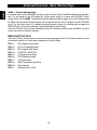
MENU SHORTCUT KEYS
Press the FUN key (10) then press a numeric key to enter appropriate items. This shortcut function is same
as the menu mode, but it is more easy to operate the Two Way Radio.
FUN + 1 SQL (Squelch) Level Setup
FUN + 2 LED (LCD backlight) Setup
FUN + 3 BEP (Keypad Tone) Setup
FUN + 4 SCAN ADD / DELETION
FUN + 5 KY (Keypad Lock) Setup
FUN + 6 SCR (Scrambler) Setup
FUN + 7 VOX Level Setup
FUN + 8 NAM (Channel Naming) Setup
FUN + 0 Start Scanning
FUN +
*
Keyboard Lock / Unlock
English

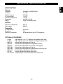
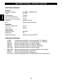
SPECIFICATIONS
General
Frequency 446.00625 - 446.09375 MHz
Channels 16 / 199
Channel spacing 12.5 KHz
DC input voltage 7.4 VDC
Operating temperature -20/+55°
Dimensions mm 58 x 124 x 38
Weight 230 gr. (with battery pack)
Receiver
Sensitivity (12dB Sinad) 0.25 µV
Audio output 500mW
Transmitter
RF output power 0.5W ERP
Modulation FM
Spurious & Harmonics in compliance with the R&TTE regulations
OPTIONAL ACCESSORIES
- LN-865 High capacity Li-Ion 7.2V 1800mAh rechargeable battery pack
- LP-865 High capacity Li-Poly 7.4V 1800mAh rechargeable battery pack
- KME-315 External Earset-Microphone with tie clip
- KME-614 External Earset-Microphone with adjustable ear hook
- KME-801 External Earset-Microphone for security and bodyguard
- KME-100A External Earset-Microphone with tie clip
- KME-200A External Earset-Microphone with flexible boom mic and tie clip
- KME-H115 External Speaker-Microphone (light duty)
- KST-301 External Speaker-Microphone (heavy duty)
- CDLS-HTHX Programming Kit (PC interface cable and software CD)
- 17 -
Specifications - Optional Accessories
English

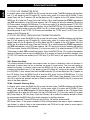
Frequency / Channels Programming - User Information
- 18 -
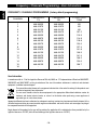
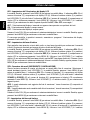
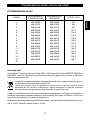
CHANNEL
FREQUENCY
TX
FREQUENCY
RX
CTCSS / DCS
TONE
1
2
3
4
5
6
7
8
9
10
11
12
13
14
15
16
446.00625
446.01875
446.03125
446.04375
446.05625
446.06875
446.08125
446.09375
446.00625
446.01875
446.03125
446.04375
446.05625
446.06875
446.08125
-
446.00625
446.01875
446.03125
446.04375
446.05625
446.06875
446.08125
446.09375
446.00625
446.01875
446.03125
446.04375
446.05625
446.06875
446.08125
-
NO
NO
NO
107.2
110.9
114.8
118.8
123.0
127.3
131.8
136.5
141.3
146.2
123.0
156.7
-
FREQUENCY / CHANNELS PROGRAMMING (factory default programming)
User Information
in accordance with art. 13 of the Legislative Decree of 25th July 2005, no. 15 ”Implementation of Directives 2002/95/EC,
2002/96/EC and 2003/108/EC, relative to reduction of the use of hazardous substances in electrical and electronic
equipment, in addition to waste disposal”.
The crossed bin symbol shown on the equipment indicates that at the end of its working life the product must
be collected separately from other waste.
The user must therefore take the above equipment to the appropriate differentiated collection centres for
electronic and electro technical waste, or return it to the dealer when purchasing a new appliance of
equivalent type, in a ratio of one to one.
Appropriate differentiated waste collection for subsequent recycling, treatment and environment-friendly disposal of the
discarded equipment helps to prevent possible negative environmental and health effects and encourages recycling of
the component materials of the equipment.
Illegal disposal of the product by the user will be punished by application of the administrative fines provided for by the
legislative decree no. 22/1997 (article 50 and following of the legislative decree no. 22/1997).
English
La pagina si sta caricando...
La pagina si sta caricando...
La pagina si sta caricando...
La pagina si sta caricando...
La pagina si sta caricando...
La pagina si sta caricando...
La pagina si sta caricando...
La pagina si sta caricando...
La pagina si sta caricando...
La pagina si sta caricando...
La pagina si sta caricando...
La pagina si sta caricando...
La pagina si sta caricando...
La pagina si sta caricando...
La pagina si sta caricando...
La pagina si sta caricando...
La pagina si sta caricando...
La pagina si sta caricando...
La pagina si sta caricando...
La pagina si sta caricando...
La pagina si sta caricando...
La pagina si sta caricando...
La pagina si sta caricando...
La pagina si sta caricando...
-
 1
1
-
 2
2
-
 3
3
-
 4
4
-
 5
5
-
 6
6
-
 7
7
-
 8
8
-
 9
9
-
 10
10
-
 11
11
-
 12
12
-
 13
13
-
 14
14
-
 15
15
-
 16
16
-
 17
17
-
 18
18
-
 19
19
-
 20
20
-
 21
21
-
 22
22
-
 23
23
-
 24
24
-
 25
25
-
 26
26
-
 27
27
-
 28
28
-
 29
29
-
 30
30
-
 31
31
-
 32
32
-
 33
33
-
 34
34
-
 35
35
-
 36
36
-
 37
37
-
 38
38
-
 39
39
-
 40
40
-
 41
41
-
 42
42
-
 43
43
-
 44
44


INTEK HX-174S Manuale del proprietario
- Categoria
- Radio a due vie
- Tipo
- Manuale del proprietario
- Questo manuale è adatto anche per
in altre lingue
- English: INTEK HX-174S Owner's manual
Documenti correlati
-
INTEK MT-446EX Manuale del proprietario
-
-
-
-
-
-
-
-
-
INTEK MT-5050 Manuale del proprietario
