ProLights ECLFRJPTW Manuale utente
- Categoria
- Proiettori
- Tipo
- Manuale utente

ECLFRJPTW
POLE OPERATED FRESNEL PROJECTOR
USER MANUAL
MANUALE UTENTE
EN - IT

All rights reserved by Music & Lights S.r.l. No part of this instruction manual may be
reproduced in any form or by any means for any commercial use.
In order to improve the quality of products, Music&Lights S.r.l. reserves the right to modify the
characteristics stated in this instruction manual at any time and without prior notice.
All revisions and updates are available in the ‘manuals’ section on site www.musiclights.it
REV.01-04/20

1
ECLFRJPTW
Packing content
• ECLFRJPTW
• ECLIPSEFRSJBD
• ECLFRSPG
• Power cable
• User manual
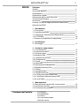
TABLE OF CONTENTS
Safety
SymbolsSymbols
General instructionsGeneral instructions
ApprovalsApprovals
Fire preventionFire prevention
Electric shock preventionElectric shock prevention
Photobiological safetyPhotobiological safety
WarningsWarnings
Waste Electrical and Electronic Equipment Directive Waste Electrical and Electronic Equipment Directive
(WEEE)(WEEE)
1 Introduction
1. 1 Description and specications1. 1 Description and specications
1. 2 Technical specication1. 2 Technical specication
1. 3 Operating elements and connections1. 3 Operating elements and connections
1. 4 ECLFRSJBP41. 4 ECLFRSJBP4
1. 5 operating elements and connections1. 5 operating elements and connections
2 Installation
2. 1 Mounting2. 1 Mounting
3 Functions and settings
3. 1 Operation3. 1 Operation
3. 2 Basic3. 2 Basic
3. 3 Menu structure3. 3 Menu structure
3. 4 DMX mode3. 4 DMX mode
3. 5 DMX conguration3. 5 DMX conguration
3. 6 Linking3. 6 Linking
3. 7 Screen3. 7 Screen
3. 8 Advanced3. 8 Advanced
3. 9 Information3. 9 Information
3. 10 Master/Slave3. 10 Master/Slave
3. 11 Eects3. 11 Eects
3. 12 Static mode3. 12 Static mode
3. 13 Manual mode3. 13 Manual mode
3. 14 Connection of the DMX line3. 14 Connection of the DMX line
3. 15 Construction of the DMX termination3. 15 Construction of the DMX termination
3. 16 Channels DMX3. 16 Channels DMX
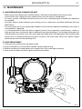
4 Maintenance
4. 1 Maintenance and cleaning the unit4. 1 Maintenance and cleaning the unit
4. 2 Fuse replacement4. 2 Fuse replacement
4. 3 Trouble shooting4. 3 Trouble shooting
2
3
3
3
3
4
4
4
5
7
7
8
8
10
11
11
12
15
16
16
16
16
17
17
17
17
18
19
19
20
27
27
28

ECLFRJPTW
2
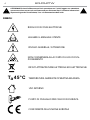
WARNING! Before carrying out any operations with the unit, carefully read this instruction
manual and keep it with cure for future reference. It contains important information about
the installation, usage and maintenance of the unit.
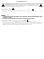
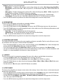
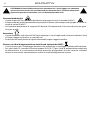
T 45°C
a
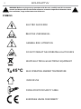
ELECTRIC SHOCK RISK
READ THE USER MANUAL
GENERAL RISK / ATTENTION
DO NOT STARE AT THE OPERATING LIGHT SOURCE
WASTE ELECTRICAL & ELECTRONIC EQUIPMENT
MAX OPERATING AMBIENT TEMPERATURE
INDOOR USE
FIXING POINT FOR SAFETY CABLE
EUROPEAN UNION CONFORMITY
SYMBOLS

3
ECLFRJPTW
SAFETY
General instruction
• This unit is not for home use, only professional applications.
• The connection to the main network of electric distribution must be carried out by a qualied electrical
installer.
• Before starting any maintenance work or cleaning the projector, cut o power from the main supply.
• Connection must be made to a power supply system tted with ecient earthing (Class I appliance ac-
cording to standard EN 60598-1). It is, moreover, recommended to protect the supply lines of the units
from indirect contact and/or shorting to earth by using appropriately sized residual current devices.
• Do not modify the unit in any way not described in this manual or install parts other than the original
Music & Lights parts. Do not apply lters, lenses or other materials on lenses or other optical compo-
nents. Use only accessories approved by Music & Lights.
• If this device will be operated in any way dierent to the one described in this manual, it may suer
damage and the guarantee becomes void.
• We decline any liability deriving from improper use of the product.
Approvals
• The products referred to in this manual conform to the European Community Directives LVD (Low Volt-
age Directive) 2014/35 / EC, EMC (Electromagnetic Compatibility Directive) 2014/30 / EU, RoHS (Restric-
tion of Hazardous Substances Directive) 2011/65 / CE and are therefore marked with
.
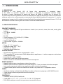
Fire prevention
• The minimum distance between the projector and the surrounding walls and ammable materials
must be greater than 50 cm and the ventilation openings must in no case be blocked.
• Replace a defective, blown or damaged fuse only with one of the same type. To replace the fuse, refer
to the “Maintenance” paragraph.
• Do not use the unit if the ambient temperature exceeds 45 ° C (122 ° F).
• The surface of the appliance can reach up to 50 ° C (158 ° F) during operation. Avoid contact with peo-
ple and materials.
• Make sure there is a free and unobstructed air ow around the appliance.
Electric shock prevention
• The unit is supplied with hazardous network voltage (230V~). Leave servicing to skilled personnel only.
Never make any modications on the unit not described in this instruction manual, otherwise you will
risk an electric shock.
• Disconnect power to the unit when not in use.
• Install the xture in a well ventilated place.
• Refer to any service operation not described in this manual to Music & Lights technical support.
• Isolate the unit immediately from the power supply if any gaskets, covers, cables or other components
are damaged, defective, deformed or showing signs of overheating. Do not reapply power until repairs
are complete. Before using the unit, check that all components and power distribution cables are in
perfect condition.Check that the frequency and voltage of the network correspond to the frequency
and voltage for which the unit is set up, indicated on the electrical data plate.
T 45°C
a
0,5 m
WARNING! Before carrying out any operations with the unit, carefully read this instruction
manual and keep it with cure for future reference. It contains important information about
the installation, usage and maintenance of the unit.

ECLFRJPTW
4
Photobiological safety
• This device is a product identied in risk group 2 according to EN 62471.
• Emits potentially dangerous optical radiation. It falls into the categories of the risk group according to
EN 62471.
• Do not look directly at the LED source during operation. It can be harmful to the eyes.
Warnings
• This device is rated IP20. It is not suitable for use in humid places. Never use the xture in places subject
to vibrations or bumps.
• Make certain that no inammable liquids, water or metal objects enter the xture.
Waste Electrical and Electronic Equipment Directive (WEEE)
• The unit, accessories and packaging should be sorted for environmetal-friendly recycling.
• For EC countries: according to the European Directive 2012/19/EC for Waste Electrical and Electronic
Equipment and its implementation into national right, luminaires that are no longer usable must be
collected separately and disposed of in an environmentally correct manner.
WARNING! Before carrying out any operations with the unit, carefully read this instruction
manual and keep it with cure for future reference. It contains important information about
the installation, usage and maintenance of the unit.

5
ECLFRJPTW
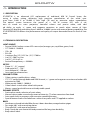
- 1 - INTRODUCTION
1.1 DESCRIPTION
ECLFRJPTW is an advanced LED replacement of traditional 650 W Fresnel lamps, fea-
turing 6 colour mixing delivering high precision reproduction of the white spec-
trum from 2.800 K to 10.000 K with high CRI and an extensive colour reproduction.
The optical system harnesses the power of a 130 W custom LED with 6 col-
ours to create an even projection, beautiful colours and precise white, with add-
ed ability to apply +/- green and magenta correction to match other sources of light.
Featuring HD dimming and tuning from 2.800 K to 10.000 K version with external battery capabilities, the
ECLIPSEFRESNELTW delivers the performance and quality of output demanded from this level of lumi-
naire.
1.2 TECHNICAL DESCRIPTION
LIGHT SOURCE
• Source:130 W 6 colour custom LEDs source (red, orange, cyan, royal blue, green, lime)
• CCT:2.800 K - 10.000 K
• CRI:> 90
• R9:> 90
• Luminous ux:(15°) 1’637 lm - (51°) 2’700 lm
• Lux:(15°) 2’067 lx @3 m
• Lux:(51°) 421 lx @3 m
• Source life expectancy: > 50.000 h
OPTICS
• Zoom:15 ° - 51 ° manual
• Field angle:26,7° - 75,6° °
• Lens diameter:6’’ - 150 mm
• Lens type:fresnel zoom lens
COLOUR SYSTEM
• Colour mixing: tunable white + colour
• CTC: CTC control through dedicated DMX channel, + / - green and magenta correction and amber shift
activation by DMX
• White presets:2.800 K - 10.000 K
• Colour wheel: virtual colour wheel with presets
• Macros: several pre-build macros with adjustable speed
DYNAMIC EFFECTS
• Static colour mode: selection of static colour
• Manual colour mode: manual adjustment of intensity, CT, colour correction from knob
• Auto mode: built-in programs with execution speed adjustment
• Special features:linear crossfade from a white to any color and CTO applied on colours
BODY
• Hardware on-board:included lter frame, 8 doors barndoor, omega bracket spigot
• Pan angle:360 ° with manual regulation
• Tilt angle:340 ° with manual regulation
• Body: sturdy die-cast aluminium body conceived for long-time durability
• Body colour: black

ECLFRJPTW
6
CONTROL
• Protocols: DMX512, RDM, local knob
• DMX channels:1 / 2 / 5 - 1 / 5 - 2 / 7 / 9 / 12 / 13 / 16 / 19 / 21 channel
• RDM: RDM ready for xture remote monitor and settings
• Display: black OLED high resolution display
• Firmware upgrade: yes, via USB - DMX interface (UPBOX1) not included
• Other: 16bit control of dimmer and colour
ELECTRONICS
• Dimmer: linear 0 ~ 100% electronic dimmer
• Dimmer curves:4 dierent dimming curves available
• Strobe / shutter:1 - 30 Hz, electronic
• Flicker: icker free frequency with adjustable PWM
• Selectable PWM: 600 ~ 25.000 Hz
ELECTRICAL
• Power supply: 100-240 V – 50/60 Hz
• Power consumption (at 230 V):107 W
• Power consumption (at 120 V):111 W
• Output (at 230 V):23 units on a single power line
• Output (at 120 V):12 units on a single power line
• Power factor:pF 0,99 @120 V - pF 0,95 @230 V
BATTERY
• Battery:24 - 34 V 4400 mAh (optional) external battery
• Re-charge connection: XLR 4p
PHYSICAL
• Cooling: combination of heat pipe cooling system and low noise fan
• Sospension and xing: hanging bracket suitable for safe hanging and positioning
• Signal connection: Amphenol XLR 5p IN/OUT connectors
• Power connection: Neutrik powerCON TRUE1 IN/OUT connectors
• IP rating:20
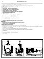
• Dimensions (WxHxD):297x497x260 mm
• Weight: 7.6 kg
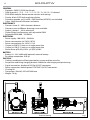
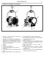
Technical drawing Fig.1

7
ECLFRJPTW
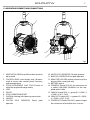
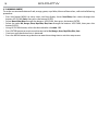
1.3 OPERATING ELEMENTS AND CONNECTIONS
Fig.2
5
6
7
3
4
2
1
13
10
9
14
15
16
17
8
11
12
1. VENTILATION GRID for air ow outlet not to be
obstructed.
2. CONTROL PANEL with display and 3 buttons
used to access the control panel functions
and manage them.
3. ZOOM ADJUSTMENT AND FOCUS knob to
zoom the projected image clearly.
4. LENS
5. SPIGOT
6. POLE OPERATED BRACKET
7. GUIDE for locking and releasing accessories.
8. HANDLE
9. YELLOW POLE OPERATOR: Zoom pole
operator.
10. WHITE POLE OPERATOR: Tilt pole operator.
11. BLUE POLE OPERATOR: Pan pole operator.
12. MAIN FUSE HOLDER: replace a burnt-out fuse
by one of the same type only
13. BATTERY 4pin-in.
14. POWER IN (PowerCON IN): for connection to
a socket (100-240V~/50-60Hz) via the sup-
plied mains cable.
15. DMX IN (5-pole XLR): 1 = ground, 2 = DMX-, 3
= DMX+, 4 N/C, 5 N/C.
16. DMX OUT (5-pole XLR): 1 = ground, 2 = DMX-,
3 = DMX+, 4 N/C, 5 N/C.
17. POWER OUT (PowerCON OUT): power output
for connection of multiple units in series.

ECLFRJPTW
8
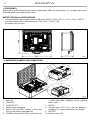
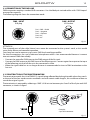
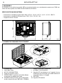
Fig.4
1
3
8
5
4
7
4
3
2
10
9
6
442
175
368
Fig.3
1.4 ECLFRSJBP4
Battery pack kit for EclipseFresnelJ series, composed by ABS case, 4 pcs battery, 1 pc charger, 4 pcs male-
male cable and 4 pcs male-female cables.
BATTERY TECHNICAL SPECIFICATIONS
• Estimated battery life in single colour mode up to: (R) 8 h - (G) 8 h - (B) 7 h - (L) 3 h - (O) 4 h - (RB) 7h
• Estimated battery life in full-mode up to: (TW) 1,25 h - (TU, DY) 1,5h
• Re-charge time: 5h/max
1.5 OPERATING ELEMENTS AND CONNECTIONS
1. ABS case
2. CHARGER
3. CHARGER OUT
4. Button to start charging
5. MAIN FUSE HOLDER: replace a burnt-out
fuse by one of the same type only
6. POWER IN (PowerCON IN): for connection to
a socket (100-240V~/50-60Hz) via the supplied
mains cable.
7. SWITCH
8. Charger status LED: if it is red, the battery is
charging, if it is green, the battery is charged.
9. BATTERY
10. Battery status LED

9
ECLFRJPTW
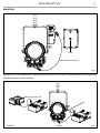
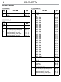
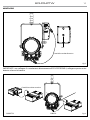
Fig.5
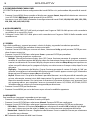
Fig.6
MOUNTING
Holes
DMX cable male-female
DMX cable male-male
CORRECT WRONG
IMPORTANT: do not connect this charger directly to the ECLIPSEFESNELJ, please connect this charger only
with the battery as power charger.

Fig.7
ECLFRJPTW
10
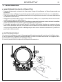
- 2 - INSTALLATION
2.1 MOUNTING
ECLFRJPTW may be set up on a solid and even surface. The unit can also be mounted upside down to a
cross arm. For xing, stable mounting clips are required. The mounting place must be of sucient stability
and be able to support a weight of 10 times of the unit’s weight.
When carrying out any installation, always comply scrupulously with all the regulations (particularly re-
garding safety) currently in force in the country in which the xture’s being used.
• Install the projector at a suitable location by means of the mounting bracket.
• Always additionally secure the projector with the safety rope from falling down. For this purpose, fas-
ten the safety rope at a suitable position so that the maximum fall of the projector will be 20 cm.
• Adjust the projector and use the knob to slightly release or tighten the locking mechanism of the
bracket if is necessary.

11
ECLFRJPTW
- 3 - FUNCTIONS AND SETTINGS
3.1 OPERATION
Connect the supplied main cable to a socket (100-240 VAC-50/60 Hz). Then the unit is ready for operation
and can be operated via a DMX controller or it independently performs its show program in succession.
To switch o, disconnect the mains plug from the socket. For a more convenient operation it is recom-
mended to connect the unit to a socket which can be switched on and o via a light switch.
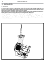
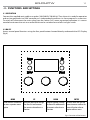
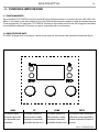
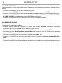
3.2 BASIC
Access control panel functions using the four panel buttons located directly underneath the LED Display
(g.8).
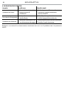
MENU
UP DOWN ENTER
Used to access the menu or
to return a previous menu
option
Navigates downwards through
the menu list and increases
the numeric value when in a
function
Navigates upwards through
the menu list and decreases
the numeric value when in
a function
Used to select and store the
current menu or conrm the
current function value or
option within a menu
Fig.8- Functions of the buttons

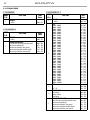
MENU
1 CONNECT
ð
DMX Address
ð
Value (001-512) Default: 001
DMX Mode
ð
1CH
ð
Amber Shift on
Default: 19CH
Color
Temperature
ð
CTO 2800 - 10000K
Hue (025~025)
Default: 2800K
Color Picker
ð
3200K
71
97
100
...
777
Default: 3200K
Customization
ð
Red (000~255)
Orange (000~255)
Green (000~255)
Royal Blue (000~255)
Blue (000~255)
Lime (000~255)
Default: 255
2CH
ð
Amber Shift on
Color
Temperature
ð
CTO 2800 - 10000K
Hue (025~025)
Default: 2800K
Color Picker
ð
3200K
71
97
100
...
777
Default: 3200K
Customization
ð
Red (000~255)
Orange (000~255)
Green (000~255)
Royal Blue (000~255)
Blue (000~255)
Lime (000~255)
Default: 255
5CH1
5CH2
7CH1
7CH2
ð
Color Picker
ð
No Action
3200K
71
97
100
...
777
8CH
9CH
12CH
13CH
16CH
19CH
21CH
2 SETUP
ð
Screen
ð
Back Light
ð
On
10 s
20 s
30 s
Default: 10 s
Flip Display
ð
No-Yes Default: No
Key Lock
ð
No-Yes Default: No
ECLFRJPTW
12
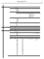
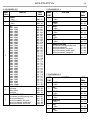
3.3 MENU STRUCTURE

3 ADVANCED
ð
Full On Mode
ð
HB
Studio
Default: Studio
Dimmer Mode
ð
O
Dimmer 1
Dimmer 2
Dimmer 3
Default: O
White Balance
ð
O
Adjust
ð
Red (125~255)
Orange (125~255)
Green (125~255)
Royal Blue (125~255)
Blue (125~255)
Lime (125~255)
Default: O
Led Frequency
ð
600Hz
1200 Hz
2000 Hz
4000 Hz
6000Hz
25kHZ
Default: 1200Hz
Fan Mode
ð
Auto
On
O
Silent
Default : Auto
Factory Reload
ð
No-Yes No-Yes Default: No
4 INFORMATION
ð
Fixture TIme
ð
0-9999
Version
ð
V1.0
UID
ð
15D0021F****
5 STAND ALONE
ð
Master/Slave
ð
Master
Slave
Default : Slave
Eects
ð
Eect1
Eect2
Eect3
Eect4
ð
(1~100) Default: Eect4
Speed=100
CCT
HSI
Color Tempera-
ture
ð
2800K
3000K
3200K
3400K
3600K
3800K
4000K
4200K
4400K
4600K
4800K
5000K
5200K
5400K
5600K
5800K
6000K
6200K
6400K
6600K
6800K
7000K
7200K
7400K
7600K
7800K
8000K
8200K
8400K
8600K
8800K
9000K
9200K
9400K
9600K
9800K
10000K
ð
Dimmer (000~255)
Hue (025~025)
Default : 6000K
Dimmer=255
Hue=0
13
ECLFRJPTW

Fixed Color
ð
R
O
G
RB
B
L
R.0
R.G
R.RB
R.B
R.L
O.G
O.RB
O.B
O.L
G.RB
G.B
G.L
RB.B
RB.L
B.L
R.O.G
R.O.RB
R.O.B
R.O.L
R.G.RB
R.G.B
R.G.L
R.RB.B
R.RB.L
R.B.L
O.G.RB
O.G.B
O.G.L
O.RB.B
O.RB.L
O.B.L
G.RB.B
G.RB.L
G.B.L
RB.B.L
R.O.G.RB
R.O.G.B
R.O.G.L
R.O.RB.B
R.O.RB.L
R.O.B.L
R.G.RB.B
R.G.RB.L
R.G.B.L
R.RB.B.L
O.G.RB.B
O.G.RB.L
O.G.B.L
O.RB.B.L
G.RB.B.L
R.O.G.RB.B
R.O.G.RB.L
R.O.G.B.L
R.O.RB.B.L
R.G.RB.B.L
O.G.RB.B.L
R.O.G.RB.B.L
ð
Dimmer (000~255) Default:
R.O.G.RB.B.L
Dimmer=255
Color Picker
ð
3200K
71
97
100
101
102
103
104
105
106
107
110
111
113
115
116
117
118
119
120
121
122
124
126
128
130
132
134
135
136
137
138
139
141
144
147
151
152
156
157
158
161
164
165
166
170
174
179
180
181
182
195
197
198
200
201
202
203
204
205
206
702
730
777
ð
Dimmer (000~255) Default: 3200K
Manual Color
ð
Red
Orange
Green
Royal Blue
Blue
Lime
ð
(000~255) Default:
RGBW=255
ECLFRJPTW
14

15
ECLFRJPTW
3.4 DMX MODE
• To set the DMX address, press the button MENU so many times until the display shows Connect, then
select throught the buttons UP/DOWN Dmx Address, then press the button ENTER.
• Press UP/DOWN button to select the desired value (001-512). Press and hold to scroll quickly.
• Press ENTER button to store.
• Press the MENU button to go back or to meet the waiting time to exit the setup menu.
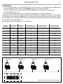
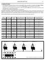
To operate the ECLFRJPTW with a light controller, adjust the DMX start address for the rst a DMX channel.
For example, If the controller is provided with to command the function of the rst DMX channel, adjust
the start address 33 on the ECLFRJPTW. The other functions of the light eect panel are then automatically
assigned to the following addresses.
An example with the start address 33 is shown below:
DMX Address: 48DMX Address: 38DMX Address: 33 DMX Address: 43
Fig.9 - Example 5 DMX channels conguration
DMX512 Controller
Number of
DMX channels
Start address
(example)
DMX Address
occupied
Next possible start
address for unit No. 1
Next possible start
address for unit No. 2
Next possible start
address for unit No. 3
1 33 33 34 35 36
2 33 33-34 35 37 39
5 33 33 - 37 38 43 48
7 33 33 - 39 40 47 54
8 33 33 - 40 41 49 57
9 33 33 - 41 42 51 60
12 33 33 - 44 45 57 69
13 33 33 - 45 46 59 72
16 33 33 - 48 49 65 81
19 33 33 - 51 52 71 90
21 33 33 - 53 54 75 96
. . . . . . . . . . . .

ECLFRJPTW
16
3.5 DMX CONFIGURATION
ECLFRJPTW has several DMX channel congurations that can be accessed from the control panel.
• Press the button MENU so many times until the display shows Connect, then select throught the buttons
UP/DOWN DMX Channel, then press the button ENTER.
• Select the desired DMX conguration (1CH, 2CH, 5CH1, 5CH2, 7CH1, 7CH2, 9CH, 12CH, 13CH, 16CH, 19CH, 21CH)
through the buttons UP/DOWN.
3.6 LINKING
1. Connect the DMX OUT output of the main unit to the DMX IN input of the rst secondary unit using a
5-pin XLR cable.
2. Connect the DMX OUT output of the rst secondary unit to the DMX IN input of the second secondary
unit, etc.
3.7 SCREEN
It is possible to modify the following parameters, related to the display, following the same procedure:
• Press the button MENU to enter the menu mode.
• Press UP/DOWN button to scroll through the menu, select Set Up, then press the ENTER button to access
the next menu.
• Press UP/DOWN button to select Screen and press the ENTER button to proceed.
• Select the proposed option and press the ENTER button to conrm.
- Backlight - Auto O display backlight. This function allows you to switch o automatically the back-
lighting of the display after a certain time which can be set using the directional keys. To have the
display always on select On or set a value between those shown (10s, 20s, 30s) to turn o the display
once the chosen time has elapsed, after exiting the menu.
- Flip Display - Display orientation. This feature allows you to rotate the display by 180 ° to get a better
view of the display when the unit is hanging upside down. Select Yes to activate the function, No to
deactivate it.
- Key lock - With this function, you can lock the keys on the control panel to prevent, for example, tam-
pering with the settings. If this function is activated, the keys are locked automatically. To disable or
temporarily disable or disable the key lock function, press the keys in the following order to regain
access to the menu commands: UP, DOWN, UP, DOWN, ENTER. Select Yes to activate the function or
No to deactivate it.
• Press the ENTER button to conrm the selection.
• Press the MENU button to go back or to meet the waiting time to exit the setup menu.
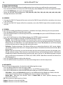
3.8 ADVANCED
You can change the parameters for the device by following these steps:
• Press the button MENU to enter the menu mode.
• Press UP/DOWN button to select the Advanced. Press the ENTER button to conrm.
• Press UP/DOWN button to select the desired option and press the ENTER button to conrm:
- Full On Mode - Select the Full on Mode function to set the HB mode (High Brightness Mode, with the
- maximum value of the colours) or Studio mode with a automatic white balance.
- Dimmer Mode - Adjusting the dimmer. Enter in Dimmer Mode to select specic dimming curve.
Particularly when set:
• O: The increase in light intensity is linear.
• Dimmer 1: dimmer curve with low fade.
• Dimmer 2: dimmer curve with medium fade.

17
ECLFRJPTW
• Dimmer 3: dimmer curve with high fade.
- White Balance - To balance the white on each colour. Select the colour (Red, Orange, Green, Royal Blue,
Blue and Lime) and the value (125 ~ 255) using the UP / DOWN button and press the ENTER button to
conrm.
- LED Frequency - To adjust the frequency of the LEDs. Select the frequency 600 Hz ~ 25 KHz using the UP /
DOWN button and press ENTER to conrm the selection.
- Fan Mode - Fan Speed. Select the fan speed (Auto, On, O, Silent) using the UP / DOWN button.
- Factory Reload - To reset the unit. Select Yes or No and select the UP / DOWN button to conrm.
• Press the MENU button to go back or to meet the waiting time to exit the setup menu.
3.9 INFORMATION
To view all the information on the device, proceed as follows:
• Press the button MENU to enter the menu mode.
• Press UP/DOWN button to select Information, then press the ENTER button to access the next menu.
• Press UP/DOWN button to scroll through the menu, then select one of the following informationa and
press the ENTER button to display it.
- Fixture Time - To view the operating time of the projector.
- Software Version - To view the rmware version will show on the display.
- UID - To view the identication ID for the RDM control.
• Press the MENU button to go back or to meet the waiting time to exit the setup menu.
3.10 MASTER/SLAVE MODE
This mode will allow you to link up the units together without a controller. The rst unit will be set as mas-
ter and other units will work as slave with the same eect.
• Press the button MENU so many times until the display shows Stand Alone, then select throught the
buttons UP/DOWN Master/Slave, then press the button ENTER.
• Press UP/DOWN and select the Master/Slave mode to set the unit as master or slave (Master, Slave).
• Use the ECLFRJPTW DMX connectors and an XLR cable to form a drive chain. In certain conditions and
lengths, it is recommended to terminate as shown on page 18.
3.11 EFFECTS
This xture has a built-in automatic program. To access this, please see the below instructions:
• To enter the Eects mode, press the ENTER button to access the menu.
• Press UP/DOWN button to select Stand Alone, then select Eect. Press ENTER to conrm
• Press UP/DOWN button to select the desired program Eect 1, Eect 2, Eect 3, Eect 4, Eect 5 then press
ENTER to conrm.
• Set the value (1 - 100), then press the ENTER button to conrm.
3.12 STATIC MODE
This xture has the ability to accept custom static color settings. Access these chases via the control panel
on the back of the xture.
• Press the MENU button so many times until the display shows Stand Alone, then press the ENTER button.
• Select Fixed Color through the UP/DOWN buttons, then press the ENTER button.
• Set the colors R , O, G, W, RB, B, L, R.O.G.RB.B.L... R.G.RB.B.L, O.G.RB.B.L, R.O.G.RB.B.L through the UP/DOWN but-
tons, then press the ENTER button.
• Press the MENU button to go back or to meet the waiting time to exit the setup menu.

ECLFRJPTW
18
3.13 MANUAL MODE
To set the customized balance of red, orange, green, royal blue, blue and lime colors, refer to the following
procedure:
• Press the button MENU so many times until the display shows Stand Alone, then select throught the
buttons UP/DOWN Static, then press the button ENTER.
• Select Manual Color Mixer through the buttons UP/DOWN, then press the button ENTER.
• Select the color Red, Orange, Green, Royal Blue, Blue, Lime through the buttons UP/DOWN, then press the
button ENTER.
• Using UP/DOWN button, select the desired color value 000 ~ 255.
• Press ENTER button to continue to the next color Red, Orange, Green, Royal Blue, Blue, Lime.
• Continue until the desired mix is obtained.
• Press the MENU button to go back or to meet the waiting time to exit the setup menu.
La pagina si sta caricando...
La pagina si sta caricando...
La pagina si sta caricando...
La pagina si sta caricando...
La pagina si sta caricando...
La pagina si sta caricando...
La pagina si sta caricando...
La pagina si sta caricando...
La pagina si sta caricando...
La pagina si sta caricando...
La pagina si sta caricando...
La pagina si sta caricando...
La pagina si sta caricando...
La pagina si sta caricando...
La pagina si sta caricando...
La pagina si sta caricando...
La pagina si sta caricando...
La pagina si sta caricando...
La pagina si sta caricando...
La pagina si sta caricando...
La pagina si sta caricando...
La pagina si sta caricando...
La pagina si sta caricando...
La pagina si sta caricando...
La pagina si sta caricando...
La pagina si sta caricando...
La pagina si sta caricando...
La pagina si sta caricando...
La pagina si sta caricando...
La pagina si sta caricando...
La pagina si sta caricando...
La pagina si sta caricando...
La pagina si sta caricando...
La pagina si sta caricando...
La pagina si sta caricando...
La pagina si sta caricando...
La pagina si sta caricando...
La pagina si sta caricando...
La pagina si sta caricando...
La pagina si sta caricando...
La pagina si sta caricando...
La pagina si sta caricando...
La pagina si sta caricando...
La pagina si sta caricando...
-
 1
1
-
 2
2
-
 3
3
-
 4
4
-
 5
5
-
 6
6
-
 7
7
-
 8
8
-
 9
9
-
 10
10
-
 11
11
-
 12
12
-
 13
13
-
 14
14
-
 15
15
-
 16
16
-
 17
17
-
 18
18
-
 19
19
-
 20
20
-
 21
21
-
 22
22
-
 23
23
-
 24
24
-
 25
25
-
 26
26
-
 27
27
-
 28
28
-
 29
29
-
 30
30
-
 31
31
-
 32
32
-
 33
33
-
 34
34
-
 35
35
-
 36
36
-
 37
37
-
 38
38
-
 39
39
-
 40
40
-
 41
41
-
 42
42
-
 43
43
-
 44
44
-
 45
45
-
 46
46
-
 47
47
-
 48
48
-
 49
49
-
 50
50
-
 51
51
-
 52
52
-
 53
53
-
 54
54
-
 55
55
-
 56
56
-
 57
57
-
 58
58
-
 59
59
-
 60
60
-
 61
61
-
 62
62
-
 63
63
-
 64
64


ProLights ECLFRJPTW Manuale utente
- Categoria
- Proiettori
- Tipo
- Manuale utente
in altre lingue
- English: ProLights ECLFRJPTW User manual
Documenti correlati
-
ProLights LED Fresnel pole operated FC and Tunable White Manuale utente
-
-
-
-
-
-
ProLights LED Fresnel Manuale utente
-
-
-
Altri documenti
-
Martin Stagebar 54 Manuale utente
-
SDJ SG JWASH400KIT Manuale utente
-
-
-
CHAUVET DJ Cast Tube Guida di riferimento
-
PIXEL K80 RGB Manuale utente
-
 B K Licht BKL1157 Floor Lamp Manuale utente
-
agape ASPEF90L Assembly Instructions
-
CP Electronics UHS5 Compact Infra Red Commissioning Handset Manuale utente
-
LE LIGHTING EVER 3300008 Manuale utente
