
B5A-4136-00
INSTRUCTION MANUAL
MODE D’EMPLOI
MANUAL DE INSTRUCCIONES
NXR-1800

1
THANK YOU!
We are grateful you purchased this KENWOOD repeater.
PRECAUTIONS
• Do not expose the repeater to rain or moisture in order to prevent
ŰÈ»ÅȻ»¹ÊÈ¿¹É¾Å¹ÁƔ
• Do not open the repeater under any circumstances in order to
·ÌÅ¿ºÊ¾»È¿ÉÁż»Â»¹ÊÈ¿¹É¾Å¹ÁƔ
• Do not expose the repeater to long periods of direct sunlight, nor
place it close to heating appliances.
• Do not place the repeater in excessively dusty and/or humid
areas, nor on unstable surfaces.
Ʒ ÅÄÅÊÆËÊʾ»Æ·ÉÊ¿¹¸·½ËÉ»º¼ÅÈÆ·¹Á¿Ä½Å¼Ê¾¿É»ÇË¿ÆûÄÊ
in a place which can be reached by a small child's hands. It will
¸»¹Åûʾ»¹·ËɻżÉËŮŹ·Ê¿ÅÄ¿¼¿Ê¿ÉÍÅÈĹÅÃÆ»ʻÂÏƔ
ƷÅÄÅÊËÉ»ÅÆÊ¿ÅÄÉÄÅÊÉÆ»¹¿Ű»º¸ÏKENWOOD.
Ʒ ÄÉÊ·ÂÂÅÆÊ¿Åķ·¹¹»ÉÉÅÈ¿»É;»Äʾ»ÆÅÍ»Èżʾ»È»Æ»·Ê»È¿ÉÅŮƔ
Ʒ ¼ÏÅ˺»Ê»¹Ê·Ä·¸ÄÅÈ÷ÂźÅÈÅÈÉÃÅÁ»¹ÅÿĽ¼ÈÅÃʾ»
repeater, disconnect the power from the repeater immediately,
and contact your KENWOOD service center or dealer.
Ʒ ÅÄÅÊÆ·¹»·ÄÏŸÀ»¹ÊÉʾ·Ê÷ϸÂŹÁʾ»Ì»Äʿ·ʿÅÄÉÂÅÊÉ·Ê
the front of the main body or the fan at the rear.
NOTICES TO THE USER
• Government law prohibits the operation of unlicensed radio
transmitters within the territories under government control.
Ʒ »½·ÂÅƻȷʿÅÄ¿ÉÆËĿɾ·¸Â»¸ÏŰÄ»·ÄºƭÅÈ¿ÃÆÈ¿ÉÅÄûÄÊƔ
Ʒ »¼»ÈÉ»ÈÌ¿¹¿Ä½ÊÅÇË·Â¿Ű»ºÊ»¹¾Ä¿¹¿·ÄÉÅÄÂÏƔ
FCC WARNING
¾¿É»ÇË¿ÆûÄʽ»Ä»È·Ê»ÉÅÈËÉ»ÉÈ·º¿Å¼È»Ç˻ĹϻĻȽÏƔ
¾·Ä½»ÉÅÈÃź¿Ű¹·Ê¿ÅÄÉÊÅʾ¿É»ÇË¿ÆûÄÊ÷Ϲ·ËÉ»¾·ÈüËÂ
¿Äʻȼ»È»Ä¹»ËÄ»ÉÉʾ»Ãź¿Ű¹·Ê¿ÅÄÉ·È»»ÎÆÈ»ÉÉÂÏ·ÆÆÈÅÌ»º¸Ï
the party responsible/JVCKENWOOD. The user could lose the
·ËʾÅÈ¿ÊÏÊÅÅƻȷʻʾ¿É»ÇË¿ÆûÄÊ¿¼·ÄËÄ·ËʾÅȿлº¹¾·Ä½»ÅÈ
Ãź¿Ű¹·Ê¿ÅÄ¿É÷º»Ɣ
INFORMATION TO THE DIGITAL DEVICE USER REQUIRED
BY THE FCC
¾¿É»ÇË¿ÆûÄʾ·É¸»»ÄÊ»ÉÊ»º·Äº¼ÅËĺÊŹÅÃÆÂÏͿʾʾ»
limits for a Class B digital device, pursuant to Part 15 of the
FCC Rules. These limits are designed to provide reasonable
protection against harmful interference in a residential
installation.
¾¿É»ÇË¿ÆûÄʽ»Ä»È·Ê»ÉƑËɻɷĺ¹·Ä½»Ä»È·Ê»È·º¿Å
¼È»Ç˻ĹϻĻȽϷĺƑ¿¼ÄÅÊ¿ÄÉʷ»º·ÄºËÉ»º¿Ä·¹¹ÅȺ·Ä¹»
with the instructions, may cause harmful interference to radio
communications. However, there is no guarantee that the
interference will not occur in a particular installation. If this
»ÇË¿ÆûÄʺŻɹ·ËÉ»¾·ÈüË¿Äʻȼ»È»Ä¹»ÊÅÈ·º¿ÅÅÈʻ»̿ɿÅÄ
È»¹»ÆÊ¿ÅÄƑ;¿¹¾¹·Ä¸»º»Ê»ÈÿĻº¸ÏÊËÈĿĽʾ»»ÇË¿ÆûÄÊÅŮ
and on, the user is encouraged to try to correct the interference
by one or more of the following measures:
• Reorient or relocate the receiving antenna.
Ʒ ĹȻ·É»Ê¾»É»Æ·È·Ê¿Åĸ»ÊÍ»»Äʾ»»ÇË¿ÆûÄʷĺȻ¹»¿Ì»ÈƔ
Ʒ ÅÄÄ»¹Êʾ»»ÇË¿ÆûÄÊÊÅ·ÄÅËÊ»ÊÅÄ·¹¿È¹Ë¿Êº¿Ů»È»ÄʼÈÅÃʾ·ÊÊÅ
which the receiver is connected.
• Consult the dealer for technical assistance.
WARNING
• Do not install the repeater in an explosive atmosphere (of
¿ÄŲ·Ã÷¸Â»½·ÉƑºËÉÊÆ·ÈÊ¿¹Â»ÉƑûʷ¿¹ÆÅͺ»ÈÉƑ½È·¿Ä
powders, etc.).
UHF REPEATER
NXR-1800
INSTRUCTION MANUAL
CAUTION
Ʒ ¾¿ÉȻƻ·Ê»È¿É¿Äʻĺ»º¼ÅÈËÉ»·É·Űλº¸·É»ÉÊ·Ê¿ÅÄͿʾ
the antenna located outdoors on the rooftop or on an antenna
tower.
• This repeater is designed for a 13.2 V DC power source. Never
use a 24 V DC or higher source to power the repeater.
• Use only the supplied DC power cable.
• Do not remove the ferrite core connected to the DC power
cable. Removal may cause harmful interference with radio
communications.
• Do not put anything on top of the repeater. Putting something
on top obstructs heat dissipation.
Ʒ ËÈÄÅŮʾ»È»Æ»·Ê»È¿Äʾ»¼ÅÂÂÅͿĽÂŹ·Ê¿ÅÄÉƓ
ÂÅÉ»ÊÅ·Æ»ÈÉÅÄËɿĽ·Æ·¹»Ã·Á»È
• During transmission, do not touch the antenna terminals or the
·ÄÊ»Äķ;ÅÉ»¹Å̻ȿĽ¿É¸ÈÅÁ»ÄƔÅ˹¾¿Ä½Ê¾»Ã÷Ϲ·ËÉ»
¾¿½¾¼È»Ç˻ĹϸËÈÄÉƔ
Ʒ ·Á»ÉËȻʾ·Êʾ»Ê¿Æżʾ»·ÄÊ»ÄÄ·ºÅ»ÉÄÅÊÊÅ˹¾ÏÅËȻϻÉƔ
• Do not touch the metal surface of the repeater during use.
ÅËÄÊʾ»È»Æ»·Ê»ÈÉÅʾ·Êʾ»¹¾·ÉɿɺŻÉÄÅÊ÷Á»¹ÅÄÊ·¹Ê
Ϳʾʾ»ÉÁ¿ÄƔÅÊÊ»ÃƻȷÊËÈ»É÷ϸËÈÄÏÅËÈÉÁ¿ÄƔ
• Continuous listening to loud sounds can cause hearing
¿ÃÆ·¿ÈûÄÊƔɻʾ»Ã¿Ä¿ÃËÃÌÅÂËû»̻ÂÈ»ÇË¿È»ºƔ
• Use only the supplied DC power cable or a KENWOOD
optional DC power cable.
• Do not cut and/or remove the fuse holder on the DC power
cable.
The AMBE+2™ voice coding Technology embodied in this
product is protected by intellectual property rights including
patent rights, copyrights and trade secrets of Digital Voice
Systems, Inc. This voice coding Technology is licensed solely
¼ÅÈËɻͿʾ¿Äʾ¿ÉÅÃÃËÄ¿¹·Ê¿ÅÄÉÇË¿ÆûÄÊƔ¾»ËÉ»Èżʾ¿É
Technology is explicitly prohibited from attempting to extract,
remove, decompile, reverse engineer, or disassemble the
Object Code, or in any other way convert the Object Code into a
human-readable form. U.S. Patent Nos. #7,970,606, #8,359,197,
#8,315,860, and #8,595,002.
Firmware Copyrights
¾»Ê¿Ê»ÊŷĺÅÍÄ»Èɾ¿Æż¹ÅÆÏÈ¿½¾ÊɼÅÈŰÈÃÍ·È»»Ã¸»ºº»º¿Ä
KENWOOD product memories are reserved for JVCKENWOOD
Corporation.
UNPACKING AND CHECKING EQUIPMENT
Note:¾»¼ÅÂÂÅͿĽËÄÆ·¹Á¿Ä½¿Ä¼ÅÈ÷ʿÅĿɼÅÈËÉ»¸ÏÏÅËÈ
KENWOODº»·Â»ÈƑ·Ä·ËʾÅȿлºKENWOOD service center, or
the factory.
·È»¼ËÂÂÏËÄÆ·¹Áʾ»È»Æ»·Ê»ÈƔ»È»¹ÅÃûĺʾ·ÊÏÅË¿º»ÄÊ¿¼Ï
ʾ»¿Ê»ÃÉ¿ÉÊ»º¿Äʾ»¼ÅÂÂÅͿĽʷ¸Â»¸»¼ÅÈ»º¿É¹·Èº¿Ä½Ê¾»Æ·¹Á¿Ä½
material. If any items are missing or have been damaged during
ɾ¿ÆûÄÊƑŰ»·¹Â·¿ÃͿʾʾ»¹·ÈÈ¿»È¿Ãûº¿·Ê»ÂÏƔ
Item Remarks Quantity
DC power cable with fuses (15 A) 4 m (with fuse box) 1
È·¹Á»Ê Short type 1
È·¹Á»Ê Long type 1
Flat head machine screw Åȸȷ¹Á»Ê 4
Reinforcing hardware For connect set 1
Bind head machine screw For reinforcing hardware 8
Handle - 1
Foot - 4
Instruction manual - 1
Note: Use only the supplied screws.

2
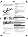
CONTROLS AND FUNCTIONS
Front
Rear
TX RX
CONTROL I/O
Display
Displays the channel information, MENU, or status of the
repeater.
POWER indicator
Lights green while power is supplied within the operating range
ÊÅʾ»ʸʺƔʹÀ·¹Á·ÄºÊ¾»ÆÅÍ»Èżʾ»È»Æ»·Ê»È¿ÉÊËÈÄ»º
on.
ËÈÄÉÅŮ;»Äʾ»ÆÅÍ»ÈÉËÆÆÂÏÌÅÂÊ·½»¿ÉÅËÊÉ¿º»Å¼Ê¾»
ÅƻȷʿĽȷĽ»ÅÈʾ»ÆÅÍ»Èżʾ»È»Æ»·Ê»È¿ÉÊËÈÄ»ºÅŮƔ
POWER switch/selector
The following two methods using the KPG-D7 settings turn the
ÆÅÍ»ÈÅÄÅÈÅŮƓ
• When DC power is supplied to the repeater, the power
is automatically turned on. When power is no longer
ÉËÆÆ¿»ºÊÅʾ»È»Æ»·Ê»ÈƑʾ»ÆÅÍ»ÈͿ¸»ÊËÈÄ»ºÅŮƔ
ƷÈ»ÉɿĽ;¿Â»Ê¾»ÆÅͻȿÉÊËÈÄ»ºÅŮÊËÈÄÉʾ»
ÆÅÍ»ÈÅÄƔ¾»Äʾ»ÆÅͻȿÉÅÄƑÏÅ˹·ÄÊËÈÄ¿ÊÅٸÏ
operating the MENU.
The selector is used to select and set the MENU items.
LAN jack
Connect to the Ethernet. Use a shielded category 5e or higher
standard LAN cable shorter than 3 meters.
USB port (Type-A)
Connect the USB audio accessories (headsets, microphones,
ÉÆ»·Á»ÈÉƑ»Ê¹Ɣƻº¿È»¹ÊÂÏƑÅȹÅÄÄ»¹Êʾ»·Ëº¿Å·¹¹»ÉÉÅÈ¿»ÉÌ¿·
the USB audio adapter.
¾»·Ëº¿Å»ÇË¿ÆûÄÊÊŹÅÄÄ»¹ÊÃËÉÊÉËÆÆÅÈÊ»¿Ê¾»Èʾ»
standard Linux USB audio driver or the standard Windows USB
audio driver.
TX1/ TX2 indicator
During DMR transmission, the TX1 indicator lights red when
communicating with the radio in Timeslot 1, and the TX2
indicator lights red when communicating with the radio in
Timeslot 2.
For anything other than DMR, both TX1 and TX2 are lit during
transmission.
RX1/ RX2 indicator
On the DMR standby channel, the RX1 indicator lights green
while receiving a receivable CC matching signal in Timeslot 1.
The RX2 indicator lights green while receiving a receivable CC
matching signal in Timeslot 2.
For anything other than DMR, both RX1 and RX2 are lit while
receiving a signal with matching signaling and only RX1 is lit
while receiving a signal that does not match signaling.
STATUS indicator
ĺ¿¹·Ê»Éʾ»ÉÊ·ÊËÉżʾ»È»Æ»·Ê»ÈƔ¿ÄÁÉÈ»ºÍ¾¿Â»Ê¾»ÉÊ·ÊËÉ
is abnormal.
Ventilation slots
Fan
DC jack
ÅÄÄ»¹Ê·ʸʺƔʹÆÅÍ»ÈÉËÆÆÂÏÊÅʾ¿ÉÀ·¹ÁƔ
Note: After inserting the connector of the attached DC cable into
ʾ»À·¹ÁƑÊ¿½¾Ê»Äʾ»É¹È»ÍÉÅĸÅʾɿº»Éżʾ»¹ÅÄÄ»¹ÊÅÈ
ŰÈÃÂÏÊÅ·ÌÅ¿ºÊ¾»¼·Â¿ĽÅËÊżʾ»¹ÅÄÄ»¹ÊÅÈƔ
TX OUT jack
Connect a TX antenna or a duplexer to this N receptacle
CONTROL I/O jack
Connect a repeater controller or a remote panel to this
DB-25 interface.
RX IN jack
Connect an RX antenna or a duplexer to this BNC receptacle.
REPEATER OPERATION
Note: Please consult your dealer for programming the repeater.
The RX1/ RX2 indicator lights green while receiving a signal and
the TX1/ TX2 indicator lights red while transmitting.
TRANSCEIVER OPERATION
Note: Connect the audio accessory to the USB port. Consult
your dealer for other methods for transmission and reception by
ËɿĽʾ»·ÆÆ¿¹·Ê¿ÅÄƺ»ÉÊÅÄÉÅ»ƻƑÿ¹ÈÅƾÅÄ»Ƒ·ÄºÉÆ»·Á»È
on a PC connected via a LAN.
Receive
Adjust the volume to your desired level by MENU operation. You
may need to readjust the volume if you are having interference
while receiving a message from your dispatcher or another
ûø»È¿ÄÏÅËÈŲ»»ÊƔ¾»RX1/ RX2 indicator lights green while a
signal is being received.
Transmit
1 ¿ÉÊ»ÄÊÅʾ»¹¾·ÄĻ¸»¼ÅÈ»ÊÈ·ÄÉÿÊʿĽÊÅ÷Á»ÉËÈ»¿Ê¿ÉÄÅÊ
being used.
2 Change the Test PTT Control to ”On” by MENU operation,
ʾ»ÄÉÆ»·Á¿ÄÏÅËÈÄÅÈ÷ÂÉÆ»·Á¿Ä½ÌÅ¿¹»Ɣ¾»TX1/ TX2
indicator lights red while transmitting.
3 ¾»ÄÏÅËŰĿɾÉÆ»·Á¿Ä½Ƒ¹¾·Ä½»Ê¾»Test PTT Control to
ͲŮͲ¸ÏÅƻȷʿÅÄƔ
INSTALLATION
Refer to the diagrams below when mounting the repeater on the
È·¹ÁƔ¼·ÄÅʾ»Èżʾ¿Éº»Ì¿¹»¿ÉÆËȹ¾·É»ºƑÊÍÅȻƻ·Ê»Èɹ·Ä¸»
jointly mounted by using the attached reinforcing hardware.
É»ÅÄ»ÂÅĽƖÊÏÆ»¸È·¹Á»Ê·ÄºÅĻɾÅÈÊƖÊÏÆ»¸È·¹Á»Ê¿¼ÃÅËÄʿĽ
ÅĻȻƻ·Ê»ÈÅÄʾ»È·¹ÁƔÅËÄʿĽ¹·Ä¸»»¿Ê¾»ÈÅÄʾ»Â»¼ÊÅÈ
È¿½¾ÊƔÉ»ÊÍÅɾÅÈÊƖÊÏÆ»¸È·¹Á»ÊÉ¿¼ÃÅËÄʿĽÊÍÅȻƻ·Ê»ÈÉÅÄʾ»
È·¹ÁƔ
Consult your dealer for further detail of installing the repeater and
antenna.
Bracket : Long type
(Used when installing one repeater.)
Bracket : Short type
Reinforcing hardware
(Used when installing two repeaters.)

© 2023
MANDATORY SAFETY INSTRUCTIONS TO INSTALLERS AND
USERS
• Use only manufacturer or dealer supplied antenna.
• Antenna Minimum Safe Distance: Refer to the values in the table
below.
• Antenna Gain: 0 dBd referenced to a dipole.
The Federal Communications Commission has adopted a safety standard
for human exposure to RF (Radio Frequency) energy which is below the
OSHA (Occupational Safety and Health Act) limits.
• Antenna Mounting: The antenna supplied by the manufacturer or
radio dealer must not be mounted at a location such that during
radio transmission, any person or persons can come closer than the
minimum safe distance indicated in the table below.
• To comply with current FCC/ ISED RF Exposure limits, the antenna
must be installed at or exceeding the minimum safe distance shown
above, and in accordance with the requirements of the antenna
manufacturer or supplier.
Ʒ ·É»Ê·Ê¿ÅÄÄÉʷ·ʿÅÄƓ¾»·ÄÊ»ÄķɾÅ˺¸»ŰλºƖÃÅËÄÊ»ºÅÄ
an outdoor permanent structure. RF Exposure compliance must be
addressed at the time of installation.
Antenna substitution: Do not substitute any antenna for the one supplied or
recommended by the manufacturer or radio dealer.
You may be exposing person or persons to excess radio frequency
radiation. You may contact your radio dealer or the manufacturer for further
instructions.
WARNING
Maintain a separation distance from the antenna to person(s) of at least
the distance indicated in the table below.
ÅËƑ·Éʾ»ÇË·Â¿Ű»º»ÄºƖËÉ»Èżʾ¿ÉÈ·º¿Åº»Ì¿¹»ÃËÉʹÅÄÊÈÅÂʾ»»ÎÆÅÉËÈ»
conditions of bystanders to ensure the minimum separation distance (table
below) is maintained between the antenna and nearby persons for satisfying
RF Exposure compliance. The operation of this transmitter must satisfy the
requirements of Occupational/Controlled Exposure Environment, for work-
related use, transmit only when person(s) are at least the minimum distance
from the properly installed, externally mounted antenna.
Antenna Minimum Safe Distance
Frequency Range Rated Power Safe Distance
NXR-1800-E 40 W (duty cycle 50%) 94 cm (3.1 feet)
25 W (duty cycle 100%) 106 cm (3.5 feet)
CONSIGNES DE SÉCURITÉ OBLIGATOIRES DESTINÉES AUX
INSTALLATEURS ET AUX UTILISATEURS
• N’utilisez que des antennes fournies par le fabricant ou le revendeur.
• Distance minimum de sécurité par rapport à l’antenne : Reportez-
vous aux valeurs indiquées dans le tableau ci-dessous.
• Gain d’antenne : 0 dBd par rapport à un dipôle.
La Federal Communications Commission a édicté une norme de sécurité
pour l’exposition humaine à l’énergie des RF (radiofréquences) qui se situe
»Äº»îѺ»Éɻ˿ÂÉŰÎóÉÆ·ÈÂƠƺ¹¹ËÆ·Ê¿Åķ·¼»ÊϷĺ»·Âʾ¹ÊƻƔ
• Installation de l’antenne: l’antenne fournie par le fabricant ou le
revendeur radio ne doit pas être montée dans un endroit tel que
pendant que la transmission par hyperfréquences, des personnes
peuvent se rapprocher de la distance de sécurité minimale indiquée
dans le tableau ci-dessous.
Ʒ Űĺ»È»ÉÆ»¹Ê»È»Éɻ˿ÂÉ·¹ÊË»ÂɺƠ»ÎÆÅÉ¿Ê¿ÅÄ·ËÎŰÎóÉÆ·È·
FCC/ ISED, l’antenne doit être installée à une distance supérieure
ou égale à la distance minimum de sécurité indiquée ci-dessus et en
accord avec les exigences du fabricant ou du fournisseur de l’antenne.
• Installation de la station de base : l’antenne doit être installée sur
une structure permanente extérieure. Les seuils d’exposition à la RF
doivent être respectés lors de l’installation.
Remplacement de l’antenne : ne remplacez pas l’antenne par celle fournie
ou recommandée par le fabricant ou le revendeur de la radio.
Vous risquez d’exposer une ou plusieurs personnes à un niveau de
radiofréquence excessif. Vous pouvez vous adresser à votre revendeur ou
au fabricant pour plus d’informations.
AVERTISSEMENT
Maintenir une distance de séparation de l’antenne aux personnes d’au
minimum la distance indiquée dans le tableau ci-dessous.
ÅËɺ»Ì»ÐƑ»ÄÌÅÊÈ»Ç˷¿ÊóºƠËʿ¿ɷʻËÈŰÄ·ÂÇ˷¿Ű󺻹»Ê·ÆÆ·È»¿ÂÈ·º¿ÅƑ
¹ÅÄÊÈĥ»È»ɹÅĺ¿Ê¿ÅÄɺƠ»ÎÆÅÉ¿Ê¿Åĺ»ÉÆ·ÉÉ·ÄÊÉ·Űĺ»ÌÅËÉ·ÉÉËÈ»ÈÇË»
la distance minimum de séparation (tableau ci-dessous) est maintenue
»ÄÊÈ»ÂƠ·ÄÊ»ÄÄ»»Ê»ÉÆ»ÈÉÅÄĻɷ»ÄÊÅËÈ·Űĺ»É·Ê¿É¼·¿È»·ËÎÄÅÈûÉ
d’exposition à la RF. Le fonctionnement de cet émetteur doit satisfaire aux
exigences d’un environnement à exposition contrôlée/professionnel pour
l’utilisation liée au travail, n’émettre que lorsqu’une ou plusieurs personnes
se trouvent à une distance au moins égale à la distance minimum par
rapport à l’antenne correctement installée en extérieur.
Distance minimum de sécurité par rapport à l'antenne
Gamme de
fréquences Puissance nominale Distance de sécurité
NXR-1800-E 40 W (cycle de service 50%) 94 cm (3,1 pieds)
25 W (cycle de service 100%) 106 cm (3,5 pieds)
SUPPLIER'S DECLARATION OF CONFORMITY
47 CFR § 2.1077 Compliance Information
Trade name: KENWOOD
Model(s): NXR-1800-E
Responsible party: JVCKENWOOD USA Corporation 1440 Corporate Drive, Irving, TX 75038 USA
Telephone number: 972-819-0700
-
 1
1
-
 2
2
-
 3
3
-
 4
4


in altre lingue
- English: Kenwood NXR-1800 User manual
- français: Kenwood NXR-1800 Manuel utilisateur
- português: Kenwood NXR-1800 Manual do usuário