
ISTRUZIONI D’USO E DI INSTALLAZIONE
INSTALLATION AND USER’S MANUAL
INSTRUCTIONS D’UTILISATION ET D’INSTALLATION
INSTALLATIONS-UND GEBRAUCHSANLEITUNG
INSTRUCCIONES DE USO Y DE INSTALACION
INSTALLATIEVOORSCHRIFTEN
ATTUATORE PER CANCELLI SCORREVOLI A CREMAGLIERA
ACTUATOR FOR RACK SLIDING GATES
ACTIONNEUR POUR PORTAILS COULISSANTS Á CRÉMAILLÈRE
TRIEB FÜR SCHIEBETORE MIT ZAHNSTANGE
ACCIONADOR PARA CANCELAS CORREDERAS DE CREMALLERA
ACTUATOR VOOR SCHUIFHEKKEN MET TANDHEUGEL
Attenzione! Leggere attentamente le “Avvertenze” all’interno! Caution! Read “Warnings” inside carefully! Attention! Veuillez lire attentivement les Avertissements qui se trouvent à l’intérieur! Achtung! Bitte lesen Sie
aufmerksam die „Hinweise“ im Inneren! ¡Atención¡ Leer atentamente las “Advertencias”en el interior! Let op! Lees de “Waarschuwingen” aan de binnenkant zorgvuldig!
D811727 00100_10 19-11-14
8
027908 372246
SP 3500

INSTALLAZIONE VELOCE-QUICK INSTALLATION-INSTALLATION RAPIDE
SCHNELLINSTALLATION-INSTALACIÓN RÁPIDA - SNELLE INSTALLATIE
3x0,75mm
2
2x0,75mm
2
3x0,75mm
2
2x1.5mm
2
RG58
*
380-400V 3~5x2.5 mm
2
/ 220-230V 3~4x2.5 mm
2
5x0,75mm
2
Montaggio accessori trasmissione, Mounting drive accessories,
Montage accessoires transmission, Montage Antriebszubehör,
Montaje de accesorios transmisión, Montage accessoires overbrenging.
FISSAGGIO STAFFE FINECORSA / FASTENING LIMIT SWITCH BRACKETS /
FIXATION ÉTRIERS FINS DE COURSE / BEFESTIGUNG BÜGEL ENDSCHALTER
/
FIJACIÓN ABRAZADERAS FINAL DE CARRERA / BEVESTIGING STANGEN AANSLAG
D1
D
1
3
C
B
A
PREDISPOSIZIONE TUBI, TUBE ARRANGEMENT,
PRÉDISPOSITION DES TUYAUX,
VORBEREITUNG DER LEITUNGEN,
DISPOSICIÓN DE TUBOS,VOORBEREIDING LEIDINGEN.
*
5-6 cm
5-6 cm
E
Lato uscita pignone
Pinion exit side
Côté sortie de pignon
Seite des zahnrades
Lato salita piñón
70
Min. 10
43
Piano superiore
Top level
Oberseite
Dessus supérieur
Supercie superior
117 137
2
non in dotazione
not provided
pas fournis
nicht mitgeliefert
no incluido en el kit
niet meegeleverd
1
2
3
0-20 mm
V1
V1 D1
60
M12
12
D1
+
APERTURA/OPENING/OUVERTURE/ÖFFNUNG/APERTURA/OPENINGA
CLICK
V2 R1
+
CHIUSURA/CLOSING/FERMETURE/SCHLIESSUNG/CIERRE/SLUITING
CLICK
V2 R1
+
Y
Y
>172
V2
R1
10 mm
6,4 mm
6 mm
2 - SP 3500
D811727 00100_10

ITALIANO ENGLISH
FRANÇAIS
DEUTSCH
ESPAÑOL
NEDERLANDS
Collegamento morsettiera,
Terminal board wiring,
Connexion plaque à bornes,
Anschluss Klemmleiste,
Conexión tablero de bornes, Aansluiting aansluitkast.
F
G
H
ON
1
2
CLONIX 1-2
JP 2
JP1 SIRIO TEL 230
JP1 SIRIO TEL 400
JP7
Fig.O-P
10 19
11 12 13 14 15 16 17 18
1
2 3 4
41 40 39 38 37
8 9
20 21 22 23 24 25
24V
3W
ANT.
2°CHR
SCA
LOOP1
24V AUX
~
OV AUX/ V SAFE
-
V SAFE
+
LOOP2
1
2 3 4 8 9
220-230V
40W
230V
40W
R
X
S T
220-230V
~
50/60Hz
RN S T
380-400V
~
50/60Hz
JP4
26 36
27 28 29 30 31 32 33 34 35
NO
NC
NC
NC
NC
NC
NO
NO
NO
X
COM
START
STOP
PED
OPEN
CLOSE
PHOT
BAR
SWO
SWC
S
NC SAFETY
1
2
1
2
3
4
5
11
12
12
11
26
29
TX1 RX1
1
2
3
4
5
6
11
12
26
35
11
Vsafe +
LOOP 1
LOOP 2
24V AUX ~
0V AUX ~
JP 2
1
0
19
11 12 13 14 15 16 17 18
JP4
26
36
27 28 29 30 31 32 33 34 35
DIP9= ON, DIP10= ON
2AF
2AT
0.2AT
*(non in dotazione/not provided/pas fournis/nicht mitgeliefert/no incluido en el kit/niet meegeleverd)
*1(fornito/provided/fourni/mitgeliefert/incluido en el kit/geleverd)
DL1
220-230V
~
220-230V ~ 380-400V SAFETY
S
COM
PHOT
BAR
PG13.5 *1
Motore, motor
Moteur, Motor
PG9 *1
Finecorsa, Limit switches
Fins de course, Endschalter
Final de carrera, Aanslag
PG16 *1
Alimentazione,
Power supply
Alimentation
Stromversorgung
Alimentación
Voeding
PG9 *
PHOT TX
PG9 *
PHOT RX
PG9 *
BAR
PG9 *
RG58
PG9-SP *
SAFETY
PG9 *
Lampeggiante
Flashing light
Clignotant
Blinkleuchte
Indicador parpadeante
Knipperlicht
PG9 *
Selettore
Selector
Sélecteur
Wahlschalter
Selector
Schakelaar
non in dotazione
not provided
pas fournis
nicht mitgeliefert
no incluido en el kit
niet meegeleverd
SP 3500 - 3
D811727 00100_10

J
I
440
241
52.5
30
545
186
254
117
Øp114 - Z19 - M6
x1
55
450
251
da 0 a 20
M
N
L
K
NO
OK
OK
START
ON
1
2
ON
1
2
ON
1
2
ON
1
2
ON
1
2
ON
1
2
380-400V 3~
50/60Hz
50/60Hz
2
TEST
98 97 96 95
220-230V 3~
3
TEST
98 97 96 95
N1
Swc
Open Close
SwoKO
Swc
Close Open
SwoOK
1
N R S T
2 3 4
Invertire morsetti 3-4 / Swap over terminals 3-4
Inverser les bornes 3-4 / Klemmen 3-4 vertauschen
Invertir los bornes 3-4 / Klemmen 3-4 omkeren
4 - SP 3500
D811727 00100_10

O
PHOTOCELLS
FOTOCÉLULAS
PHOTOCEL
FOTOCELLEN
COSTE
LEISTEN
SAFETY EDGES
CANTOS
LINTEAUX
RANDEN
1
2
1
2
3
4
5
13
12
11
12
26
29
TX1 RX1
14
2 PHOT1 PHOT
3 PHOT
1 BAR 2 BAR
3 BAR 4 BAR
4 PHOT
1
2
3
4
5
6
11
12
26
35
14
13
1
2
1
2
3
4
5
13
12
11
12
26
29
TX1 RX1
1
2
1
2
3
4
5
13
12
11
12
14
26
TX2 RX2
1
2
1
2
3
4
5
13
12
11
12
26
29
TX1 RX1
1
2
1
2
3
4
5
13
12
11
12
24
23
25
TX2 RX2
1
2
1
2
3
4
5
13
12
11
12
14
26
TX3 RX3
24
25
21
20
22
23
1
2
1
2
3
4
5
13
12
11
12
26
29
TX1
RX1
1
2
1
2
3
4
5
13
12
11
12
TX2
RX2
1
2
1
2
3
4
5
13
12
11
12
TX3
RX3
1
2
1
2
3
4
5
13
12
11
12
14
26
TX4
RX4
1
2
3
4
5
6
11
12
26
35
13
1
2
3
4
5
6
11
12
14
26
13
1
2
3
4
5
6
11
12
26
35
13
1
2
3
4
5
6
11
12
24
23
13
1
2
3
4
5
6
11
12
14
25
26
13
1
2
3
4
5
6
11
12
26
35
13
1
2
3
4
5
6
11
12
13
23
24
1
2
3
4
5
6
11
12
22
14
26
13
1
2
3
4
5
6
13
20
21
25
12
11
COM
BAR
PHOT
JP7
LOOP 1
LOOP 2
Vsafe +
24V AUX ~
0V AUX ~
JP 2
1
0
19
11 12 13 14 15 16 17 18
20 21 22 23 24 25
JP4
26
36
27 28 29 30 31 32 33 34 35
FOTOCELLULE
FOTOZELLEN
DIP 10 = OFF DIP 9 = OFF
SP 3500 - 5
D811727 00100_10

P
1
2
1
2
3
4
5
13
12
11
12
26
29
TX1 RX1
1
2
3
4
5
6
11
12
15
35
13
1
2
3
4
5
6
11
12
15
35
13
1
2
3
4
5
6
11
12
35
13
26
1
2
3
4
5
6
11
12
26
13
1
2
3
4
5
6
11
12
35
13
26
1
2
3
4
5
6
11
12
23
13
27
1
2
3
4
5
6
11
12
25
26
13
1
2
3
4
5
6
11
12
26
35
13
1
2
3
4
5
6
11
12
23
13
24
1
2
3
4
5
6
11
12
25
26
13
1
2
3
4
5
6
11
12
35
13
26
1
2
3
4
5
6
11
12
23
13
24
1
2
3
4
5
6
11
12
25
20
13
21
1
2
3
4
5
6
11
12
22
26
13
1
2
3
4
5
6
11
12
15
35
13
1
2
3
4
5
6
11
12
15
35
13
1
2
1
2
3
4
5
13
12
11
12
26
29
TX1 RX1
1
2
1
2
3
4
5
13
12
11
12
29
TX1 RX1
15
1
2
1
2
3
4
5
13
12
11
12
29
TX1 RX1
15
1
2
1
2
3
4
5
13
12
11
12
26
TX1 RX1
22
1
2
1
2
3
4
5
13
12
11
12
21
20
TX1 RX1
15
1
2
1
2
3
4
5
13
12
11
12
29
TX1 RX1
15
1
2
1
2
3
4
5
13
12
11
12
26
TX2 RX2
1
2
1
2
3
4
5
13
12
11
12
26
29
TX1 RX1
1
2
1
2
3
4
5
13
12
11
12
24
23
25
TX2 RX2
1
2
1
2
3
4
5
13
12
11
12
26
TX3 RX3
1
2
1
2
3
4
5
13
12
11
12
26
29
TX1 RX1
1
2
1
2
3
4
5
13
12
11
12
24
23
25
TX2 RX2
1
2
1
2
3
4
5
13
12
11
12
26
TX3 RX3
24
25
21
20
22
23
1
2
1
2
3
4
5
13
12
11
12
26
29
TX1
RX1
1
2
1
2
3
4
5
13
12
11
12
TX2
RX2
1
2
1
2
3
4
5
13
12
11
12
TX3
RX3
1
2
1
2
3
4
5
13
12
11
12
26
TX4
RX4
1
2
3
4
5
6
11
12
35
13
22
1
2
3
4
5
6
11
12
21
20
13
15
DIP9 = OFF, DIP 10 = OFF
DIP9 = OFF, DIP 10 = OFF
BAR
PHOT
JP7
LOOP 1
LOOP 2
Vsafe +
24V AUX
~
0V AUX ~
JP 2
1
0
19
11 12 13 14 15 16 17 18
20 21 22 23 24 25
JP4
26
36
27 28 29 30 31 32 33 34 35
COM
1 PHOT + 1 BAR
2 PHOT + 1 BAR
1
2
3
4
5
6
11
12
22
35
13
1
2
3
4
5
6
11
12
15
20
13
21
1
2
1
2
3
4
5
13
12
11
12
26
29
TX1 RX1
1
2
1
2
3
4
5
13
12
11
12
26
TX2 RX2
2 PHOT + 2 BAR
3 PHOT + 1 BAR 3 BAR + 1 PHOT
3 PHOT + 2 BAR
3 BAR + 2 PHOT
4 PHOT + 1 BAR
4 BAR + 1 PHOT
2 BAR + 1 PHOT
6 - SP 3500
D811727 00100_10

SIRIOTEL
400
52
53
N R S T
50
51
48
49
45
46
47
42
43
44
40 39 38 37
K0
NC
K3 K2 A1
A2
A1
A2
A1 K1
26 27 28 29 30 31
20 21 22 23 24 25
32 33 34 35 36
10 11 12 13 14 15 16 17 18 19
400V
*
5*
1*
4*
2*3*
~ ~+
M
3~
R
N
S T
8 9
380-400V
~
*
7 x 1,5 mm
2
Q
SP 3500 - 7
D811727 00100_10

220-230V
R
SIRIOTEL
230
52
53
N R S T
50
51
48
49
45
46
47
42
43
44
40 39 38 37 41
K0
NC
K3 K2 A1
A2
A1
A2
A1 K1
26 27 28 29 30 31
20 21 22 23 24 25
32 33 34 35 36
10 11 12 13 14 15 16 17 18 19
*
5*
1*
4*
2*3*
~ ~+
M
3~
R
S T
8 9
220-230V
~
*
7 x 1,5 mm
2
8 - SP 3500
D811727 00100_10

INSTALLER WARNINGS
Anything that is not explicitly provided for in the installation ma-
nual is not allowed. The operator’s proper operation can only be
guaranteed if the information given is complied with. The Firm shall
not be answerable for damage caused by failure to comply with the
instructions featured herein.
While we will not alter the product’s essential features, the Firm reserves
the right, at any time, to make those changes deemed opportune to
improve the product from a technical, design or commercial point of
view, and will not be required to update this publication accordingly.
WARNING! Important safety instructions. Carefully read and comply with
all the warnings and instructions that come with the product as incorrect
installation can cause injury to people and animals and damage to property.
The warnings and instructions give important information regarding safety,
installation, use and maintenance. Keep hold of instructions so that you can
attach them to the technical le and keep them handy for future reference.
GENERAL SAFETY
This product has been designed and built solely for the purpose indicated herein.
Uses other than those indicated herein might cause damage to the product and
create a hazard.
- The units making up the machine and its installation must meet the requirements
of the following European Directives, where applicable: 2004/108/EC, 2006/95/
EC, 2006/42/EC, 89/106/EC, 99/05/EC and later amendments. For all countries
outside the EEC, it is advisable to comply with the standards mentioned, in ad-
dition to any national standards in force, to achieve a good level of safety.
- The Manufacturer of this product (hereinafter referred to as the “Firm”) disclaims
all responsibility resulting from improper use or any use other than that for
which the product has been designed, as indicated herein, as well as for failure
to apply Good Practice in the construction of entry systems (doors, gates, etc.)
and for deformation that could occur during use.
- Installation must be carried out by qualied personnel (professional installer,
according to EN 12635), in compliance with Good Practice and current code.
- Before installing the product, make all structural changes required to produce
safety gaps and to provide protection from or isolate all crushing, shearing and
dragging hazard areas and danger zones in general in accordance with the
provisions of standards EN 12604 and 12453 or any local installation standards.
Check that the existing structure meets the necessary strength and stability
requirements.
- Before commencing installation, check the product for damage.
- The Firm is not responsible for failure to apply Good Practice in the construction
and maintenance of the doors, gates, etc. to be motorized, or for deformation
that might occur during use.
- Make sure the stated temperature range is compatible with the site in which the
automated system is due to be installed.
- Do not install this product in an explosive atmosphere: the presence of ammable
fumes or gas constitutes a serious safety hazard.
- Disconnect the electricity supply before performing any work on the system.
Also disconnect buer batteries, if any are connected.
- Before connecting the power supply, make sure the product’s ratings match the
mains ratings and that a suitable residual current circuit breaker and overcurrent
protection device have been installed upline from the electrical system. Have
the automated system’s mains power supply tted with a switch or omnipolar
thermal-magnetic circuit breaker with a contact separation that provide full
disconnection under overvoltage category III conditions.
- Make sure that upline from the mains power supply there is a residual current
circuit breaker that trips at no more than 0.03A as well as any other equipment
required by code.
- Make sure the earth system has been installed correctly: earth all the metal parts
belonging to the entry system (doors, gates, etc.) and all parts of the system
featuring an earth terminal.
- Installation must be carried out using safety devices and controls that meet
standards EN 12978 and EN 12453.
- Impact forces can be reduced by using deformable edges.
- In the event impact forces exceed the values laid down by the relevant standards,
apply electro-sensitive or pressure-sensitive devices.
- Apply all safety devices (photocells, safety edges, etc.) required to keep the
area free of impact, crushing, dragging and shearing hazards. Bear in mind the
standards and directives in force, Good Practice criteria, intended use, the instal-
lation environment, the operating logic of the system and forces generated by
the automated system.
- Apply all signs required by current code to identify hazardous areas (residual
risks). All installations must be visibly identied in compliance with the provisions
of standard EN 13241-1.
- Once installation is complete, apply a nameplate featuring the door/gate’s data.
- This product cannot be installed on leaves incorporating doors (unless the motor
can be activated only when the door is closed).
- If the automated system is installed at a height of less than 2.5 m or is accessible,
the electrical and mechanical parts must be suitably protected.
- Install any xed controls in a position where they will not cause a hazard, away
from moving parts. More specically, hold-to-run controls must be positioned
within direct sight of the part being controlled and, unless they are key operated,
must be installed at a height of at least 1.5 m and in a place where they cannot
be reached by the public.
- Apply at least one warning light (ashing light) in a visible position, and also
attach a Warning sign to the structure.
- Attach a label near the operating device, in a permanent fashion, with informa-
tion on how to operate the automated system’s manual release.
- Make sure that, during operation, mechanical risks are avoided or relevant
protective measures taken and, more specically, that nothing can be banged,
crushed, caught or cut between the part being operated and surrounding parts.
- Once installation is complete, make sure the motor automation settings are
correct and that the safety and release systems are working properly.
- Only use original spare parts for any maintenance or repair work. The Firm dis-
claims all responsibility for the correct operation and safety of the automated
system if parts from other manufacturers are used.
- Do not make any modications to the automated system’s components unless
explicitly authorized by the Firm.
- Instruct the system’s user on what residual risks may be encountered, on the
control systems that have been applied and on how to open the system manu-
ally in an emergency. give the user guide to the end user.
- Dispose of packaging materials (plastic, cardboard, polystyrene, etc.) in accord-
ance with the provisions of the laws in force. Keep nylon bags and polystyrene
out of reach of children.
WIRING
WARNING! For connection to the mains power supply, use: a multicore cable with
a cross-sectional area of at least 5x1.5mm
2
or 4x1.5mm
2
when dealing with three-
phase power supplies or 3x1.5mm
2
for single-phase supplies (by way of example,
type H05 VV-F cable can be used with a cross-sectional area of 4x1.5mm
2
). To con-
nect auxiliary equipment, use wires with a cross-sectional area of at least 0.5 mm
2
.
- Only use pushbuttons with a capacity of 10A-250V or more.
- Wires must be secured with additional fastening near the terminals (for example,
using cable clamps) in order to keep live parts well separated from safety extra
low voltage parts.
- During installation, the power cable must be stripped to allow the earth wire
to be connected to the relevant terminal, while leaving the live wires as short
as possible. The earth wire must be the last to be pulled taut in the event the
cable’s fastening device comes loose.
WARNING! safety extra low voltage wires must be kept physically separate from
low voltage wires.
Only qualied personnel (professional installer) should be allowed to access
live parts.
CHECKING THE AUTOMATED SYSTEM AND MAINTENANCE
Before the automated system is nally put into operation, and during maintenance
work, perform the following checks meticulously:
- Make sure all components are fastened securely.
- Check starting and stopping operations in the case of manual control.
- Check the logic for normal or personalized operation.
- For sliding gates only: check that the rack and pinion mesh correctly with 2 mm
of play along the full length of the rack; keep the track the gate slides on clean
and free of debris at all times.
- For sliding gates and doors only: make sure the gate’s running track is straight
and horizontal and that the wheels are strong enough to take the weight of the
gate.
- For cantilever sliding gates only: make sure there is no dipping or swinging
during operation.
- For swing gates only: make sure the leaves’ axis of rotation is perfectly vertical.
-For barriers only: before opening the door, the spring must be decompressed
(vertical boom).
- Check that all safety devices (photocells, safety edges, etc.) are working properly
and that the anti-crush safety device is set correctly, making sure that the force
of impact measured at the points provided for by standard EN 12445 is lower
than the value laid down by standard EN 12453.
- Impact forces can be reduced by using deformable edges.
- Make sure that the emergency operation works, where this feature is provided.
- Check opening and closing operations with the control devices applied.
- Check that electrical connections and cabling are intact, making extra sure that
insulating sheaths and cable glands are undamaged.
- While performing maintenance, clean the photocells’ optics.
- When the automated system is out of service for any length of time, activate the
emergency release (see “EMERGENCY OPERATION” section) so that the operated
part is made idle, thus allowing the gate to be opened and closed manually.
-
If the power cord is damaged, it must be replaced by the manufacturer or their
technical assistance department or other such qualied person to avoid any risk .
- If “D” type devices are installed (as dened by EN12453), connect in unveried
mode, foresee mandatory maintenance at least every six months
- The maintenance described above must be repeated at least once yearly or at
shorter intervals where site or installation conditions make this necessary.
WARNING!
Remember that the drive is designed to make the gate/door easier to use and
will not solve problems as a result of defective or poorly performed installation
or lack of maintenance
SCRAPPING
Materials must be disposed of in accordance with the regulations in
force. Do not throw away your discarded equipment or used batteries
with household waste. You are responsible for taking all your waste
electrical and electronic equipment to a suitable recycling centre.
DISMANTLING
If the automated system is being dismantled in order to be reassembled at another
site, you are required to:
- Cut o the power and disconnect the whole electrical system.
- Remove the actuator from the base it is mounted on.
- Remove all the installation’s components.
- See to the replacement of any components that cannot be removed or happen
to be damaged.
THE DECLARATION OF CONFORMITY CAN BE VIEWED ON THIS WEBSITE:
WWW.BFT.IT IN THE PRODUCT SECTION.
AVVERTENZE PER L’INSTALLATORE D811766_12
12 - SP 3500
D811727 00100_10

INSTALLATION MANUAL
ENGLISH
1) GENERAL INFORMATION
The SP3500 operator consists of a strong gearmotor.
The self-braking motor and irreversible gearbox allow the gate to stop quickly,
avoiding uncontrolled sliding of the gate due to the eect of inertia.
The gearmotor is coupled to the gate by means of a rack. The control panel is
built in and comprises: start relay, three-phase motor protector, control unit.
The operating logic provides for various congurations so that use of the automa-
ted device can be tailored to the user’s needs (e.g.: automatic closing, controlled
closing, photocells active during closing etc.). To edit settings, call in qualied
personnel (installer).
The irreversible gearmotor keeps the gate locked closed, meaning there is no
need to use solenoid locks.
A manual release system allows the gate to be opened manually in the event of
a mains power outage or malfunctioning.
In deadman mode, check the gate stopping distance: if it exceeds 50mm, cover
the closing edge with a rubber prole whose deformation is greater than the
stopping distance and results in less than 150N of static force being generated
on a test body measuring 80mm in diameter.
2) TECHNICAL SPECIFICATIONS
MOTOR
Power supply*
SIRIOTEL 400: 3-phase + N 380-400V
~
50/60Hz
SIRIOTEL 230: 3-phase + 220-230V
~
50/60Hz
Power demand 0.55 kW
Max. current demand 2A (380-400V); 3A (220-230V)
Protection motor protector wired in panel
Insulation class F
Reduction ratio 1/50
Pinion module m=6mm z=19 teeth
Maximum leaf weight 35000N (≈3500kg)
Leaf speed 10.5 m/min
Impact reaction stop (with safety edge)
Gearbox lubrication oil
Manual operation key-operated mechanical release
Control unit SIRIO TEL with interface
Environmental conditions from -15°C to +50°C
Protection rating IP 54
Dimensions Fig. J
Operator weight 54 kg.
Max. travel 30 m
Out speed 28 rpm
Use 100% up to 2200 kg. / 60% over 2200 kg.
CONTROL UNIT
Power supply 3-phase + N 380-400V~: 3-phase 220-230V~ 50/60 Hz
Low voltage/mains insulation
> 2MOhm 500V
LV/mains dielectric rigidity 3750V~ 1’
Accessories power supply 24V~/0.5A
Gate open light 24V/3W
(*) Special supply voltages to order.
(*) 3-phase 220-230V power supply available.
3) TUBE ARRANGEMENT Fig.A
Install the electrical system referring to the standards in force for electrical systems CEI
64-8, IEC 364, harmonization document HD 384 and other national standards.
4) PREPARATION FOR MOTOR MOUNTING FIG. B-K
• Makeaholeinthegroundtoaccommodatetheconcretepad,withanchors
embedded in the base plate for fastening the gearbox assembly, keeping to the
distances featured in FIG.B.
5) MOUNTING THE MOTOR FIG.C
6) MOUNTING DRIVE ACCESSORIES FIG.D-D1
7) RACK CENTRING WITH RESPECT TO PINION FIG.L
DANGER - Welding must be performed by a competent person issued
with the necessary personal protective equipment as prescribed by
the safety rules in force.
8) FASTENING LIMIT SWITCH BRACKETS FIG.E
9) STOPS FIG.M
DANGER - The gate must be tted with mechanical stops to halt its
travel both when opening and closing, thus preventing the gate from
coming o the top guide. Said stops must be fastened rmly to the ground,
a few centimetres beyond the electric stop point.
10) MANUAL RELEASE (See USER GUIDE -FIG.2-).
Warning: do not JERK the gate open and closed, instead push it GENTLY to
the end of its travel.
11) MOTOR PROTECTOR FIG. N
Make sure it is set for the motor’s rated current demand (380-400V/2A) (220-
230V/3A).
12) CHECKING DIRECTION FIG.N1
Release the motor and move the gate half way along its travel. Relock the motor
then turn the power o and back on. Give the start command. If the gate does
not move in the opening direction, swap the phase wires over. WARNING: also
check that limit switches SWO-SWC are working properly.
13) TERMINAL BOARD WIRING FIG. F-G
Once suitable electric cables have been run through the raceways and the automa-
ted device’s various components have been fastened at the predetermined points,
connect them as directed and illustrated in the diagrams contained in the relevant
instruction manuals.
Connect the live, neutral and earth wire (compulsory) Fig. Q-R.
TERMINAL
DEFINITION DESCRIPTION
1
2
3
4
N
R
S
T
Three-phase power supply 380-400V~, 50-60Hz
N NEUTRAL
R LINE 1
S LINE 2
T LINE 3
2
3
4
R
S
T
Three-phase power supply 220-230V~, 50-60Hz
R LINE 1
S LINE 2
T LINE 3
8-9 BLINK 230V Flashing light 230V output max. 40W.
10-11 SCA
Free contact (N.O.).
Gate Open Light output SCA 24V~ max. 3W.
11 24V AUX ~
Accessories power supply:
24V~ operation with mains power on.
12 0V AUX ~
12 Vsafe -
Safety device power supply output (photocell transmit-
ter and safety edge transmitter).
N.B.: output active only during operating cycle.
24V~ Vsafe operation with mains power on.13
Vsafe +
14
LOOP 1
Safety device test input LOOP 1 (see g.G)
15
LOOP 2
Safety device test input LOOP 2 (see g.
G
)
16-17 2°CH.R
Free contact (N.O.).
2nd radio channel output. 24V~ max. 3W.
18
19
ANT
SHIELD
Antenna (18 signal - 19 braiding).
Use an antenna tuned to 433MHz. Use RG58 coax cable
to connect the Antenna and Receiver. Metal bodies
close to the antenna can interfere with radio reception.
If the transmitter's range is limited, move the antenna to
a more suitable position.
20-21-22
INPUTS OF
TESTED
DEVICES
Tested safety device connection (see g.O-P)
23-24-25
INPUTS OF
TESTED
DEVICES
Tested safety device connection (see g.O-P)
26-27 START
START command input (N.O.).
Operation according to 2-4-step logic.
26-28 STOP
STOP input (N.C.)
The command stops movement.
If not used, leave jumper inserted.
26-29 PHOT
PHOTOCELLinput (N.C.) Operation according to photocell
during opening logic. If not used, leave jumper inserted.
26-30 SWO
Opening limit switch SWO (N.C.). If not used, leave jumper
inserted.
26-31 SWC
Closing limit switch SWC (N.C.). If not used, leave jumper
inserted.
26-32 PED
PEDESTRIAN command input (N.O.)The command causes
the automated device to open to the pedestrian opening
position.
26-33 OPEN
OPEN command input (N.O.).The command causes the
leaves to open. If the contact stays closed, the leaves
stay open until the contact is opened. When the contact
is open, the automated device closes following the TCA
time, where activated.
26-34 CLOSE
CLOSEcommand input (N.O.).
The command causes the leaves to close.
26-35 BAR
Safety edge input BAR (N.C.).
The command reverses movement for 2 sec.
If not used, leave jumper inserted.
36 Not used Not used
40-53 See wiring g. Q-R
INSTALLER WARNINGS
Anything that is not explicitly provided for in the installation ma-
nual is not allowed. The operator’s proper operation can only be
guaranteed if the information given is complied with. The Firm shall
not be answerable for damage caused by failure to comply with the
instructions featured herein.
While we will not alter the product’s essential features, the Firm reserves
the right, at any time, to make those changes deemed opportune to
improve the product from a technical, design or commercial point of
view, and will not be required to update this publication accordingly.
WARNING! Important safety instructions. Carefully read and comply with
all the warnings and instructions that come with the product as incorrect
installation can cause injury to people and animals and damage to property.
The warnings and instructions give important information regarding safety,
installation, use and maintenance. Keep hold of instructions so that you can
attach them to the technical le and keep them handy for future reference.
GENERAL SAFETY
This product has been designed and built solely for the purpose indicated herein.
Uses other than those indicated herein might cause damage to the product and
create a hazard.
- The units making up the machine and its installation must meet the requirements
of the following European Directives, where applicable: 2004/108/EC, 2006/95/
EC, 2006/42/EC, 89/106/EC, 99/05/EC and later amendments. For all countries
outside the EEC, it is advisable to comply with the standards mentioned, in ad-
dition to any national standards in force, to achieve a good level of safety.
- The Manufacturer of this product (hereinafter referred to as the “Firm”) disclaims
all responsibility resulting from improper use or any use other than that for
which the product has been designed, as indicated herein, as well as for failure
to apply Good Practice in the construction of entry systems (doors, gates, etc.)
and for deformation that could occur during use.
- Installation must be carried out by qualied personnel (professional installer,
according to EN 12635), in compliance with Good Practice and current code.
- Before installing the product, make all structural changes required to produce
safety gaps and to provide protection from or isolate all crushing, shearing and
dragging hazard areas and danger zones in general in accordance with the
provisions of standards EN 12604 and 12453 or any local installation standards.
Check that the existing structure meets the necessary strength and stability
requirements.
- Before commencing installation, check the product for damage.
- The Firm is not responsible for failure to apply Good Practice in the construction
and maintenance of the doors, gates, etc. to be motorized, or for deformation
that might occur during use.
- Make sure the stated temperature range is compatible with the site in which the
automated system is due to be installed.
- Do not install this product in an explosive atmosphere: the presence of ammable
fumes or gas constitutes a serious safety hazard.
- Disconnect the electricity supply before performing any work on the system.
Also disconnect buer batteries, if any are connected.
- Before connecting the power supply, make sure the product’s ratings match the
mains ratings and that a suitable residual current circuit breaker and overcurrent
protection device have been installed upline from the electrical system. Have
the automated system’s mains power supply tted with a switch or omnipolar
thermal-magnetic circuit breaker with a contact separation that provide full
disconnection under overvoltage category III conditions.
- Make sure that upline from the mains power supply there is a residual current
circuit breaker that trips at no more than 0.03A as well as any other equipment
required by code.
- Make sure the earth system has been installed correctly: earth all the metal parts
belonging to the entry system (doors, gates, etc.) and all parts of the system
featuring an earth terminal.
- Installation must be carried out using safety devices and controls that meet
standards EN 12978 and EN 12453.
- Impact forces can be reduced by using deformable edges.
- In the event impact forces exceed the values laid down by the relevant standards,
apply electro-sensitive or pressure-sensitive devices.
- Apply all safety devices (photocells, safety edges, etc.) required to keep the
area free of impact, crushing, dragging and shearing hazards. Bear in mind the
standards and directives in force, Good Practice criteria, intended use, the instal-
lation environment, the operating logic of the system and forces generated by
the automated system.
- Apply all signs required by current code to identify hazardous areas (residual
risks). All installations must be visibly identied in compliance with the provisions
of standard EN 13241-1.
- Once installation is complete, apply a nameplate featuring the door/gate’s data.
- This product cannot be installed on leaves incorporating doors (unless the motor
can be activated only when the door is closed).
- If the automated system is installed at a height of less than 2.5 m or is accessible,
the electrical and mechanical parts must be suitably protected.
- Install any xed controls in a position where they will not cause a hazard, away
from moving parts. More specically, hold-to-run controls must be positioned
within direct sight of the part being controlled and, unless they are key operated,
must be installed at a height of at least 1.5 m and in a place where they cannot
be reached by the public.
- Apply at least one warning light (ashing light) in a visible position, and also
attach a Warning sign to the structure.
- Attach a label near the operating device, in a permanent fashion, with informa-
tion on how to operate the automated system’s manual release.
- Make sure that, during operation, mechanical risks are avoided or relevant
protective measures taken and, more specically, that nothing can be banged,
crushed, caught or cut between the part being operated and surrounding parts.
- Once installation is complete, make sure the motor automation settings are
correct and that the safety and release systems are working properly.
- Only use original spare parts for any maintenance or repair work. The Firm dis-
claims all responsibility for the correct operation and safety of the automated
system if parts from other manufacturers are used.
- Do not make any modications to the automated system’s components unless
explicitly authorized by the Firm.
- Instruct the system’s user on what residual risks may be encountered, on the
control systems that have been applied and on how to open the system manu-
ally in an emergency. give the user guide to the end user.
- Dispose of packaging materials (plastic, cardboard, polystyrene, etc.) in accord-
ance with the provisions of the laws in force. Keep nylon bags and polystyrene
out of reach of children.
WIRING
WARNING! For connection to the mains power supply, use: a multicore cable with
a cross-sectional area of at least 5x1.5mm
2
or 4x1.5mm
2
when dealing with three-
phase power supplies or 3x1.5mm
2
for single-phase supplies (by way of example,
type H05 VV-F cable can be used with a cross-sectional area of 4x1.5mm
2
). To con-
nect auxiliary equipment, use wires with a cross-sectional area of at least 0.5 mm
2
.
- Only use pushbuttons with a capacity of 10A-250V or more.
- Wires must be secured with additional fastening near the terminals (for example,
using cable clamps) in order to keep live parts well separated from safety extra
low voltage parts.
- During installation, the power cable must be stripped to allow the earth wire
to be connected to the relevant terminal, while leaving the live wires as short
as possible. The earth wire must be the last to be pulled taut in the event the
cable’s fastening device comes loose.
WARNING! safety extra low voltage wires must be kept physically separate from
low voltage wires.
Only qualied personnel (professional installer) should be allowed to access
live parts.
CHECKING THE AUTOMATED SYSTEM AND MAINTENANCE
Before the automated system is nally put into operation, and during maintenance
work, perform the following checks meticulously:
- Make sure all components are fastened securely.
- Check starting and stopping operations in the case of manual control.
- Check the logic for normal or personalized operation.
- For sliding gates only: check that the rack and pinion mesh correctly with 2 mm
of play along the full length of the rack; keep the track the gate slides on clean
and free of debris at all times.
- For sliding gates and doors only: make sure the gate’s running track is straight
and horizontal and that the wheels are strong enough to take the weight of the
gate.
- For cantilever sliding gates only: make sure there is no dipping or swinging
during operation.
- For swing gates only: make sure the leaves’ axis of rotation is perfectly vertical.
-For barriers only: before opening the door, the spring must be decompressed
(vertical boom).
- Check that all safety devices (photocells, safety edges, etc.) are working properly
and that the anti-crush safety device is set correctly, making sure that the force
of impact measured at the points provided for by standard EN 12445 is lower
than the value laid down by standard EN 12453.
- Impact forces can be reduced by using deformable edges.
- Make sure that the emergency operation works, where this feature is provided.
- Check opening and closing operations with the control devices applied.
- Check that electrical connections and cabling are intact, making extra sure that
insulating sheaths and cable glands are undamaged.
- While performing maintenance, clean the photocells’ optics.
- When the automated system is out of service for any length of time, activate the
emergency release (see “EMERGENCY OPERATION” section) so that the operated
part is made idle, thus allowing the gate to be opened and closed manually.
-
If the power cord is damaged, it must be replaced by the manufacturer or their
technical assistance department or other such qualied person to avoid any risk .
- If “D” type devices are installed (as dened by EN12453), connect in unveried
mode, foresee mandatory maintenance at least every six months
- The maintenance described above must be repeated at least once yearly or at
shorter intervals where site or installation conditions make this necessary.
WARNING!
Remember that the drive is designed to make the gate/door easier to use and
will not solve problems as a result of defective or poorly performed installation
or lack of maintenance
SCRAPPING
Materials must be disposed of in accordance with the regulations in
force. Do not throw away your discarded equipment or used batteries
with household waste. You are responsible for taking all your waste
electrical and electronic equipment to a suitable recycling centre.
DISMANTLING
If the automated system is being dismantled in order to be reassembled at another
site, you are required to:
- Cut o the power and disconnect the whole electrical system.
- Remove the actuator from the base it is mounted on.
- Remove all the installation’s components.
- See to the replacement of any components that cannot be removed or happen
to be damaged.
THE DECLARATION OF CONFORMITY CAN BE VIEWED ON THIS WEBSITE:
WWW.BFT.IT IN THE PRODUCT SECTION.
AVVERTENZE PER L’INSTALLATORE D811766_12
SP 3500 - 13
D811727 00100_10

INSTALLATION MANUAL
14) TRIMMER
Trimmer Min. Max. Denition Description
TCA
1 120 Automatic closing time [s]
Waiting time before automatic closing.
TW 2 210 Motor work time [s] Time motor(s) is/are powered for
TW.PED 5 60 Pedestrian work time [s] Partial opening time for motor 2 following activation of PED pedestrian command.
15) DIP SWITCH
DIP
Default
Denition
Cross out
setting used
Description
1-2
OFF
Photocells during
opening
ON
In the event beam is broken, photocell operation is disabled during opening. During closing, movement is reversed immediately.
Logic enabled on Phot input.
OFF
In the event beam is broken, photocells are active during both opening and closing. When beam is broken during closing,
movement is reversed only once the photocell is cleared.Logic active on Phot input.
3 OFF
Block pulses during
opening
ON The start pulse has no eect during opening.
OFF The start pulse has eect during opening.
4
ON
Automatic Closing
Time
ON Switches automatic closing on
OFF Switches automatic closing o
5 OFF 2-step logic
ON Switches to 2-step logic; with each pulse, start reverses movement.
OFF Switches to 4-step logic.
6 OFF Pre-alarm
ON The ashing light comes on approx. 3 seconds before the motor(s) start.
OFF The ashing light comes on at the same time as the motor(s) start.
7 OFF Deadman
ON
Aects signals connected to terminals 26-33 and 26-34.
Deadman mode: operation continues as long as the OPEN and CLOSE control keys are held down.
OFF
Pulse operation, according to 2, 3 or 4-step logic.
8 OFF
Reduced work time
scale
ON TW work time falls within the range 1 to 90 seconds (pedestrian work time TW.PED range from 1 to 20 seconds)
OFF TW work time falls within the range 3 to 210 seconds (pedestrian work time TW.PED range from 5 to 60 seconds).
9 ON Photocell test
ON
Switches photocell testing o.
Inhibits the photocell testing function, enabling connection of devices not equipped with supplementary test contacts.
OFF Switches photocell testing on (Fig. O-P)
10 ON Safety edge testing
ON
Switches safety edge testing o.
Inhibits the safety edge testing function, enabling connection of devices not equipped with supplementary test contacts.
OFF Switches safety edge testing on (Fig. O-P)
16) DIAGNOSTICS and WARNINGS
Diagnostics
code
Description Notes
DL1
Steadily lit:
- Mains power on - Board powered - Fuse F1 intact
DL2 On when motor is activated during closing.
DL3 On when motor is activated during opening.
DL4
On:
-START input activated
-Radio receiver 1st channel activated
DL5
O:
-STOP input activated
DL6
O:
-PHOT photocell input activated
DL7
O:
-SWC closing limit switch input activated
DL8
O:
SWO opening limit switch input activated
DL9
On:
-PED pedestrian input activated
DL10
On:
-OPEN pedestrian input activated
DL11
On:
-CLOSE pedestrian input activated
DL12
O:
-BAR safety edge input activated
DL13
On:
-With safety loop closed
17) SAFETY DEVICES
Note: only use receiving safety devices with free changeover contact.
17.1) TESTED DEVICES (Fig.O-P)
17.2) NON-TESTED DEVICES (Fig.H) one pair of photocells and one safety
edge.
18) WIRING DIAGRAM FOR BUILT-IN CONTROL UNIT Fig.Q-R
ATTENTION ! Instructions de sécurité importantes. Veuillez lire et suivre
attentivement tous les avertissements et toutes les instructions fournis
avec le produit sachant qu’une installation incorrecte peut provoquer des
préjudices aux personnes, aux animaux ou aux biens. Les avertissements
fournissent des indications importantes concernant la sécurité, l’installation,
l’utilisation et l’entretien. Veuillez conserver les instructions pour les joindre
au dossier technique et pour d’ultérieures consultations.
SECURITE GÉNÉRALE
Ce produit a été conçu et réalisé exclusivement pour l’usage indiqué dans cette
documentation. Tout usage autre que celui indiqué risque d’endommager le
produit et d’être une source de danger.
- Les éléments qui composent l’appareil et le montage doivent être conformes
aux Directives Européennes suivantes : 2004/108/CE, 2006/95/CE, 2006/42/CE,
89/106/CE, 99/05/CE et leurs modications successives. Pour les pays n’appar-
tenant pas à la CEE, il est conseillé de respecter également les normes citées,
outre les règlements nationaux en vigueur, an de garantir un bon niveau de
sécurité.
- Le Fabricant de ce produit (par la suite « le Fabricant ») décline toute respon-
sabilité dérivant d’un usage incorrect ou diérent de celui prévu et indiqué
dans la présente documentation, de l’inobservation de la bonne technique de
construction des huisseries (portes, portails, etc.) et des déformations pouvant
apparaître à l’usage.
-Le montage doit être accompli par du personnel qualié (monteur profession-
nel, conformément à EN12635), dans le respect de la bonne technique et des
normes en vigueur.
- Avant d’installer le produit apportez toutes les modications structurelles
nécessaires pour réaliser les butées de sécurité et la protection ou ségréga-
tion de toutes les zones présentant un risque d’écrasement, de cisaillement,
d’entraînement ou autre, conformément aux normes EN 12604 et 12453 ou les
éventuelles normes locales sur l’installation. - Vériez si la structure existante
est susamment robuste et stable.
- Avant de commencer le montage, vérier l’intégrité du produit.
- Le fabricant décline toute responsabilité en cas d’inobservation de la bonne
technique de construction et d’entretien des huisseries motorisées, ainsi que
de déformations survenant en cours d’utilisation.
- Vérier si l’intervalle de température déclaré est compatible avec le lieu destiné
à l’installation de l’automatisation.
- Ne pas installer ce produit dans une atmosphère explosive: la présence de gaz
ou de fumées inammables constitue un grave danger pour la sécurité.
- Mettre hors tensions l’installation avant d’accomplir une quelconque interven-
tion. Déconnecter également les batteries tampon éventuellement présentes.
- Avant de mettre hors tension, vérier si les données de la plaque d’identica-
tion correspondent à celles du secteur et s’il y a en amont de l’installation élec-
trique un disjoncteur et une protection adéquats contre la surintensité. Pré-
voyez sur le réseau d’alimentation de l’automatisation un interrupteur ou un
magnétothermique omnipolaire permettant de procéder à une déconnexion
totale dans les conditions de la catégorie de surtension III.
- Vérier s’il y a en amont du réseau d’alimentation un disjoncteur dont le seuil
ne dépasse pas 0,03A et les prescriptions des règlements en vigueur.
- Vérier si l’installation de mise à la terre est réalisée correctement. Connecter
toutes les parties métalliques de la fermeture (portes, portails, etc..) et tous les
composants de l’installation munis de borne de terre.
- L’installation doit être équipée de dispositifs de sécurité et de commandes
conformes aux normes EN 12978 et EN12453.
- Les forces de choc peuvent être réduites à l’aide de rebords déformables.
- Si les forces de choc dépassent les valeurs prévues par les normes, appliquer
des dispositifs électrosensibles ou sensibles à la pression.
- Appliquer tous les dispositifs de sécurité (photocellules, linteaux sensibles,
etc..) nécessaires pour protéger la zone contre les risques de choc, d’écrase-
ment, d’entraînement ou de cisaillement. Tenir compte des règlements et des
directives en vigueur, des critères de bonne technique, de l’utilisation, de l’envi-
ronnement de l’installation, de la logique de fonctionnement du système et
des forces développées par l’automatisation.
- Appliquer les signaux prévus par les règlements en vigueur pour indiquer les
zones de danger (risques résiduels). Toutes les installations doivent être identi-
ées de façon visible conformément aux prescriptions de EN13241-1.
- Au terme de l’installation, appliquez une plaque d’identication de la porte/du
portail.
- Ce produit ne peut pas être installé sur des vantaux munis de portes (à moins
que le moteur ne puisse être actionné qu’avec la prote fermée).
bSi l’automatisation est installée à une hauteur inférieure à 2,5 m ou si elle est
accessible, il est indispensable de garantir un degré de protection adapté aux
parties électriques et mécaniques.
- Installer toutes commandes xes en hauteur de façon à ce qu’elles ne repré-
sentent pas une source de danger et qu’elles soient éloignées des parties
mobiles. En particulier les commandes à homme présent doivent être visibles
directement de la partie guidée et- à moins qu’il n’y ait une clé, se trouver à 1,5 m
minimum de hauteur de façon à être inaccessibles au public.
- Appliquer au moins un dispositif de signalement lumineux (clignotant) visible,
xer également un panneau Attention sur la structure.
- Fixer, à proximité de l’organe de manœuvre et de façon permanente, une éti-
quette sur le fonctionnement du déverrouillage manuel de l’automatisation.
- S’assurer que soient évités pendant la manœuvre les risques mécaniques et, en
particulier, l’écrasement, l’entraînement et le cisaillement par la partie guidée
et les parties voisines.
-
Une fois l’installation accomplie, s’assurer que le réglage du moteur est correct et
que les systèmes de protection et de déverrouillage fonctionnement correctement.
- Utiliser exclusivement des pièces détachées originales pour les opérations
d’entretien ou les réparations. Le Fabricant décline toute responsabilité quant
à la sécurité et au bon fonctionnement de l’automatisation en cas d’utilisation
de composants d’autres Fabricants.
- Ne modier d’aucune façon les composants de l’automatisation sans l’autorisa-
tion expresse du Fabricant.
- Informer l’utilisateur de l’installation sur les risques résiduels éventuels, sur les
systèmes de commande appliqués et sur la façon de procéder à l’ouverture
manuelle en cas d’urgence: remettre le manuel d’utilisation à l’utilisateur nal.
- Eliminer les matériaux d’emballage (plastique, carton, polystyrène, etc.) confor-
mément aux normes en vigueur. Ne pas laisser les sachets en plastique et la
mousse de polystyrène à la portée des enfants.
Tout ce qui n’est pas expressément prévu dans le manuel de montage
est interdit. Le bon fonctionnement de l’appareil n’est garanti que si
les données indiquées sont respectées. Le Fabricant ne répond pas des
dommages provoqués par l’inobservation des indications données
dans ce manuel.
En laissant inaltérées les caractéristiques essentielles de l’appareil,
l’entreprise se réserve le droit d’apporter à tout moment les modi-
cations qu’elle jugera opportunes pour améliorer le produit du point
de vue technique, commercial et de sa construction, sans s’engager à
mettre à jour la présente publication.
AVERTISSEMENTS POUR LE MONTEUR
CONNEXIONS
ATTENTION ! Pour le branchement sur le secteur, utiliser un câble multipolaire
ayant une section minimum de 5x1,5mm
2
ou de 4x1,5mm
2
pour alimentation tri-
phasée ou de 3x1,5mm
2
pour alimentation monophasée (par exemple, le câble
peut être du type H05 VV-F avec une section de 4x1,5mm
2
). Pour le branchement
des auxiliaires, utiliser des conducteurs de 0,5 mm
2
de section minimum.
- Utiliser exclusivement des touches ayant une portée supérieure ou égale à
10A-250V.
- Immobiliser les conducteurs à l’aide d’une xation supplémentaire à proximité
des bornes (par exemple, à l’aide d’un collier) an de séparer nettement les
parties sous tension des parties sous très faible tension de sécurité.
-
Pendant l’installation, dénuder le câble d’alimentation an de pouvoir bran-
cher le conducteur de terre sur la borne appropriée en laissant cependant les
conducteurs actifs aussi courts que possibles. Le conducteur de terre doit être
le dernier à se tendre en cas de desserrement du dispositif de xation du câble.
ATTENTION ! Les conducteurs à très faible tension de sécurité doivent être phy-
siquement séparés des conducteurs à basse tension.
Seul le personnel qualié (monteur professionnel) doit pouvoir accéder aux par-
ties sous tension.
VÉRIFICATION DE L’AUTOMATISATION ET ENTRETIEN
Vérier scrupuleusement ce qui suit avant de rendre l’automatisation dénitive-
ment opérationnelle et pendant les interventions d’entretien:
- Vérier si tous les composants sont solidement xés.
- Vérier le fonctionnement du démarrage et de l’arrêt en cas de commande
manuelle.
- Vérier la logique de fonctionnement normale ou personnalisée.
- Uniquement sur les portails coulissants: vérier si l’engrenage crémaillère - pi-
gnon est correct, avec un jeu de 2 mm le long de toute la crémaillère; le rail de
glissement doit être toujours propre et dépourvu de débris.
- Uniquement sur les portails coulissants: vérier si le rail du portail est droit et
horizontal et si les roues sont en mesure de supporter le poids du portail.
- Uniquement sur les portails coulissants suspendus en porte-à-faux: vérier
l’absence d’abaissement ou d’oscillation pendant la manœuvre.
- Uniquement sur les portails à battant : vérier si l’axe de rotation des vantaux
est parfaitement vertical.
-Uniquement pour les barrières: avant d’ouvrir le portillon le ressort doit être
déchargé (barre verticale).
-
Contrôler le bon fonctionnement de tous les dispositifs de sécurité (photocel-
lules, linteaux sensibles etc..) et le bon réglage du dispositif de sécurité anti-écra-
sement, en vériant si la valeur de la force de choc mesurée aux endroits prévus
par la norme EN12445 est inférieure à celle indiquée par la norme EN12453.
- Les forces de choc peuvent être réduites à l’aide de rebords déformables.
- Vérier le bon fonctionnement de la manœuvre d’urgence s’il y en a une.
- Vérier le bon fonctionnement à l’ouverture et à la fermeture avec les disposi-
tifs de commande appliqués.
- Vérier l’intégrité des connexions électriques et des câblages, en particulier
l’état des gaines isolantes et des presse-câbles.
- Pendant les opérations d’entretien, nettoyer les lentilles des photocellules.
- Pendant la période de mise hors service de l’automatisation, activer le déver-
rouillage d’urgence (cf. paragraphe MANŒUVRE D’URGENCE) de façon à libérer
la partie guidée et à pouvoir accomplir l’ouverture et la fermeture manuelles
due portail.
- Si le câble d’alimentation est endommagé, il doit être remplacé par le constructeur
ou par son service après-vente ou par une personne qualiée, an d’éviter tout
risque.
- Si on installe des dispositifs du type D (tels que dénis par la EN12453), branchés
en mode non vérié, prescrire un entretien obligatoire au moins tous les six mois.
- L’entretien décrit plus haut doit être répété au moins une fois par an ou plus
fréquemment si les caractéristiques du site ou de l’installation le demandent.
ATTENTION !
Ne pas oublier que la motorisation facilite l’utilisation du portail/de la porte
mais qu’elle ne résout pas les problèmes imputables à des défauts ou à des
erreurs de montage ou encore à l’absence d’entretien.
DÉMOLITION
Eliminez les matériaux en respectant les normes en vigueur. Ne jetez
ni les vieux appareils, ni les piles, ni les batteries usées avec les ordures
domestiques. Vous devez coner tous vos déchets d’appareils électri-
ques ou électroniques à un centre de collecte diérenciée, préposé à
leur recyclage.
DÉMANTÈLEMENT
Si l’automatisation est démontée pour ensuite être remontée sur un autre site, il faut:
- Couper l’alimentation et débrancher toute l’installation électrique.
- Retirer l’actionneur de la base de xation.
- Démonter tous les composants de l’installation.
- Remplacer les composants ne pouvant pas être retirés ou endommagés.
LA DÉCLARATION DE CONFORMITÉ PEUT ÊTRE CONSULTÉE SUR LE SITE:
WWW.BFT.IT DANS LA SECTION PRODUITS.
AVVERTENZE PER L’INSTALLATORE D811766_12
14 - SP 3500
D811727 00100_10

Fig.2
MANUALE D’USO: MANOVRA MANUALE/ USER’S MANUAL: MANOVRA MANUALE/ MANUEL D’UTILISATION: MANOVRA MANUALE/
BEDIENUNGSANLEITUNG: MANOVRA MANUALE/ MANUEL DE USO: MANOVRA MANUALE/ MANUAL PARA DE USO: MANOVRA MANUALE
E
C
A
B
D
CLOSE
OPEN
SP 3500 - 27
D811727 00100_10

28 - SP 3500
D811727 00100_10
AVVERTENZE PER L’UTILIZZATORE ( I )
ATTENZIONE! Importanti istruzioni di sicurezza.
Leggere e seguire attentamente le Avvertenze
e le Istruzioni che accompagnano il prodotto
poiché un uso improprio può causare danni a
persone, animali o cose. Conservare le istruzioni
per consultazioni future e trasmetterle ad even-
tuali subentranti nell’uso dell’impianto.
Questo prodotto dovrà essere destinato solo
all’uso per il quale è stato espressamente insta-
llato. Ogni altro uso è da considerarsi improprio
e quindi pericoloso. Il costruttore non può essere
considerato responsabile per eventuali danni
causati da usi impropri, erronei e irragionevoli.
SICUREZZA GENERALE
Nel ringraziarVi per la preferenza accordata a questo
prodotto, la Ditta è certa che da esso otterrete le
prestazioni necessarie al Vostro uso.
Questo prodotto risponde alle norme riconosciute
della tecnica e della disposizioni relative alla si-
curezza se correttamente installato da personale
qualicato ed esperto (installatore professionale).
L’automazione, se installata ed utilizzata corretta-
mente, soddisfa gli standard di sicurezza nell’uso.
Tuttavia è opportuno osservare alcune regole di
comportamento per evitare inconvenienti acci-
dentali:
- Tenere bambini, persone e cose fuori dal raggio
d’azione dell’automazione, in particolare durante
il movimento.
- Non permettere a bambini di giocare o sostare nel
raggio di azione dell’automazione.
- Questa automazione non è destinata all’uso da
parte di bambini o da parte di persone con ridotte
capacità mentali, siche e sensoriali, o persone che
mancano di conoscenze adeguate a meno che
esse non abbiano potuto beneciare, attraverso
l’intermediazione di una persona responsabile della
loro sicurezza, di una sorveglianza o di istruzioni
riguardanti l’uso dell’apparecchio.
- I bambini devono essere sorvegliati per sincerarsi
che non giochino con l’apparecchio. Non permet-
tere ai bambini di giocare con i controlli ssi. Tenere
i telecomandi lontani dai bambini.
-
Evitare di operare in prossimità delle cerniere o organi
meccanici in movimento.
-
Non contrastare il movimento dell’anta e non ten-
tare di aprire manualmente la porta se non è stato
sbloccato l’attuatore con l’apposita manopola di
sblocco.
-
Non entrare nel raggio di azione della porta o can-
cello motorizzati durante il loro movimento.
- Non lasciare radiocomandi o altri dispositivi di
comando alla portata dei bambini onde evitare
azionamenti involontari.
- L’attivazione dello sblocco manuale potrebbe
causare movimenti incontrollati della porta se in
presenza di guasti meccanici o di condizioni di
squilibrio.
- In caso di apritapparelle: sorvegliare la tapparella
in movimento e tenere lontano le persone nché
non è completamente chiusa. Porre cura quando si
aziona lo sblocco se presente, poiché una tapparella
aperta potrebbe cadere rapidamente in presenza
di usura o rotture.
-
La rottura o l’usura di organi meccanici della porta
(parte guidata), quali ad esempio cavi, molle, sup-
porti, cardini, guide.. potrebbe generare pericoli. Far
controllare periodicamente l’impianto da personale
qualicato ed esperto (installatore professionale)
secondo quanto indicato dall’installatore o dal
costruttore della porta.
- Per ogni operazione di pulizia esterna, togliere
l’alimentazione di rete.
- Tenere pulite le ottiche delle fotocellule ed i dispo-
sitivi di segnalazione luminosa. Controllare che rami
ed arbusti non disturbino i dispositivi di sicurezza.
- Non utilizzare l’automatismo se necessita di
interventi di riparazione. In caso di guasto o di
malfunzionamento dell’automazione, togliere
l’alimentazione di rete sull’automazione, astenersi
da qualsiasi tentativo di riparazione o intervento
diretto e rivolgersi solo a personale qualicato ed
esperto (installatore professionale) per la neces-
saria riparazione o manutenzione. Per consentire
l’accesso, attivare lo sblocco di emergenza (se
presente).
-
Per qualsiasi intervento diretto sull’automazione o
sull’impianto non previsto dal presente manuale,
avvalersi di personale qualicato ed esperto (insta-
llatore professionale).
- Con frequenza almeno annuale far verifi-
care l’integrità e il corretto funzionamento
dell’automazione da personale qualificato ed
esperto (installatore professionale), in particolare
di tutti i dispositivi di sicurezza.
- Gli interventi d’installazione, manutenzione e
riparazione devono essere documentati e la
relativa documentazione tenuta a disposizione
dell’utilizzatore.
- Il mancato rispetto di quanto sopra può creare
situazioni di pericolo.
DEMOLIZIONE
L’eliminazione dei materiali va fatta rispettan-
do le norme vigenti. Non gettate il vostro
apparecchio scartato, le pile o le batterie usate
nei riuti domestici. Avete la responsabilità di
restituire tutti i vostri riuti da apparecchia-
ture elettriche o elettroniche lasciandoli in
un punto di raccolta dedicato al loro riciclo.
Tutto quello che non è espressamente previs-
to nel manuale d’uso, non è permesso. ll buon
funzionamento dell’operatore è garantito solo
se vengono rispettate le prescrizioni riportate
in questo manuale. La Ditta non risponde dei
danni causati dall’inosservanza delle indicazioni
riportate in questo manuale.
Lasciando inalterate le caratteristiche essenziali
del prodotto, la Ditta si riserva di apportare in
qualunque momento le modiche che essa ritie-
ne convenienti per migliorare tecnicamente, cos-
truttivamente e commercialmente il prodotto,
senza impegnarsi ad aggiornare la presente
pubblicazione.
USER WARNINGS (GB)
WARNING! Important safety instructions. Ca-
refully read and comply with the Warnings and
Instructions that come with the product as impro-
per use can cause injury to people and animals
and damage to property. Keep the instructions
for future reference and hand them on to any
new users.
This product is meant to be used only for the
purpose for which it was explicitly installed.
Any other use constitutes improper use and,
consequently, is hazardous. The manufacturer
AVVERTENZE PER L’UTILIZZATORE D811767_05

SP 3500 - 29
D811727 00100_10
cannot be held liable for any damage as a result
of improper, incorrect or unreasonable use.
GENERAL SAFETY
Thank you for choosing this product. The Firm is
condent that its performance will meet your ope-
rating needs.
This product meets recognized technical standards
and complies with safety provisions when installed
correctly by qualied, expert personnel (professional
installer).
If installed and used correctly, the automated system
will meet operating safety standards. Nonetheless,
it is advisable to observe certain rules of behaviour
so that accidental problems can be avoided:
- Keep adults, children and property out of range of
the automated system, especially while it is moving.
- Do not allow children to play or stand within range
of the automated system.
- This automated system is not meant for use by
children or by people with impaired mental, phy-
sical or sensory capacities, or people who do not
have suitable knowledge, unless a person who is
responsible for their safety provides them with
necessary supervision or instructions on how to
use the device.
- Children must be supervised to ensure they do not
play with the device. Do not allow children to play
with the xed controls. Keep remote controls out
of reach of children.
-
Do not work near hinges or moving mechanical parts.
- Do not hinder the leaf’s movement and do not
attempt to open the door manually unless the ac-
tuator has been released with the relevant release
knob.
- Keep out of range of the motorized door or gate
while they are moving.
- Keep remote controls or other control devices out
of reach of children in order to avoid the automated
system being operated inadvertently.
- The manual release’s activation could result in un-
controlled door movements if there are mechanical
faults or loss of balance.
- When using roller shutter openers: keep an eye
on the roller shutter while it is moving and keep
people away until it has closed completely. Exercise
care when activating the release, if such a device
is tted, as an open shutter could drop quickly in
the event of wear or breakage.
- The breakage or wear of any mechanical parts of
the door (operated part), such as cables, springs,
supports, hinges, guides…, may generate a hazard.
Have the system checked by qualied, expert per-
sonnel (professional installer) at regular intervals
according to the instructions issued by the installer
or manufacturer of the door.
- When cleaning the outside, always cut o mains
power.
- Keep the photocells’ optics and illuminating in-
dicator devices clean. Check that no branches or
shrubs interfere with the safety devices.
- Do not use the automated system if it is in need of
repair. In the event the automated system breaks
down or malfunctions, cut o mains power to the
system; do not attempt to repair or perform any
other work to rectify the fault yourself and instead
call in qualied, expert personnel (professional
installer) to perform the necessary repairs or main-
tenance. To allow access, activate the emergency
release (where tted).
- If any part of the automated system requires direct
work of any kind that is not contemplated herein,
employ the services of qualied, expert personnel
(professional installer).
- At least once a year, have the automated system, and
especially all safety devices, checked by qualied,
expert personnel (professional installer) to make
sure that it is undamaged and working properly.
- A record must be made of any installation, main-
tenance and repair work and the relevant docu-
mentation kept and made available to the user on
request.
- Failure to comply with the above may result in
hazardous situations.
SCRAPPING
Materials must be disposed of in accordance
with the regulations in force. Do not throw
away your discarded equipment or used bat-
teries with household waste. You are respon-
sible for taking all your waste electrical and
electronic equipment to a suitable recycling
centre.
Anything that is not explicitly provided for in the
user guide is not allowed. The operator’s proper
operation can only be guaranteed if the instruc-
tions given herein are complied with. The Firm
shall not be answerable for damage caused by
failure to comply with the instructions featured
herein.
While we will not alter the product’s essential
features, the Firm reserves the right, at any time,
to make those changes deemed opportune to
improve the product from a technical, design or
commercial point of view, and will not be required
to update this publication accordingly.
AVERTISSEMENTS POUR L’UTILISATEUR (F)
ATTENTION ! Instructions de sécurité importan-
tes. Veuillez lire et suivre attentivement tous les
avertissements et toutes les instructions fournis
avec le produit sachant qu’un usage incorrect
peut provoquer des préjudices aux personnes,
aux animaux ou aux biens. Veuillez conserver
les instructions pour d’ultérieures consultations
et pour les transmettre aux propriétaires futurs
éventuels.
Cet appareil ne peut être destiné qu’à l’usage
pour lequel il a été expressément installé. Tout
autre usage sera considéré comme impropre et
donc dangereux. Le fabricant ne sera en aucun
cas considéré comme responsable des préjudices
dus à un usage impropre, erroné ou déraisonné.
SECURITE GÉNÉRALE
Nous vous remercions d’avoir choisi ce produit
qui, nous n’en doutons pas, saura vous garantir les
performances attendues.
Ce produit, correctement installé par du personnel
qualié et expérimenté (monteur professionnel) est
conforme aux normes reconnues de la technique et
des prescriptions de sécurité.
Si l’automatisation est montée et utilisée correcte-
ment, elle garantit la sécurité d’utilisation prescrite.
Il est cependant nécessaire de respecter certaines
règles de comportement pour éviter tout inconvé-
nient accidentel.
- Tenir les enfants, les personnes et les objets à l’écart
du rayon d’action de l’automatisation, en particulier
pendant son fonctionnement.
- Empêcher les enfants de jouer ou de stationner
dans le rayon d’action de l’automatisation.
AVVERTENZE PER L’UTILIZZATORE D811767_05

Bft Spa
Via Lago di Vico, 44
36015 Schio (VI)
T +39 0445 69 65 11
F +39 0445 69 65 22
www.bft.it
SPAIN
BFT GROUP ITALIBERICA DE
AUTOMATISMOS S.L.
08401 Granollers - (Barcelona)
www.bftautomatismos.com
FRANCE
AUTOMATISMES BFT FRANCE
69800 Saint Priest
www.bft-france.com
GERMANY
BFT TORANTRIEBSSYSTEME Gmb H
90522 Oberasbach
www.bft-torantriebe.de
UNITED KINGDOM
BFT AUTOMATION UK LTD
Stockport, Cheshire, SK7 5DA
www.bft.co.uk
IRELAND
BFT AUTOMATION LTD
Dublin 12
BENELUX
BFT BENELUX SA
1400 Nivelles
www.bftbenelux.be
POLAND
BFT POLSKA SP. Z O.O.
05-091 ZąBKI
www.bft.pl
CROATIA
BFT ADRIA D.O.O.
51218 Drazice (Rijeka)
www.bft.hr
PORTUGAL
BFT SA-COMERCIO DE
AUTOMATISMOS E MATERIAL DE
SEGURANCIA
3020-305 Coimbra
www.bftportugal.com
CZECH REPUBLIC
BFT CZ S.R.O.
Praha
www.bft.it
TURKEY
BFT OTOMATIK KAPI SISTEMELERI
SANAY VE
Istanbul
www.bftotomasyon.com.tr
RUSSIA
BFT RUSSIA
111020 Moscow
www.bftrus.ru
AUSTRALIA
BFT AUTOMATION AUSTRALIA
PTY LTD
Wetherill Park (Sydney)
www.bftaustralia.com.au
U.S.A.
BFT USA
Boca Raton
www.bft-usa.com
CHINA
BFT CHINA
Shanghai 200072
www.bft-china.cn
UAE
BFT Middle East FZCO
Dubai
36 - SP 3500
D811727 00100_10
-
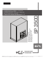 1
1
-
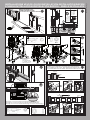 2
2
-
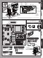 3
3
-
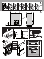 4
4
-
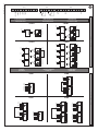 5
5
-
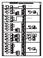 6
6
-
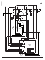 7
7
-
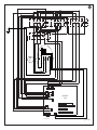 8
8
-
 9
9
-
 10
10
-
 11
11
-
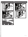 12
12
-
 13
13
-
 14
14
-
 15
15


in altre lingue
- English: BFT SP3500 User manual
Documenti correlati
-
BFT SP 3500 Manuale del proprietario
-
-
-
-
-
-
-
-
-
Altri documenti
-
CAME BQ810AS-BQ815AS-BE820AS-BE825AS Guida d'installazione
-
Tecnosystemi SMART SIRIO programmable thermostat Manuale del proprietario
-
Lika SBK Manuale utente
-
 Politec Parvis Solar SMA Technical Manual
-
 Beninca VNM Guida utente
-
 Beninca VNME Guida utente
-
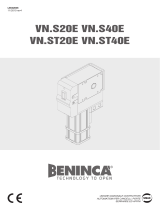 Beninca VNSE Guida utente
-
Kenwood NXR-1800 Manuale utente


