EnGenius ENH202 Manuale utente
- Categoria
- Punti di accesso WLAN
- Tipo
- Manuale utente
Questo manuale è adatto anche per

WIRELESS ACCESS POINT / CLIENT BRIDGE
Model: ENH202
User Manual
Version: 2.0

Table of Contents
1 PRODUCT OVERVIEW ...................................................................................................................................................... 6
1.1 FEATURES ...................................................................................................................................................................... 6
1.2 BENEFITS ....................................................................................................................................................................... 7
1.3 PACKAGE CONTENTS ...................................................................................................................................................... 9
1.4 SYSTEM REQUIREMENT .................................................................................................................................................. 9
1.5 HARDWARE OVERVIEW .................................................................................................................................................. 9
1.6 UNDERSTANDING THE ENH202 LEDS.......................................................................................................................... 10
2 INSTALLATION ................................................................................................................................................................ 11
2.1 PRE-INSTALLATION GUIDELINES .................................................................................................................................... 11
2.2 INSTALLING THE ENH202 ............................................................................................................................................ 11
3 WIRELESS NETWORK MODES ..................................................................................................................................... 13
3.1 ACCESS POINT MODE .................................................................................................................................................. 13
3.2 ACCESS POINT WITH WDS FUNCTION MODE ............................................................................................................... 14
3.3 CLIENT BRIDGE MODE ................................................................................................................................................. 15
3.4 WDS BRIDGE MODE ................................................................................................................................................... 16
3.5 CLIENT ROUTER MODE ................................................................................................................................................ 17
4 CONFIGURING YOUR COMPUTER FOR TCP/IP ........................................................................................................ 18
4.1 CONFIGURING MICROSOFT WINDOWS 7 ...................................................................................................................... 18
4.2 CONFIGURING MICROSOFT WINDOWS VISTA ................................................................................................................ 20
4.3 CONFIGURING MICROSOFT WINDOWS XP .................................................................................................................... 21
4.4 CONFIGURING APPLE MAC OS X ................................................................................................................................. 22
4.5 LOGGING INTO THE ENH202 ....................................................................................................................................... 23
5 STATUS .............................................................................................................................................................................. 25
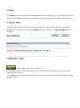
5.1 SAVE / LOAD ............................................................................................................................................................... 25
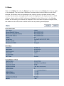
5.2 MAIN ......................................................................................................................................................................... 26
5.3 WIRELESS CLIENT LIST ................................................................................................................................................. 27
5.4 SYSTEM LOG ............................................................................................................................................................... 27
5.5 CONNECTION STATUS .................................................................................................................................................. 28
5.6 DHCP CLIENT TABLE ................................................................................................................................................... 28
6 SYSTEM ............................................................................................................................................................................. 29
6.1 SWITCHING THE OPERATION MODE .............................................................................................................................. 29
7 WIRELESS CONFIGURATION ........................................................................................................................................ 30
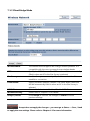
7.1 WIRELESS SETTINGS..................................................................................................................................................... 30
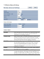
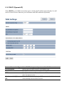
7.1.1 Access Point Mode ........................................................................................................................................ 30
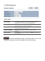
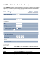
7.1.2 Client Bridge Mode ....................................................................................................................................... 33

7.1.3 WDS Bridge Mode ......................................................................................................................................... 35
7.1.4 Client Router Mode ....................................................................................................................................... 37
7.2 WIRELESS SECURITY SETTINGS ...................................................................................................................................... 39
7.2.1 WEP ................................................................................................................................................................ 39
7.2.2 WPA-PSK ....................................................................................................................................................... 40
7.2.3 WPA2-PSK ..................................................................................................................................................... 41
7.2.4 WPA-PSK Mixed ............................................................................................................................................ 42
7.2.5 WPA................................................................................................................................................................ 43
7.2.6 WPA2 ............................................................................................................................................................. 44
7.2.7 WPA Mixed .................................................................................................................................................... 45
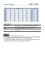
7.3 WIRELESS ADVANCED SETTINGS ................................................................................................................................... 46
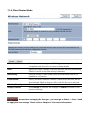
7.4 WIRELESS MAC FILTER ................................................................................................................................................ 48
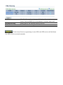
7.5 WDS LINK SETTINGS ................................................................................................................................................... 49
8 LAN SETUP ....................................................................................................................................................................... 50
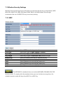
8.1 IP SETTINGS ................................................................................................................................................................ 50
8.2 SPANNING TREE SETTINGS ........................................................................................................................................... 51
9 ROUTER SETTINGS ......................................................................................................................................................... 52
9.1 WAN SETTINGS .......................................................................................................................................................... 52
9.1.1 Static IP .......................................................................................................................................................... 52
9.1.2 DHCP (Dynamic IP) ...................................................................................................................................... 54
9.1.3 PPPoE (Point-to-Point Protocol over Ethernet) .......................................................................................... 56
9.1.4 PPTP (Point-to-Point Tunneling Protocol) .................................................................................................. 58
9.2 LAN SETTINGS (ROUTER MODE) .................................................................................................................................. 60
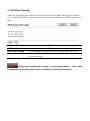
9.3 VPN PASS THROUGH .................................................................................................................................................. 61
9.4 PORT FORWARDING..................................................................................................................................................... 62
9.5 DMZ.......................................................................................................................................................................... 63
10 MANAGEMENT SETTINGS ......................................................................................................................................... 64
10.1 ADMINISTRATION ...................................................................................................................................................... 64
10.2 MANAGEMENT VLAN ............................................................................................................................................... 65
10.3 SNMP SETTINGS ...................................................................................................................................................... 66
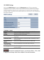
10.4 BACKUP/RESTORE SETTINGS ...................................................................................................................................... 67
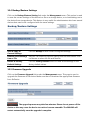
10.5 FIRMWARE UPGRADE ................................................................................................................................................. 67
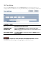
10.6 TIME SETTINGS .......................................................................................................................................................... 68
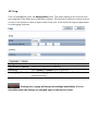
10.7 LOG .......................................................................................................................................................................... 69
10.8 DIAGNOSTICS ............................................................................................................................................................ 70
11 NETWORK CONFIGURATION EXAMPLES ............................................................................................................... 71
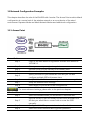
11.1 ACCESS POINT .......................................................................................................................................................... 71
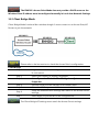
11.2 CLIENT BRIDGE MODE ............................................................................................................................................... 72
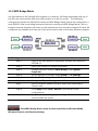
11.3 WDS BRIDGE MODE ................................................................................................................................................. 73

11.4 CLIENT ROUTER MODE .............................................................................................................................................. 74
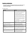
APPENDIX A – TROUBLESHOOTING ............................................................................................................................. 75
A.1 PROBLEM SOLVING ..................................................................................................................................................... 75
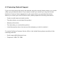
A.2 CONTACTING TECHNICAL SUPPORT .............................................................................................................................. 76
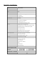
APPENDIX B – SPECIFICATIONS ..................................................................................................................................... 77
APPENDIX C – GLOSSARY ................................................................................................................................................ 79
APPENDIX D – STATEMENTS OF CONFORMITY ......................................................................................................... 84
D.1 – FEDERAL COMMUNICATION COMMISSION INTERFERENCE STATEMENT ......................................................................... 84
D.2 – INDUSTRY CANADA STATEMENT ................................................................................................................................ 85
D.3 – EUROPE DECLARATION OF CONFORMITY ................................................................................................................... 86

About This Document
This document is written by EnGenius Inc. EnGenius Inc. the reserves the right to change this
document without notice and all rights are reserved. This document can only be used for the
configuration of EnGenius products.
This document is to characterize the EnGenius ENH202 Wireless Access Point & Client
Bridge. Please read the document carefully before setting up the ENH202. Any damage which
is caused by inappropriate use will not be covered under the warranty.
Formats
This document uses following symbols to indicate and highlight special messages.
Caution: This symbol represents a vital message and it is critical for the device
or settings.
Note: This symbol represents an important message for the settings.
Tip: This symbol represents an alternative choice that can save time or
resources.
Before you start__________________________________________________
The following equipment is required to setup the ENH202:
1. (1) Computer/Notebook and Internet access.
2. (2) Ethernet cables.
3. (1) EnGenius ENH202.
The equipment listed above is only for configuration of the ENH202, you will
need additional equipment to connect to the Internet and configuration will depend on your
current network infrastructure. Please refer to Chapter 2 for more information.

1 Product Overview
Thank you for using the ENH202. It is a powerful and enhanced business-class product with 4
multi-functions: Access Point, Client Bridge, WDS, and Client Router.
EnGenius’ ENH202 uses the latest wireless standard, 802.11n, which allows for faster wireless
throughput. The ENH202 affords a great advantage to minimize the time and cost which is
required to expand your network. It operates at 2.4GHz and is also backwards compatible with
802.11b/g networking equipment.
The ENH202 is easy to install almost anywhere with included proprietary Power over Ethernet
adapter for quick outdoor installation. In addition, the ENH202 can manage power level
control, and it features narrow bandwidth selection, traffic shaping and real-time RSSI
indication. The ENH202 fully supports wireless encryption including Wi-Fi Protected Access
(WPA-PSK/WPA2-PSK), (64/128/152)-bit WEP Encryption, and IEEE 802.1x with RADIUS.
Additionally, the ENH202 is an ideal choice to pair with the ENH202 in an Access Point – Client
Bridge or WDS Bridge – WDS Bridge topology.
The ENH202 utilizes a proprietary PoE adapter. Only use the supplied PoE
adapter. Damage may occur if another PoE adapter is used.
1.1 Features
The following list describes the design and scope of the ENH202 made possible through the
power and flexibility of wireless LANs:
a) Difficult-to-wire environments
There are many situations where wires cannot be laid easily. For example, historic
and older buildings as well as open areas and cross-street architectures make the
installation of LANs either impossible or very expensive.
b) Temporary workgroups
Consider situations in parks, athletic arenas, exhibition centers, disaster-recovery,
temporary offices and construction sites where one wants a temporary WLAN
established and removed at a future date. The ENH202 is easy to place into and
remove from production.
c) The ability to access real-time information
Doctors and nurses, point-of-sale employees, and warehouse workers can access
real-time information while dealing with patients, serving customers, and
processing information.

d) Frequently altered environments
Show rooms, meeting rooms, retail stores, and manufacturing sites are prime
examples where frequently rearranged workplaces are suited for wireless LANs.
e) Wireless extensions of Ethernet networks
Network managers in dynamic environments can minimize the overhead caused by
moves, extensions to networks, and other changes by utilizing wireless LANs.
f) Wired LAN backup
Network managers may implement wireless LANs to provide redundancy for
mission-critical applications which are implemented on wired networks.
g) Training and educational facilities
Training sites at corporations and students at universities use wireless connectivity
to afford access to information, information exchanges, and learning.
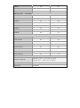
1.2 Benefits
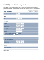
Access Point Mode Use this feature to setup the access point’s configuration
Features
High Speed Data Rate
Up to 300 Mbps
Capable of handling heavy data payloads such as HD video
streaming
High Output Power -
up to 29 dBm
Extended range and excellent coverage
IEEE 802.11b/g/n
Compliant
Fully interoperable with IEEE 802.11 b/g/n compliant devices
Multi-Function Users can use different modes in various environments
Support RSSI
Indicator (CB mode)
Users can select the best signal to connect with AP efficiently
Power-over-Ethernet
Flexible Access Point locations and cost savings (Note: The
ENH202 includes a proprietary PoE adapter.)
Support Multi-SSID
function (4 SSID) in
AP mode
Allow clients to access different networks through a single
access point and assign different policies and functions for each
SSID
WPA2/WPA/ WEP/
IEEE 802.1x support
Full support for all types of current wireless security standards
MAC address filtering
in AP mode
Ensure secure network by enforcing network access control lists
PPPoE/PPTP function
support (CR mode)
Easy to access Internet via ISP service authentication
SNMP Remote
Configuration
Management
Allow administrators to remotely configure or manage the
Access Point.
QoS (WMM) support Enhance user performance and density

information. It supports transmit power and channel adjustments.
Clients can access the network with different regulatory settings
and automatically change to the local regulations.
Client Bridge Mode Use this feature to connect to an Access Point, enabling WAN
sharing.
WDS Mode Use this feature to link multiple APs in a network; All associated
clients from any AP can communicate with each other like in
ad-hoc mode.
Client Router Mode Clients connect wirelessly to an AP and transmit data through AP
to access the Internet.
Multiple SSIDs ENH202 supports up to 4 SSIDs on your access point. The
following options can be set to each SSID:
- Public or private SSID
- Authentication
- VLAN identifier
- RADIUS accounting identifier
- Profile isolation for infrastructure network
VLAN Specify a VLAN number for each SSID to separate the services
among clients.
QoS Use this feature to limit the incoming or outgoing throughput.
Wi-Fi Protected Access Wi-Fi Protect Access is a standard-based interoperable security
enhancement that increases the level of data protection and
access control for existing and future wireless LAN systems. It is
compatible with IEEE 802.11i standard. WPA leverages TKIP and
802.1X for authenticated key management.

1.3 Package Contents
Open the package carefully, and make sure that none of the items listed below are missing.
Do not discard the packing materials; in case of return, the unit must be shipped in its original
packaging.
(1) Wireless Access Point / Client Bridge (ENH202)
(1) 24V/1.0A Power Adapter
(1) PoE Injector (EPE-24R)
(1) Mounting Kit with Mast-Mount Strap Special Screw Set
(1) QIG
(1) CD (User Manual)
Using a power adapter other than the one included with the ENH202 may
cause damage to the device.
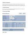
1.4 System Requirement
The following conditions are the minimum system requirements.
A computer with an Ethernet interface and operating under Windows XP, Vista, 7 or
Linux.
An Internet browser that supports HTTP and JavaScript.
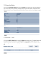
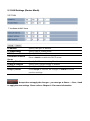
1.5 Hardware Overview
Physical Interface - 1 x 10/100 LAN Port with PoE support
- 1 x 10/100 LAN port
- 1 x Reset button
Maximum Wireless Data rate - 300 Mbps
LEDs status - Power Status
- LAN (10/100Mbps)
- WLAN (Wireless is enabled)
- 3 x Link Quality (Client Bridge mode)

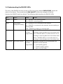
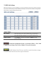
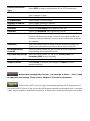
1.6 Understanding the ENH202 LEDs
The rear of the ENH202 has two groups of LEDs. One group, labeled INDICATORS, shows the
status of the device. The second group, LINK QUALITY, shows the strength of the link
between the ENH202 and the network. The following table describes the ENH202 LEDs.
LED Color Mode Status
Power
Green
OFF= ENH202 is not receiving power.
ON= ENH202 is receiving power.
LAN
Green(Main)
Orange(Secondary)
OFF = ENH202 is not connected to the network.
ON = ENH202 is connected to the network, but not sending or
receiving data.
Blink = ENH202 is sending or receiving data.
WLAN
Green
Access Point
or Client
Bridge Mode
OFF = ENH202 radio is off and the device is not
sending or receiving data over the wireless LAN.
ON = ENH202 radio is on, and the device is not
sending or receiving data over the wireless LAN.
Blink = ENH202 radio is on, and the device is
sending or receiving data over the wireless LAN.
Link Quality
See Status column
Access Point
or Client
Bridge Mode
Shows the strength of the link between the
ENH202 and the network.
G = good quality (green).
Y = medium quality (yellow).
R = poor or no link (red).

2 Installation
This chapter describes how to install the ENH202.
Only experienced installation professionals who are familiar with local building and
safety codes and, wherever applicable, are licensed by the appropriate government regulatory
authorities should install the ENH202.
2.1 Pre-installation Guidelines
Select the optimal locations for the equipment using the following guidelines:
- The ENH202 should be mounted on a 1"- 4" pole. Its location should enable easy access
to the unit and its connectors for installation and testing.
- The higher the placement of the antenna, the better the achievable link quality.
- The antenna should be installed to provide a direct or near line of sight link with the base
station antenna. The antenna should be aligned to face the general direction of the base
station.
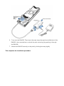
2.2 Installing the ENH202
To install the ENH202, use the following procedure to mount the device on a pole and refer to
the figure below.
1. The bottom of the ENH202 is a removable cover. Grab the cover and push down
slightly while pulling it backward to remove the cover.
2. Insert a standard Ethernet cable into the RJ-45 port labeled MAIN LAN.
3. Slide the cover back to seal the bottom of the ENH202.
4. Remove the power cord and PoE injector from the box and plug the power cord
into the DC port of the PoE injector.
Only use the power adapter supplied with the ENH202. Using a different
power adapter might damage the ENH202.
5. Plug the other side of the Ethernet cable in Step 3 into the PoE port of the PoE
injector. When you finish Step 5, the installation will resemble the following picture.

6. Turn over the ENH202. Then insert the mast strap through the middle hole of the
ENH202. Use a screwdriver to unlock the pole-mounting ring putting it through
the ENH200.
7. Mount the ENH202 securely to the pole by locking the strap tightly.
This completes the installation procedure.

3 Wireless Network Modes
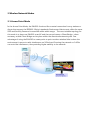
3.1 Access Point Mode
In the Access Point Mode, the ENH202 functions like a central connection for any stations or
clients that support the IEEE 802.11b/g/n standards. Stations and clients must utilize the same
SSID and Security Password to associate while within range. The most suitable topology for
this mode is to have one ENH202 as an AP and the second one as a Client-Bridge – when
necessary a third Client-Bridge can be place within the directional antenna’s path. One
advantage of using the ENH202 to create point-to-point outdoor wireless links is when the
environment is prone to radio interference on 5GHz band. Running the network on 2.4GHz
can avoid the interference, thus providing higher stability to the network.

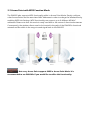
3.2 Access Point with WDS Function Mode
The ENH202 also supports WDS functionality while in Access Point Mode. Simply configure
other Access Points and the associated MAC addresses in order to enlarge the wireless area by
enabling WDS Link Settings. WDS functionality can support up to 8 different AP MAC
addresses. Please note that this mode is rarely used due to the nature of directional antennae.
Consequently, the wireless clients need to be located in the path of the ENH202’s directional
antenna and be within in the range to send signal back to the ENH202.
Not every Access Point supports WDS in Access Point Mode. It is
recommended to use ENH202s if you would like to utilize this functionality.

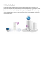
3.3 Client Bridge Mode
In the Client Bridge Mode, the ENH202 functions like a wireless client, connecting to an
Access Point wirelessly and enabling Internet connectivity wherever you want. Use Site Survey
function to scan all of the Access Points within range and configure the SSID and Security
Password to associate with it. With Client Bridge Mode, the ENH202 works as long range
2.4GHz wireless-Ethernet Bridge in order to provide a 2.4GHZ link between the access point
and networked clients.

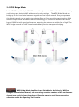
3.4 WDS Bridge Mode
In the WDS Bridge Mode, the ENH202 can wirelessly connect different local area networks by
configuring each device’s MAC address and security settings. The WDS Bridge Mode can
bridge up to four local wired networks together as one logical network. Every computer on
this logical network can see each other, sharing files as if they are in the same location. With
600mW output power and MIMO antenna technology, the connection distance can extend
beyond 1000 feet with good performance, assuming the antenna are within line of sight. The
WDS bridge network is a MAC-based network that provides transparent bridging.
WDS Bridge Mode is unlike Access Point Mode. APs linked by WDS are
using the same wireless channel, and connecting excessive numbers of APs on the same
channel may result in lower throughput. Please be aware to avoid loop connections;
otherwise enable the Spanning Tree Function.

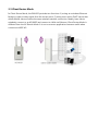
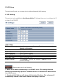
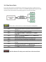
3.5 Client Router Mode
In Client Router Mode, the ENH202 provides two functions: 1) acting as a wireless-Ethernet
Bridge in order to relay signal from the access point; 2) acting as an active DHCP server that
allows WLAN clients to share the same wireless network connection. Ideally, have clients
wirelessly connect to an AP/WISP and connect to LANs via Ethernet. Client Router Mode is
different from the AP Router Mode. It is not a common application however useful when
connects to WISP AP.

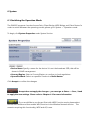
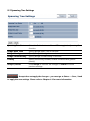
4 Configuring Your Computer for TCP/IP
This chapter describes how to configure the TCP/IP settings on a computer that will be used
to configure the ENH202. Because the default operating mode is Client Bridge, an IP address
will not be assigned to the computer/notebook. Therefore, follow the steps below to assign
an IP address to a client’s Ethernet adapter.
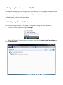
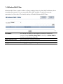
4.1 Configuring Microsoft Windows 7
Use the following procedure to configure a computer running Microsoft Windows 7.
1. In the Start menu search box, type: ncpa.cpl
2. When the Network Connections List appears, right-click the Local Area Connection icon
and click Properties.

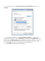
3. In the Networking tab, click Internet Protocol Version 4 (TCP/IPv4), and then click
Properties.
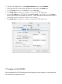
4. In the properties dialog box, click Use the following IP address: to configure your
computer for Static TCP/IP. Enter an IP address (i.e. 192.168.1.10), the subnet mask of the
ENH202, and the default gateway which is the ENH202’s IP address, 192.168.1.1. Note: the
subnet mask must match that of the ENH202 and the IP address must be on that subnet.
5. Click the OK button to save your changes and close the dialog box.
6. Click the OK button again to save your changes.

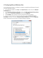
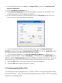
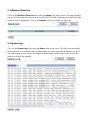
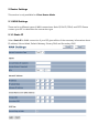
4.2 Configuring Microsoft Windows Vista
Use the following procedure to configure a computer running Microsoft Windows Vista with
the default Windows interface.
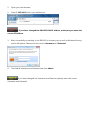
1. On the Windows taskbar, click Start, click Control Panel, and then select the Network
and Internet icon.
2. Click View Network Status and tasks and then click Manage Networks Connections.
3. Right-click the Local Area Connection icon and click Properties.
4. Click Continue. The Local Area Connection Properties dialog box appears.
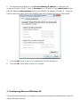
5. In the Local Area Connection Properties dialog box, verify that Internet Protocol
(TCP/IPv4) is checked. Then select Internet Protocol (TCP/IPv4) and click the Properties
button. The Internet Protocol Version 4 Properties dialog box appears.
La pagina sta caricando ...
La pagina sta caricando ...
La pagina sta caricando ...
La pagina sta caricando ...
La pagina sta caricando ...
La pagina sta caricando ...
La pagina sta caricando ...
La pagina sta caricando ...
La pagina sta caricando ...
La pagina sta caricando ...
La pagina sta caricando ...
La pagina sta caricando ...
La pagina sta caricando ...
La pagina sta caricando ...
La pagina sta caricando ...
La pagina sta caricando ...
La pagina sta caricando ...
La pagina sta caricando ...
La pagina sta caricando ...
La pagina sta caricando ...
La pagina sta caricando ...
La pagina sta caricando ...
La pagina sta caricando ...
La pagina sta caricando ...
La pagina sta caricando ...
La pagina sta caricando ...
La pagina sta caricando ...
La pagina sta caricando ...
La pagina sta caricando ...
La pagina sta caricando ...
La pagina sta caricando ...
La pagina sta caricando ...
La pagina sta caricando ...
La pagina sta caricando ...
La pagina sta caricando ...
La pagina sta caricando ...
La pagina sta caricando ...
La pagina sta caricando ...
La pagina sta caricando ...
La pagina sta caricando ...
La pagina sta caricando ...
La pagina sta caricando ...
La pagina sta caricando ...
La pagina sta caricando ...
La pagina sta caricando ...
La pagina sta caricando ...
La pagina sta caricando ...
La pagina sta caricando ...
La pagina sta caricando ...
La pagina sta caricando ...
La pagina sta caricando ...
La pagina sta caricando ...
La pagina sta caricando ...
La pagina sta caricando ...
La pagina sta caricando ...
La pagina sta caricando ...
La pagina sta caricando ...
La pagina sta caricando ...
La pagina sta caricando ...
La pagina sta caricando ...
La pagina sta caricando ...
La pagina sta caricando ...
La pagina sta caricando ...
La pagina sta caricando ...
La pagina sta caricando ...
La pagina sta caricando ...
La pagina sta caricando ...
La pagina sta caricando ...
-
 1
1
-
 2
2
-
 3
3
-
 4
4
-
 5
5
-
 6
6
-
 7
7
-
 8
8
-
 9
9
-
 10
10
-
 11
11
-
 12
12
-
 13
13
-
 14
14
-
 15
15
-
 16
16
-
 17
17
-
 18
18
-
 19
19
-
 20
20
-
 21
21
-
 22
22
-
 23
23
-
 24
24
-
 25
25
-
 26
26
-
 27
27
-
 28
28
-
 29
29
-
 30
30
-
 31
31
-
 32
32
-
 33
33
-
 34
34
-
 35
35
-
 36
36
-
 37
37
-
 38
38
-
 39
39
-
 40
40
-
 41
41
-
 42
42
-
 43
43
-
 44
44
-
 45
45
-
 46
46
-
 47
47
-
 48
48
-
 49
49
-
 50
50
-
 51
51
-
 52
52
-
 53
53
-
 54
54
-
 55
55
-
 56
56
-
 57
57
-
 58
58
-
 59
59
-
 60
60
-
 61
61
-
 62
62
-
 63
63
-
 64
64
-
 65
65
-
 66
66
-
 67
67
-
 68
68
-
 69
69
-
 70
70
-
 71
71
-
 72
72
-
 73
73
-
 74
74
-
 75
75
-
 76
76
-
 77
77
-
 78
78
-
 79
79
-
 80
80
-
 81
81
-
 82
82
-
 83
83
-
 84
84
-
 85
85
-
 86
86
-
 87
87
-
 88
88


EnGenius ENH202 Manuale utente
- Categoria
- Punti di accesso WLAN
- Tipo
- Manuale utente
- Questo manuale è adatto anche per
in altre lingue
- English: EnGenius ENH202 User manual
Documenti correlati
Altri documenti
-
Philips SNN6600/00 Manuale utente
-
Zoom Network Router 4410A Manuale utente
-
Allnet ALL02850N Manuale del proprietario
-
ZyXEL WAP6405 Manuale utente
-
Cisco Linksys WRT320N Manuale utente
-
-
Philips SNU6600/00 Manuale utente
-
Dell Wireless 1515 Wireless-N WLAN Card Users Guide Manuale del proprietario
-
Vivanco WLAN ROUT 54-N Manuale del proprietario
-
ZyXEL WAP6804 Guida utente