Carel Datalogger Manuale utente
- Categoria
- Misurazione, test
- Tipo
- Manuale utente

Datalogger
User manual
Manuale d’uso
Einbau und Bedienungsanleitung
Manuel d’utilisation
Manual de utilización

Smaltimento del prodotto
L’apparecchiatura (o il prodotto) deve essere oggetto di raccolta separata in conformità alle vigenti normative locali in materia di smaltimento.
Disposal of the product
The appliance (or the product) must be disposed of separately in accordance with the local waste disposal legislation in force.
Élimination du produit
L’équipement (ou le produit) doit faire l’objet d’un ramassage particulier en conformité avec les normes en vigueur locales en matière d’élimination des
déchets.
Entsorgung des Produktes
Das Gerät (oder Produkt) muss im Mülltrennungsverfahren in Übereinstimmung mit den örtlichen Entsorgungsnormen entsorgt werden.
Reciclage del producto
Los componentes (o el producto) deben ser tratados separadamente en conformidad a la normativa local vigente en materia de reciclaje.
GB
F
D
ES
AVVERTENZE IMPORTANTI
Il prodotto CAREL è un prodotto avanzato, il cui funzionamento è specifi cato nella documentazione tecnica fornita col prodotto o scaricabile, anche
anteriormente all’acquisto, dal sito internet www.Carel.com. Il cliente (costruttore, progettista o installatore dell’equipaggiamento fi nale) si assume ogni
responsabilità e rischio in relazione alla fase di confi gurazione del prodotto per il raggiungimento dei risultati previsti in relazione all’installazione e/o
equipaggiamento fi nale specifi co.
La mancanza di tale fase di studio, la quale è richiesta/indicata nel manuale d’uso, può generare malfunzionamenti nei prodotti fi nali di cui CAREL non potrà
essere ritenuta responsabile. Il cliente fi nale deve usare il prodotto solo nelle modalità descritte nella documentazione relativa al prodotto stesso.
La responsabilità di CAREL in relazione al proprio prodotto è regolata dalle condizioni generali di contratto CAREL editate nel sito www.Carel.com e/o da specifi ci
accordi con i clienti.
IMPORTANT WARNINGS
The CAREL product is a state-of-the-art product, whose operation is specifi ed in the technical documentation supplied with the product or can be downloaded,
even prior to purchase, from the website www.Carel.com. The client (builder, developer or installer of the fi nal equipment) assumes every responsibility and
risk
relating to the phase of confi guration the product in order to reach the expected results in relation to the specifi c fi nal installation and/or equipment. The lack
of such phase of study, which is requested/indicated in the user manual, can cause the fi nal product to malfunction of which CAREL can not be held
responsible.
The fi nal client must use the product only in the manner described in the documentation related to the product itself. The liability of CAREL in relation to its
own product is regulated by CAREL’s general contract conditions edited on the website www.Carel.com and/or by specifi c agreements with clients.
AVERTISSEMENTS IMPORTANTS
Le produit CAREL est un produit avancé dont le fonctionnement est spécifi é dans la documentation technique fournie avec le produit ou téléchargeable, même
avant l’achat, du site Internet www.carel.com. Le client (constructeur, concepteur ou installateur de l’équipement fi nal) assume toutes les responsabilités et
risques quant à la confi guration du produit pour l’obtention des résultats prévus quant à l’installation et/ou à l’équipement fi nal spécifi que.
L’absence de cette phase d’étude qui est requise/indiquée dans le manuel d’instructions peut provoquer des dysfonctionnements des produits fi nals dont CAREL
ne pourra en aucun cas être jugée responsable. Le client fi nal doit utiliser le produit exclusivement selon les modes décrits dans la documentation correspondant
au produit. La responsabilité de CAREL en ce qui concerne son produit est réglée par les conditions générales de contrat CAREL publiées sur le site www.carel.
com et/ou par des accords spécifi ques stipulés avec les clients.
WICHTIGE HINWEISE
Das CAREL Produkt ist ein Produkt nach dem neuesten Stand der Technik, dessen Betriebsanleitungen in den dem Produkt beiliegenden technischen
Spezifi kationen enthalten sind oder - auch vor dem Kauf - von der Internetseite www.carel.com heruntergeladen werden können.
Der Kunde (Hersteller, Planer oder Installateur der Endausstattung) übernimmt jede Haftung und Risiken in Bezug auf die Produktkonfi guration zur Erzielung
der bei der Installation und/oder spezifi schen Endausstattung vorgesehenen Resultate. Die Unterlassung dieser Phase, die im Benutzerhandbuch verlangt/
angegeben ist, kann zu Funktionsstörungen der Endprodukte führen, für welche CAREL nicht verantwortlich gemacht werden kann. Der Endkunde darf das
Produkt nur auf die in den Produktspezifi kationen beschriebenen Weisen verwenden. Die Haftung CARELS für die eigenen Produkte ist von den allgemeinen
CAREL Vertragsbedingungen (siehe Internetseite www.carel.com) und/oder durch spezifi sche Vereinbarungen mit den Kunden geregelt.
ADVERTENCIAS IMPORTANTES
El producto CAREL es un producto avanzado, cuyo funcionamiento está especifi cado en la documentación técnica suministrada con el producto o descargable,
incluso antes de la compra, desde el sitio de internet www.carel.com. El cliente (constructor, proyectista o instalador del equipo fi nal) asume toda la
responsabilidad y el riesgo relativos a la fase de confi guración del producto con el fi n de los resultados previstos en relación a la instalación y/o equipamiento
fi nal específi co.
Pasar por alto dicha fase de estudio, la cual es solicitada/indicada en el manual de uso, puede generar funcionamientos anómalos en los productos fi nales,
de los cuales no se podrá responsabilizar a CAREL. El cliente fi nal debe utilizar el producto sólo en las modalidades descritas en la documentación relativa al
producto en sí.
La responsabilidad de CAREL en relación a su producto propio está regulada por las condiciones generales del contrato de CAREL editadas en el sitio www.carel.
com y/o por los acuerdos específi cos con los clientes.
GB
F
D
ES

ENGLISH
User manual
Contents
Introduction ..................................................................................................................................................... 5
Mounting ......................................................................................................................................................... 5
Connection ...................................................................................................................................................... 7
Power ON ......................................................................................................................................................... 7
Programming .................................................................................................................................................. 8
Description of the buttons ............................................................................................................................. 8
• TEMPERATURE Button ................................................................................................................................ 8
• CLOCK Button ............................................................................................................................................ 10
• ENTER Button ............................................................................................................................................. 11
• ALARM Button ............................................................................................................................................ 13
Tab. 1 - Alarm codes ..................................................................................................................................... 15
Tab. 2 - Symbol description ......................................................................................................................... 15
Tab. 3 - Default parameters .......................................................................................................................... 15
Specifi cations for the Download ................................................................................................................. 16
Example of data print by Download ................................................................................................................ 17
Example of graph print by Download .............................................................................................................. 20
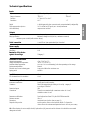
Technical specifi cations .............................................................................................................................. 21
Appendix - Periodical verifi cation procedures .......................................................................................... 22
Verifi cation of the internal clock ...................................................................................................................... 26


ENGLISH
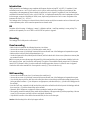
Introduction
CAREL presents the new Datalogger range compliant with European directives 89/108/EEC, 92/2/EEC, EC regulation 37/2005
and Italian decree laws no. 110 of 27/01/92 and no. 493 of 25/09/95, which require the recording and conservation of data
corresponding to the temperature of frozen foodstuffs for at least one year. As regards EC regulation 37/2005, the Datalogger
model fi tted with standard Carel NTC probe, code DLOGNTC015, is compliant with standard EN 12830 on temperature recorders
for the transport, storage and distribution of chilled, frozen, deep-frozen/quick-frozen food and ice cream. Designation of the
instrument: EN 12830, S, A, 1. -35T30 °C.
The Datalogger of the Carel range is an electrical device offered in various models, that can monitor and record data read by two
or four temperature probes. In this manual we present the two-channel model.
Kit
Description of the kit content: 1 Datalogger, 1 manual, 1 calibration certifi cate, 1 small bag containing 5 screws, packing. The
probes are sold separately. The use of CAREL code DLOGNTC015 probes is suggested.
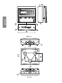
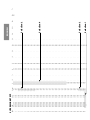
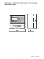
Mounting
The Datalogger can be both panel or wall mounted.
Panel mounting
• Make a hole in the panel with the following dimensions: 182x153mm.
• Unscrew the two frontal screws (see a, b) and take out the central door (c).
• Unscrew the two screws (d, e) that keep connected the lower and frontal cover of the Datalogger and separate the two parts.
• Make two holes in the back part (in the perforated part- f, g).
• Join the back part and the front, with the panel in between, and fi x the whole with the two screws (dimensions: 4x10mm) that
are contained in the kit.
N.B. It is necessary to remove the two upper fi xing teeth (h) of the frontal part before the panel insertion. Make the hole in the
back upper (l) or lower part (i) to allow the cable passage. The pitches of the established threads ranges from PG9 (diameter:
16mm) to PG21 (diameter: 29mm). In order to make easier the drilling operation, the use of a drill and a cutter is suggested.
Connect the cables to the terminal block. Screw again the screws (d, e). Then screw the door (c).
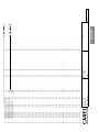
Wall mounting
• Unscrew the two frontal screws (see a, b) and remove the central door (c).
• Unscrew the two screws (d, e) that keep connected the lower and frontal cover of the Datalogger and separate the two parts.
• Once decided where to pass the cable duct or the cables (from above or from below) and then after making the proper holes
(in the part drilled in advance - i, l) for cablepresses and pipepresses, make three holes (m, n, o) both in the Datalogger and in
the wall itself.
• Insert the “wall” nugs, contained in the kit, into the holes made in the wall and then fi x the back part of the Datalogger with the
three screws (m, n, o) and the relevant Orings to the wall itself.
• Afterwards, fi x the cablepresses or pipepresses before mounting the frontal part of the Datalogger.
• Subsequently, mount the frontal part, being careful with the positioning of the upper teeth (h) and the proper fi xing of the two
screws (d, e) (do not press excessively in order to avoid plastic deformation).
• Only after the connection of the cables to the terminal block, the door can be shut again.
Attention: After the wiring fi x the cables by the proper cable-tie.

sensor 2sensor 1
a
b
c
d
e
h
i
l
ENGLISH
120
100
f
g
m
n
o
i
l
upper part
lower part
back
side

ENGLISH
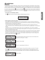
Important:
1. Avoid mounting the instrument in rooms with the following characteristics:
- wide and fast fl uctuations of the ambient temperature;
- relative humidity exceeding 80%;
- exposure to direct water jets under pressure;
- remarkable magnetic and/or radio frequency interferences (e. g., of transmitting antennas).
2. Utilize lugs suited to the terminal block in use. Loosen each screw and insert into them the lugs, afterwards tighten the screws.
Finally, gently pull the cables to check their correct clamping.
3. Separate as much as possible the cables of the probe signals and of the digital inputs from the power and inductive load
cables in order to avoid possible electromagnetic noises. Absolutely do not introduce into the same cable ducts (included
those of the electric cables) power cables and probe cables. Avoid the probe cables being installed close to power devices
(contactors, magnetothermals, or other devices). Reduce as much as possible the course of the probe cables in order to
prevent the occurrence of spiral courses enclosing power devices. To extend the probe cables, utilize cables with a minimum
section of 0.5 mm
2
at least.
4. Do not get near the electronic components mounted on the cards with your fi ngers in order to avoid stray
currents (extremely harmful) from the operator to the components themselves.
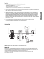
Connection
Caution: an improper power supply connection can seriously damage the system.
Power ON
When switched on, the instrument displays an introductive mask reporting the version of the software installed. After a few
seconds, the instrument enters the normal functioning mode, in which the read temperature and date are shown. At the fi rst
switching on, the operation parameters are those of default (see the table on page 15).
Once selected, the desired values of the parameters are stored and recalled at every successive Power ON.
If at the switching on the mask:
digital inputs
probes
dial
230 Vac~

3
6
5
2
4
1
ENGLISH
appears, it means that the instrument has undergone damages of the hardware type (see the ALARM section).
Programming
The instrument allows the display and storage of the temperature measured with, at most, two distinct probes (NTC). The stored
temperature is the instantaneous value detected at selectable time intervals (see mask 3). In addition to the two probe inputs, the
instrument is equipped with two clean digital outputs and one exchange-relay alarm digital output. It is possible to choose whether
to activate only one probe or both.
Each digital input is coupled with only one of the two probes. The keyboard consists of six buttons, four of which are provided with
back-lit LEDs.
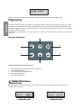
Description of the buttons
Function buttons provides an easy to use format
1 Recorded temperature and general information display button;
2 clock programming button;
3 buzzer silencing and alarm display button;
4/5 stored data scrolling buttons;
6 parameter selection button.
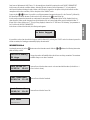
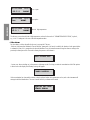
TEMPERATURE Button
TEMPERATURE Mode
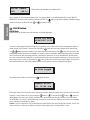
With a gentle pressure on the button, the main mask is displayed (also present at the switching on and during the normal
functioning of the instrument).
FLASH DOCTOR...
05/11/1996 12:53
+18.5°C ROOM1
05/11/1996 12:53
+18.5°C -12.5°C
2 confi gurated probes1 confi gurated probe

ENGLISH
Date, hour and alphanumeric fi eld (“Room 1” in the example) are selectable by entering the mode “MODIFY PARAMETERS”.
In the presence of particular conditions (alarms, defrosting) the unit of measure of the temperature (°C ) is being replaced
with a special character indicating the type of alarm or the cell state. As regards the description of the special characters and the
management of the alarm conditions, see the description of the “ALARMS” mode.
By pressing the
buttons it is possible to scroll the temperature data previously stored (i.e. the “historical”), followed by
the relevant possible alarm characters (in this mode the LED relevant to the
buttons lights up).
If at the storage moment the instrument was confi gurated for two probes, two temperature values will be displayed (only one
value otherwise). Other special characters show special situations such as a power supply failure, special character the letter “P”
(Power ON) in a time selection one “T” (Time) is being displayed, whereas one “D” indicates a “cell defrosting” (see parameters 6
and 7 in the mode “MODIFY PARAMETERS”.
In the absence of data of the historical, the following mask appears:
It is possible to select a date from which to begin to scroll the historical, by selecting the “CLOCK” mode. If no button is pressed for
at least one minute, the Datalogger automatically displays the main mask.
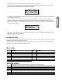
INFORMATION Mode
A prolonged pressure (5s) of the button enters the information mode. With the buttons the following information
masks are being scrolled:
Available Memory
352 days
Storage day number still available before the old ones are being overwritten. The maximum
available storage occurs after a Download.
Date and hour of the last alarm numeric code associated with the alarm (in the table no. 1
a list of codes is shown).
Date and hour of the last Download.
Date and hour of the last Power ON.
Operator Name.
No Data Logged
Last Alarm
10
02/05/96 15:42
Last Power On
02/05/96 12:42
Last Download
02/05/96 13:15
User Name
--------

ENGLISH
Serial number of the instrument and software version.
After a switching off, the last alarm information is lost. The “Operator Name” is selectable manually with the mode “MODIFY
PARAMETERS”, whereas the serial number and versions are fi xed. The
button, fi nally, allows regulating manually the display
contrast by pressing it simultaneously with
or (to darken or clear).
CLOCK Button
CLOCK Mode
A gentle pressure on the button causes the following mask display appearance:
The cursor is already positioned on the fi rst digit. It is now possible to select a date for the search of the temperature values at a
certain moment, in the “historical”: each pressure of the button
carries the cursor onto a different fi eld of date and hour.
The
buttons permit the variation of each singular digit. With a last pressure of the button, the search of the data
corresponding with the selected date. The search is successful if a datum is found with a date corresponding with to the selected
one or if there are two dates respectively preceding or following the selected one. In case of discontinuities in the date storage
(e.g.: after a solar/summer time selection), it is possible that one and the same date appears several times. In this case the search
start recognizes the less recent one. By pressing the
button, all the other ones are being circularly displayed. In the absence
of the searched datum or if, after fi nding a datum there are no other data to be shown, the following mask appears:
The prolonged pressure (about 3s) of the button
displays the mask:
for the rapid change of the summer time to the solar time and viceversa. When the summer time is selected and the solar time is
requested, 1 hour is added to the clock by pressing the
button (+1 ). If erroneously the button (-1 ), is pressed,
nothing happens. The same is true, with the due differences, in the reverse passage from the solar time to the summer time.
The modifi cation, if it occurred, is automatically being accepted by the instrument. If no button has been pressed, the instrument
returns to the main mask after about 1 minute.
Caution: if the LED coupled to the CLOCK button blinks, this means that the Clock chip is damaged and a backup “virtual” clock
has been activated, in order to go on with the recording. For further details see the “Accidental alarms” section.
Serial Number
150 (V2.2)
Search Log Data:
04/04/1995 11:12
No Data Logged
Summer/Solar
+1 15:42 -1

ENTER Button
PARAMETER MODIFICATION Mode
The access is possible through a prolonged pressure (about 3s) of the button. In this mode it is possible to select different
parameters of operative interest and to enter them a 4 digit numerical password is required (for default it is 0015). It is keyed in by
utilizing
and if it is correct, direct access to the “parameter” mask is allowed. Otherwise, after the message of “Wrong
Password”, the main mask is displayed again.
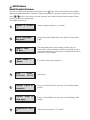
The modifi able parameters are:
Number of confi gurated probes (1 or 2). Default 1.
Language being utilized (English, Italian, French, Spanish, German). Default
English.
Time interval between two successive samplings. (Default 15 min). If a
reduced value is selected, not allowing a continuous recording for one year, or
an anomalous interval, the user is informed by a message (beside the selected
value the word “Warn.!” appears).
It is possible to assign a name to the probe 1.
Date and hour.
Door no.1 switch (Disabled, norm. open, norm. closed, defrosting). Default
Disabled.
Door no. 2 switch (Disabled, norm. open, norm. closed, defrosting). Default
Disabled.
Temperature unit of measure (°C, °F). Default °C.
1
2
3
4
5
6
7
8
Number of Probes
1
User Language
English
Sample Time
15 min
Text Probe 1
Room1
Date Time
05/11/96 12:53
Digital Input n1
Disabled
Temperature Unit
°C
Digital Input n2
Norm.Open

ENGLISH
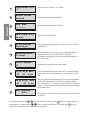
Temperature unit of measure (°C, °F). Default °C.
Buzzer (Enabled, Disabled). Default Enabled.
Operator Name (responsable of the checking).
Door Alarm Delay. Default 60 min.
Relay Contact management (Disabled, norm. open, norm. closed). Default
Normally Closed.
Maximum selectable time (in hours) to signal a selectable blackout with a
longer duration. It can also be disabled. Default = 0 (disabled). If
the instrument will be switched off for a time exceeding this parameter, an
alarm is being started.
Identifi es the instrument in the serial communication.
HIGH and LOW temperature threshold of the probe 1 and respective alarm
DELAY. Default +50 °C of high temperature, -50 °C of low temp., 30 min of
delay.
HIGH and LOW temperature thresholds of the probe 2 and respective alarm
DELAY. Visible only when the second probe too is confi gurated. Default -
50°C of high temp., +50°C of low temp., 30 min of delay. To avoid erroneous
alarms, it is not possible to select high temperature thresholds lower than the
low temperature ones.
New password, to modify the one already existent. The “0000” value disables
the password.
To scroll the different masks, the
buttons are usually being used. By pressing the cursor is being positioned on
the parameter to be modifi ed and with
its value is being increased/decreased. By pressing again the cursor
disappears and the modifi cation of the parameter becomes operative.
8
9
10
11
12
13
Temperature Unit
°C
Buzzer Status
Enabled
14
15
16
17
User Name
--------
Door Alarm Delay
60 min.
Relay contact
Norm.Close
MaxBlackoutTime
15 hours
Serial address
05
LO_Al HI_Al Del1
-50 +50 20 min
LO_Al HI_Al Del2
-50 +50 30 min
New Password
0001

ENGLISH
ALARM Button
ALARM Mode
The instrument can manage two different types of alarms, that is those directly dependent on the temperature change and those
caused by accidental conditions such as prolonged blackouts or damages to the Datalogger itself. In both cases, the recognition of
the alarm condition is followed by the buzzer activation (if previously enabled), the switching of the alarm relay and the lighting of
the red LED coupled with the button
. A pressure on the button silences the buzzer, releases the relay and displays the
informative masks regarding the activated alarms. By moving with the
buttons all the present masks are being scrolled,
if they are more than one.
• Lack of alarms, normal functioning conditions
If the
button is pressed under normal conditions, simultaneously appears the mask:
• Alarms depending on temperature variation
For these alarms the user has the opportunity to select a time delay between the occurrence of the alarm condition and its
notifi cation by means of the procedure that has been previously described (buzzer activation, relay switching, red LED lighting).
The alarms that depend on the temperature variation are:
- Open door (#): if the alarm is being signalled, the door of a cell remains open for a time exceeding the selected one.
- Short-circuited probe error (Err+): the instrument signals if a probe is short-circuited. The signalling delay is of one minute not
selectable.
- Open probe error (Err-): the instrument signals if a probe is open. The signalling delay is of one minute not selectable.
High and low temperature limits (!): the instrument signals if the temperature of one of the probes is beyond the selected limits
of high or low temperature (after time delay).
The alarms of this type are signalled in the main mask by special characters, here indicated in brackets, that appear overlapping
the fi eld reserved to the temperature (or to the unit of measure) relevant to the alarm probe. If for a same probe two error
conditions occur simultaneously, the symbol “*” appears. Some examples are further illustrated. The masks relating to these
alarms that appear when pressing the button are:
Alarm of high temperature measured by the probe 1 (the case of the alarm of low
temperature and of the probe 2 is similar).
The probe 1 is short-circuited.
The door 1 is open (analogous for the door 2).
The hour reported in these masks that of the alarm beginning. As long as the alarm condition is present, the LED coupled
with the
button is blinking, whereas when the anomaly cases the LED switches off. To better explain the use of the
special characters, below is shown how the main mask appears in the cases of alarm that can take place with only one probe
confi gurated.
Normal condition.
No Alarm Pending
05/11/1996 12:53
Error Probe 1
05/11/1996 12:53
Door Open 1
05/11/1996 12:53
HI_Al Probe 1!
05/11/1996 12:53
-18 °C ROOM1

ENGLISH
Door 1 open.
Open probe.
Alarm of high temperature.
The last one occurs when the limit of high temperature, selected in the mode of “PARAMETER MODIFICATION”, is placed ,
e.g.., at 30 °C. Analogous is the case of the low temperature alarm.
• Other alarms
For these alarms, a delay selectable by the user is not provided. They are:
- Blackout: if the parameter “Maximum Time of Blackout” (parameter 13 in hours) is enabled, the duration of each power failure
is evaluated in hours. If it is greater than the selected Maximum Time, the instrument warns through an alarm according to the
previously indicated procedure. The mask indicating the presence of this alarm is:
- System error: when switching on, in the presence of damages to the Clock chip, a routine of reconstitution of the Flash pointer
is started and on the display the following message will appear:
If the reconstitution has a favourable outcome, only the selected values of the parameters are lost, and so the instrument will
start again with the default values. The user is warned of this by an alarm and the mask:
05/11/1996 12:53
-12.5 # ROOM1
05/11/1996 12:53
Err- ROOM1
05/11/1996 12:53
+5.0 ! ROOM1
Warn.!Black out!
FLASH DOCTOR...
System failure:
FLASH EPROM

ENGLISH
After stopping the alarm, it will be possible to reset the desired values of the parameters.
If on the contrary the reconstitution fails, it means that the temperature data previously stored are, at least in part, cannot be
retrieved. In this case the alarm starts and the fi xed mask below appears:
Even though the Datalogger keeps on sampling the temperatures, the management of the stored data is no more ensured, and
so it is advisable to contact CAREL.
Furthermore, there is the case in which the instrument shows some irregularities of the Clock during the normal operation.
In this case a “virtual clock” begins functioning and ensures, as far as possible, the data acquisition and storage. The user is
informed on this possibility by the blinking of the LED coupled with the “clock” button, in addition to the usual alarm procedure.
The mask revealing this alarm is:
In the presence of this mask, it is advisable to insert the date again (see “Enter button - Parameter Modifi cation Mode”). If this
mask persists, contact CAREL for assistance.
Anyway, the virtual clock is activated.
The temperature storing
The temperature data are stored together with the date and hour and further information that appear with the stored temperature
As regards the encoding of this information, see table 2.
Note that a selection of the sampling time lower than 14 minutes (also for a time period) does not ensure any more the data
conservation for the period established by the law (one year).
Alarm codes
Cod. Description Cod. Description
1 probe 1 temperature alarm 9 open door 1 error
2 probe 2 temperature alarm 10 open door 2 error
3 -------------------------------------- 11 --------------------------------------
4 -------------------------------------- 12 --------------------------------------
5 probe 1 error 13 blackout error
6 probe 2 error 14 fl ash fair
7 -------------------------------------- 15 clock error
8 -------------------------------------- Tab. 1
Symbol description
P identifi ers the fi rst datum recorded at the power on together with the switching on hour
T identifi ers the fi rst datum recorded after the hour selection by user
D defrosting activated
# situation of open door
Err+ short-circuited probe
Err- open probe
! alarm of high or low temperature
* alarm of high or low temperature and situation of open door
Tab. 2
System failure:
LOST PARAMETERS
System failure:
CLOCK ERROR

ENGLISH
Default parameters
Parameter Default value
• probe 1 high temperature alarm 50 °C
• probe 1 low temperature alarm -50 °C
• probe 1 temperature delay alarm 30 minutes
• probe 2 high temperature alarm 50 °C
• probe 2 low temperature alarm -50 °C
• probe 2 temperature delay alarm 30 minutes
• probe number 1
• sampling period 15 minutes
• password 15
• buzzer ON
• digital input 1 disabled
• digital input 2 disabled
• temperature °C
• open door delay alarm 60 minutes
• blackout alarm disabled
• relay normally open
• probe 1 text room1
• user name --------
Specifi cations for the Download
It is possible to transfer the data concerning the temperatures to be fi led (by means of a PC or printer) by utilizing an appropriate
module connected to the Datalogger: the CAREL Download module (code DLOGSER000). If this does not happen, after a period
of time higher than one year, the Datalogger begins the overwrite of the old data in order to place the new ones (see the mask”
Available storage” in the “INFORMATION MODE”). The dumping of the data takes place through a telephone dial. Once the serial
connection has been established, press simultaneously the
and . Now a mask for the choice of the established type of
Download is displayed.
When pressing the
button the transfer of the data recorded by the previous Download starts. When pressing the
button the Download of the whole storage starts. If the buttons have been pressed before connecting the Download module, the
following warning appears on the display:
If, on the contrary, the connection has already been carried out during the button pressure, the transmission starts immediately.
The Download operation starts after an acoustic signalling and the mask below appears:
Tab. 2
From last D.L.
All data log.
Connection fail.
Downloading...
25 %

ENGLISH
The percentage indicates the fraction of data already transferred. If the operation is carried out correctly it will be possible to read
the following message:
otherwise, if for instance there is no more place in the storage of the Download module (where the data are being dumped) or an
error has occurred in the connection or something else, the following message will appear:
The Download operation ends after an acoustic signalling. Being in the Download mode, it is possible to go to the other modes
(for example, to check possible new alarms) by pressing the relevant buttons. In this case the user will be informed on the state
of the Download by an arrow on the right bottom corner of the display. By pressing the two
and buttons as long as the
arrow is present, it will be able to return into the Download mode and display the mask relevant to the phase being reached by
the data transfer. When being in the Download mode, the temperature sampling is in any case active.
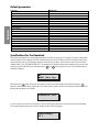
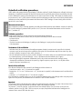
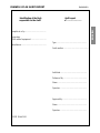
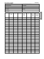
Example of data print by Download (table print)
The following page is a model of printing of the data recorded by a Datalogger and dumped on a disk through the CAREL
Download modules – DLOGSER000. From October 1997 the portable module DLOGPC0000 will be available. Both modules are
managed by Windows™.
In fact each line of the table corresponds to a recording, of which the date, the hour, the temperature measured by the probes, the
state of the digital inputs and of the relay outputs, the information on the Power ON,
on the time change and the alarms are reported.
Furthermore, the data that are included within particular ranges (“fi lters”) selected by the user via software are pointed out in italic
boldface. Thus, it is possible to detect which temperatures have exceeded the high or low temperature thresholds or which are the
data stored by the Datalogger at a certain time interval.
In the model page here reported the following fi lters were selected:
• Selection 1: the data stored between 12:00 and 13:30 hours of the 18/02/1997 day have been sought
• Selection 2: for the probe 1 a high temperature threshold equal to -17.5°C has been selected, equal to the relative threshold
selected in the Datalogger (and so in the Alarm column the corresponding alarm symbol appears).
• Selection 3: for the probe 2 a low temperature threshold equal to -19.0°C, different from the relevant to the threshold selected
in the Datalogger (as a consequence, in the Alarm column no alarm symbol appears).
• Selection 4: the probe 2 has been confi gured only at 9:00 hours of the 18/02/1997 day, and therefore there are temperature
recordings relevant to it only beginning from this hour. In the previous recordings the character “-“ is reported to indicate its
absence.
For a two channel Datalogger model (such as the one presented in the example) the absence of the probes 3 and 4, of the digital
inputs 3 and 4 and of the digital output 2 is similarly reported.
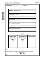
At the end of each page the serial number and model (2N=2 channels, 4N = 4 channels) of the Datalogger, with which the data
have been stored, the name of the operator in charge of the instrument, the signature and date at and hour in which the print has
been carried out are reported.
A space is also provided for the authentication of the document by the fi rm that is the holder of the Datalogger, that may
personalize the print by inserting its own name (“Supermarket “XYZ” in the example) at the head of each page, near the logo and
the writing “Datalogger CAREL”.
Finally it is worth noting that the print is optimized if the interval between two successive recordings is of 15 minutes. In this case
to each page correspond the data being recorded throughout 24 hours.
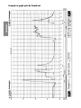
Note: it is possible to print the temperature data graphic on a A4 format sheet. Please fi nd an example of graph print on page 20.
Download OK
Download failure

RIGA DATA ORA Room1 T2 *C T3 *C T4 *C DI1 DI2 DI3 DI4 DO1 DO2 POn
T. c
1 18/02/1997 00:00 -18,0 - - - Off On - - Off - Pon
2 18/02/1997 00:15 -18,0 - - - Off On - - Off -
3 18/02/1997 00:30 -18,0 - - - Off On - - Off -
4 18/02/1997 00:45
-17,5
-17,5 - - - Off On - - Off -
5 18/02/1997 01:00
-17,5
-17,5 - - - Off On - - Off -
6 18/02/1997 01:15
-17,5
-17,5 - - - Off On - - Off -
7 18/02/1997 01:30
-17,5
-17,5 - - - Off On - - Off -
8 18/02/1997 01:45
-17,5
-17,5 - - - Off On - - Off -
9 18/02/1997 02:00
-17,5
-17,5 - - - Off On - - Off -
10 18/02/1997 02:15
-17,5
-17,5 - - - Off On - - Off -
11 18/02/1997 02:30
-17,5
-17,5 - - - Off On - - Off -
12 18/02/1997 02:45
-17,5
-17,5 - - - On On - - Off -
13 18/02/1997 03:00
-17,5
-17,5 - - - On On - - Off -
14 18/02/1997 03:15
-17,5
-17,5 - - - On On - - Off -
15 18/02/1997 03:30
-17,5
-17,5 - - - On On - - Off -
16 18/02/1997 03:45 -18,0 - - - On On - - Off -
17 18/02/1997 04:00 -18,0 - - - On On - - Off -
18 18/02/1997 04:15 -18,0 - - - On On - - Off -
19 18/02/1997 04:30 -18,5 - - - On On - - Off -
20 18/02/1997 04:45 -18,5 - - - On On - - Off -
21 18/02/1997 05:00 -18,5 - - - On On - - Off -
22 18/02/1997 05:15 -19,0 - - - On On - - Off -
23 18/02/1997 05:30 -19,0 - - - Off On - - Off -
24 18/02/1997 05:45 -19,0 - - - Off On - - Off -
25 18/02/1997 06:00 -19,0 - - - Off On - - Off -
26 18/02/1997 06:15 -19,0 - - - Off On - - Off -
27 18/02/1997 06:30 -19,0 - - - Off On - - Off -
28 18/02/1997 06:45 -19,0 - - - Off On - - Off -
29 18/02/1997 07:00 -19,0 - - - Off On - - Off -
30 18/02/1997 07:15 -19,0 - - - Off On - - Off -
31 18/02/1997 07:30 -19,0 - - - Off On - - Off -
32 18/02/1997 07:45 -19,0 - - - Off On - - Off -
33 18/02/1997 08:00 -19,0 - - - Off On - - Off -
34 18/02/1997 08:15 -19,0 - - - Off On - - Off -
35 18/02/1997 08:30 -18,5 - - - Off On - - Off -
36 18/02/1997 08:45 -18,5 - - - Off On - - Off -
37 18/02/1997 09:00 -18,5 -17,5 - - Off On - - Off -
38 18/02/1997 09:15 -18,0 -17,5 - - Off On - - Off -
39 18/02/1997 09:30 -18,0 -17,5 - - Off On - - Off -
40 18/02/1997 09:45 -18,0 -17,5 - - Off On - - Off -
41 18/02/1997 10:00 -18,0 -17,5 - - Off On - - Off -
42 18/02/1997 10:15 -18,0 -17,5 - - Off On - - Off -
43 18/02/1997 10:30 -18,0 -17,5 - - Off On - - Off -
44 18/02/1997 10:45 -18,0 -17,5 - - Off On - - Off -
45 18/02/1997 11:00
-17,5
-17,5 -17,5 - - Off On - - Off -
46 18/02/1997 11:15
-17,5
-17,5 -17,5 - - Off On - - Off -
47 18/02/1997 11:30
-17,5
-17,5 -18,0 - - Off On - - Off -
48 18/02/1997 11:45
-17,5
-17,5 -18,0 - - Off On - - Off -
49 18/02/1997 12:00
-17,5
-17,5 -18,0 - - Off On - - Off -
// -17,5 Off O Off
-17,5
-17,5
-17,5
ENGLISH
Selection 4
Selection 2
Selection 1
Selection 2
SUPERMARKET XYZ

-17,5
-17,5
-17,5
-17,5
-17,5
-17,5
-17,5
-17,5
-17,5
-17,5
-17,5
-17,5
-17,5
-17,5
-17,5
-17,5
-17,5
50 18
/
02
/
1997 12:15
-17,5
-17,5 -18,5 - -
Off O
n--
Off
-
51 18/02/1997 12:30
-17,5
-17,5 -18,5 - - Off On - - Off -
52 18/02/1997 12:45
-17,5
-17,5 -18,5 - - Off On - - Off -
53 18/02/1997 13:00
-17,5
-17,5 -19,0 - - Off On - - Off -
54 18/02/1997 13:15 -18,0 -19,0 - - Off On - - Off -
55 18/02/1997 13:30 -18,0 -19,0 - - Off On - - Off -
56 18/02/1997 13:45 -18,0 -18,5 - - Off On - - Off -
57 18/02/1997 14:00 -18,5 -18,5 - - Off On - - Off -
58 18/02/1997 14:15 -18,5 -18,5 - - Off On - - Off -
59 18/02/1997 14:30 -18,5 -18,5 - - Off On - - Off -
60 18/02/1997 14:45 -19,0 -18,5 - - Off On - - Off -
61 18/02/1997 15:00 -19,0 -18,5 - - Off On - - Off -
62 18/02/1997 15:15 -19,0 -18,5 - - Off On - - Off -
63 18/02/1997 15:30 -19,0 -18,5 - - Off On - - Off -
64 18/02/1997 15:45 -19,0 -18,5 - - Off On - - Off -
65 18/02/1997 16:00 -19,0 -18,5 - - Off On - - Off -
66 18/02/1997 16:15 -19,0 -18,5 - - Off On - - Off -
67 18/02/1997 16:30 -19,0 -18,5 - - Off On - - Off -
68 18/02/1997 16:45 -19,0 -18,5 - - Off On - - Off -
69 18/02/1997 17:00 -19,0 -18,0 - - Off On - - Off -
70 18/02/1997 17:15 -19,0 -18,0 - - Off On - - Off -
71 18/02/1997 17:30 -19,0 -18,0 - - Off On - - Off -
72 18/02/1997 17:45 -19,0 -17,5 - - Off On - - Off -
73 18/02/1997 18:00 -18,5 -17,5 - - Off On - - Off -
74 18/02/1997 18:15 -18,5 -17,5 - - Off On - - Off -
75 18/02/1997 18:30 -18,5 -17,5 - - Off On - - Off -
76 18/02/1997 18:45 -18,0 -17,5 - - Off On - - Off -
77 18/02/1997 19:00 -18,0 -17,5 - - Off On - - Off -
78 18/02/1997 19:15 -18,0 -17,5 - - Off On - - Off -
79 18/02/1997 19:30 -18,0 -17,5 - - Off On - - Off -
80 18/02/1997 19:45 -18,0 -17,5 - - Off On - - Off -
81 18/02/1997 20:00 -18,0 -17,5 - - Off On - - Off -
82 18/02/1997 20:15 -18,0 -17,5 - - Off On - - Off -
83 18/02/1997 20:30 -18,0 -17,5 - - Off On - - Off -
84 18/02/1997 20:45 -18,0 -17,5 - - Off On - - Off -
85 18/02/1997 21:00 -18,0 -18,0 - - Off On - - Off -
86 18/02/1997 21:15 -17,5 -18,0 - - Off On - - Off -
87 18/02/1997 21:30 -17,5 -18,0 - - Off On - - Off -
88 18/02/1997 21:45 -17,5 -18,5 - - Off On - - Off -
89 18/02/1997 22:00 -17,5 -18,5 - - Off On - - Off -
90 18/02/1997 22:15 -17,5 -18,5 - - Off On - - Off -
91 18/02/1997 22:30 -17,5 -18,5 - - Off On - - Off -
92 18/02/1997 22:45 -18,0 -18,5 - - Off On - - Off -
93 18/02/1997 23:00 -18,0 -18,5 - - Off On - - Off -
94 18/02/1997 23:15 -18,0 -18,5 - - Off On - - Off -
95 18/02/1997 23:30 -18,5 -18,5 - - Off On - - Off -
96 18/02/1997 23:45 -18,5 -18,5 - - Off On - - Off -
Data 01/02/1997
Ora 15:30
Firma .................................
N. Serie : 104
Modello : 2N
Nome operatore : ...........................
Timbro
Ora 15:30
Firma .......................
Pag. 1
ENGLISH
Selection
1
Selection 3

ENGLISH
Example of graph print by Download
La pagina sta caricando ...
La pagina sta caricando ...
La pagina sta caricando ...
La pagina sta caricando ...
La pagina sta caricando ...
La pagina sta caricando ...
La pagina sta caricando ...
La pagina sta caricando ...
-
 1
1
-
 2
2
-
 3
3
-
 4
4
-
 5
5
-
 6
6
-
 7
7
-
 8
8
-
 9
9
-
 10
10
-
 11
11
-
 12
12
-
 13
13
-
 14
14
-
 15
15
-
 16
16
-
 17
17
-
 18
18
-
 19
19
-
 20
20
-
 21
21
-
 22
22
-
 23
23
-
 24
24
-
 25
25
-
 26
26
-
 27
27
-
 28
28


Carel Datalogger Manuale utente
- Categoria
- Misurazione, test
- Tipo
- Manuale utente
in altre lingue
- English: Carel Datalogger User manual
Documenti correlati
-
Carel mchiller compact Manuale utente
-
Carel heaterSteam Manuale utente
-
-
Carel PJ easy XL Manuale utente
-
-
-
-
-