Shindaiwa SBA-P24 Manuale utente
- Categoria
- Motoseghe
- Tipo
- Manuale utente

1????
OPERATOR'S MANUAL
MANUEL D'UTILISATION
BEDIENUNGSANLEITUNG
MANUALE PER L'OPERATORE
SBA-P24
ENGLISH
FRANÇAIS
DEUTSCH
ITALIANO
WARNING
READ THE INSTRUCTIONS CAREFULLY AND FOLLOW THE RULES FOR
SAFE OPERATION.
FAILURE TO DO SO COULD RESULT IN SERIOUS INJURY.
AVERTISSEMENT
LIRE ATTENTIVEMENT LES INSTRUCTIONS ET SUIVRE LESRÈGLES DE
SECURITÉ.LE NON-RESPECT DES RÈGLES DE SÉCURITÉ ENTRAÎNE UN
RISQUE DE BLESSURE GRAVE.
WARNUNG
LESEN SIE DIE BEDIENUNGSANLEITUNG SORGFÄLTIG DURCH, UND
BEFOLGEN SIE DIE SICHERHEITSREGELN. ANDERNFALLS BESTEHT DAS
RISIKO SCHWERER VERLETZUNGEN.
AVVERTENZA
LEGGERE E SEGUIRE ATTENTAMENTE LE ISTRUZIONI PER LAVORARE IN
CONDIZIONI DI MASSIMA SICUREZZA. LA MANCATA OSSERVANZA DELLE
ISTRUZIONI POTREBBE PROVOCARE LESIONI GRAVI.


1Cover
ENGLISH
(Original instructions)
OPERATOR'S MANUAL
SPLITBOOM ATTACHMENT
SBA-P24
WARNING
READ THE INSTRUCTIONS CAREFULLY AND FOLLOW THE
RULES FOR SAFE OPERATION.
FAILURE TO DO SO COULD RESULT IN SERIOUS INJURY.

2
Important information
2Important informati on
Please ensure that you read the operator's manual before using your product.
Intended use of this product
This product is designed and built to deliver superior performance and reliability without compromise to quality, comfort,
safety or durability. As an owner/operator, you'll soon discover for yourself why shindaiwa is simply in a class by itself!
Do not use this unit for any purpose other than aforementioned.
Users of the product
You should not use this product until you have read the operator's manual carefully and fully absorbed its content.
This product should not be used by anyone who has failed to read the operator's manual properly, is suffering from a
cold, tiredness or otherwise in poor physical condition, or children.
Keep in mind that the operator or user is responsible for accidents or hazards occurring to other people or their prop-
erty.
About your operator's manual
This manual contains necessary information about the assembly, operation, and maintenance of your product. Please
read it carefully and absorb its contents.
Always keep your manual in a place where it is readily accessible.
If you have lost your manual or it is damaged and no longer readable, please purchase a new one from your shindaiwa
dealer.
The units used in this manual are SI units (International System of Units). Figures in parentheses are reference values,
and there may be a slight conversion error in some cases.
Loaning or assigning your product
When loaning the product described in this manual to another party, ensure that the person borrowing and working with
the product receives the operator's manual along with the product. If you assign your product to another party, please
enclose the operator's manual with the product when handing it over.
Enquiries
Please contact your shindaiwa dealer for requests regarding information about your product, the purchase of consum-
ables, repairs, and other such enquiries.
Notices
The content of this manual may be changed without notice for the purpose of upgrades to the product. Some of the
illustrations used may differ from the product itself in order to make the explanations clearer.
This product requires the assembly of some parts.
Please consult your shindaiwa dealer if anything is unclear or of concern.
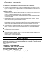
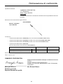
Manufacturer:
YAMABIKO CORPORATION
1-7-2 Suehirocho, Ohme, Tokyo 198-8760, JAPAN
Authorized Representative in Europe:
CERTIFICATION EXPERTS B.V.
P.O. box 5047, Merwedeweg 2, 3621 LR Breukelen, The Netherlands
WARNING
This product is specifically designed for use with a shindaiwa Multipurpose Engine. Installation and/or use on any other
model, brand, or type of power tool is not approved by shindaiwa. Attempts to use on non-approved models can dam-
age the equipment and cause accidents, serious injury, or death. Never permit a person without training or instruction
to operate this unit.

3
Contents
For safe use of your product............................................................................................... 4
Warning notices............................................................................................................. 4
Other indicators ............................................................................................................. 4
Symbols.........................................................................................................................4
Location in which a safety decal is attached.................................................................. 5
Handling the product ..................................................................................................... 6
Description........................................................................................................................ 10
Before you start ................................................................................................................11
Assembly ..................................................................................................................... 11
Adjusting the balance .................................................................................................. 14
Operation .......................................................................................................................... 15
Maintenance .....................................................................................................................17
Daily Maintenance ....................................................................................................... 17
10/15 Hour Maintenance ............................................................................................. 17
50-Hour Maintenance .................................................................................................. 17
Long term storage ....................................................................................................... 17
Saw chain maintenance............................................................................................... 18
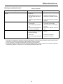
Troubleshooting Guide ................................................................................................ 20
Specifications.................................................................................................................... 21
Declaration of conformity .................................................................................................. 22

4
For safe use of your product
For safe use of yo ur product
Be careful to read this section before using your product.
The precautions described in this section contain important safety information. Please observe them carefully.
You must also read the precautions that appear in the body of the manual itself.
Text following a [diamond mark] mark describes the potential consequences of failing to observe the precaution.
Warning notices
Situations where there is a risk of physical injury to the operator and other people are indicated in this manual and on the product
itself by the following warning notices. Always read and observe them carefully in order to ensure safe operation.
Other indicators
As well as warning notices, this manual uses the following explanatory symbols:
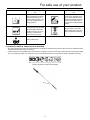
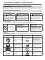
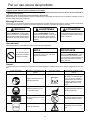
Symbols
In this manual and on the product itself, a series of explanatory symbols is used. Please make sure that you fully understand what
each symbol means.
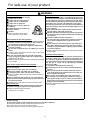
DANGER WARNING CAUTION
This symbol accompanied by the
word "DANGER" calls attentions to
an act or a condition which will lead to
serious personal injury or death of op-
erators and bystanders.
This symbol accompanied by the
word "WARNING" calls attentions to
an act or a condition which can lead to
serious personal injury or death of op-
erators and bystanders.
"CAUTION" indicates a potentially
hazardous situation which, if not
avoided, may result in minor or mod-
erate injury.
Circle and slash sym-
bol means whatever is
shown is prohibited.
NOTE IMPORTANT
This enclosed message provides tips
for use, care and maintenance of the
product.
Framed text featuring the word "IM-
PORTANT" contains important infor-
mation about the use, checking,
maintenance and storage of the prod-
uct described in this manual.
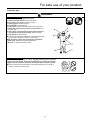
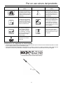
Symbol form/shape Symbol description/applica-
tion
Symbol form/shape Symbol description/applica-
tion
Carefully read the operator's
manual
Keep bystanders at least 15
meters away from the operat-
ing product to reduce the risk
of being struck by falling ob-
jects or thrown debris.
Wear eyes, ears and head
protection
Beware of high-temperature
areas
Wear foot protection and
gloves
Be aware of the danger of fall-
ing debris.
Emergency stop Beware of electric shocks
Never operate product if you
are tired or are under the influ-
ence of alcohol, drugs, medi-
cation or any other substance
that could affect your ability or
judgement.
This product conducts elec-
tricity. Keep the product and/
or operator a minimum dis-
tance of 10 meters away from
electrical source and power
lines.

5
For safe use of your product
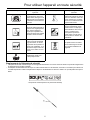
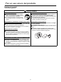
Location in which a safety decal is attached
The safety decal shown below has been attached to the products described in this manual. Ensure that you understand what
the decal means before using your product.
If the decal becomes unreadable due to wear and tear or damage, or peels off and is lost, please purchase a replacement decal
from your dealer and attach it in the location shown in the illustrations below. Ensure that the decal is readable at all times.
Never operate the product at
an angle greater than 60° in
order to reduce the risk of be-
ing struck by falling objects
during operation.
Kickback can occur whenever
the tip of the guide bar touch-
es an object while the saw is
operating. Kickback may force
the bar up and back toward
the operator with lightning-like
speed!
Pinching the saw along the tip
of the guide bar may force the
bar back rapidly toward the
operator.Pinching can occur
whenever wood closes in
around the moving chain.
Never touch the saw chain
when starting the engine and
while operating this maching.
Chain of fill/oil pump
Symbol form/shape Symbol description/applica-
tion
Symbol form/shape Symbol description/applica-
tion
1. Safety decal (Part number X505-003420)

6
For safe use of your product
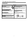
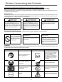
Handling the product
General precautions
WARNING
Operator's manual
Be careful to read the operator's manual
properly before using your product in or-
der to ensure correct operation.
Failure to do so could lead to an accident or
serious injury.
Do not use the product for anything
other than its intended purpose
You must not use the product for any purpose other
than those described in the operator's manual.
To do so could lead to an accident or serious injury.
Do not modify the product
You must not modify the product.
To do so could lead to an accident or serious injury. Any
malfunction resulting from a modification to the product will
not be covered by the manufacturer's warranty.
Do not use the product unless it has been checked
and maintained
You must not use the product unless it has been
checked and maintained. Always ensure that the prod-
uct is checked and maintained on a regular basis.
Failure to do so could lead to an accident or serious injury.
Loaning or assigning your product
When loaning your product to another party, ensure
that the person borrowing the product receives the op-
erator's manual along with it.
If you assign your product to another party, please en-
close the operator's manual with the product when
handing it over.
Failure to do so could lead to an accident or serious injury.
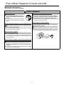
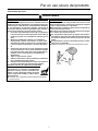
Being prepared in case of an injury
In the unlikely event of an accident or injury, please ensure
that you are prepared.
First aid kit
Towels and wipes (to stop any bleeding)
Whistle or mobile phone (for calling outside help)
If you are unable to perform first aid or call for outside help,
the injury could worsen.

7
For safe use of your product
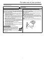
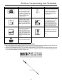
Precautions for use
WARNING
Kickback and Pinching Safety Precautions
Both kickback and pinching may cause you to lose control
of the product which could result in serious personal inju-
ry. Do not rely exclusively on the safety device built into
the product. You must take several steps to keep your jobs
free from accident or injury:
1. Understand kickback and pinching! You can reduce or
eliminate the element of surprise. Sudden surprises
contributes to accidents.
2. Keep a firm grip on the product with both hands when-
ever the engine is running. A firm grip will help you re-
duce the effects of kickback and pinching as well as
maintain control of the machine.
3. Make sure the area in which you are cutting is free
from obstructions. Do not let the nose of the guide bar
contact a log, branch, or any other obstructions which
could be hit while you operate the product.
4. Cut at high engine speeds.
5. Follow the manufacturer's instructions for sharpening
and maintaining the chain.
6. Use only the replacement bar and chain or equivalent
as specified by the manufacturer.
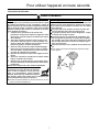
Avoid hot surfaces
During operation, the complete unit, especial-
ly the drive shaft housing, power head, muf-
fler area and gear box may become very hot,
too hot to touch. Avoid contact during and im-
mediately after operation.
You could burn yourself if you touch a high temperature
component.
The area within a 15 m radius is a danger zone
The area within a 15 m radius of the product is a danger
zone. Be careful to observe the following precautions
while working with the product.
Do not allow children and other people or pets to enter
the danger zone.
If another person enters the danger zone, turn off the
engine to stop the saw chain.
When approaching the operator, signal to him by, for
example, throwing twigs from outside the danger zone,
and then check that engine has been switched off and
the blade has stopped moving.
Do not allow anyone to hold the material you are cut-
ting.
Any contact with the cutter blade could cause serious injury.

8
For safe use of your product
WARNING
Users of the product
The product should not be used by:
people who are tired
people who have taken alcohol
people who are on medication
people who are pregnant
people who are in poor physical
condition
people who have not read the op-
erator's manual
children
Failure to observe these instruc-
tions could lead to an accident.
Environment of use and operation
Do not use the product in places where there is no sure
foothold, such as on steep slopes or after rainfall, as
such places are slippery and dangerous.
Do not operate the product at night or in dark places
with poor visibility.
Do not work in odd positions or on ladders. Do not over
reach.
A serious injury could result if you fall or slip, or fail to oper-
ate the product correctly.
For your own health and your safe and comfortable
work, operate the machine within the air temperature
range of -5
o
C to 40
o
C.
Failure to observe these instructions could result in damage
to your health.
Turn off the engine when moving around
When moving around in the situations described below,
turn off the engine.
Moving to the place where you are working
Moving to another area while you are working
Leaving the place where you have been working
Failure to observe these precautions could cause burns or
serious injury.
When transporting the product by car, empty the fuel
tank, and secure the product firmly in place to prevent it
from moving around.
Travelling by car with fuel in the tank could lead to a fire.
Keep a firm grip
Hold the front and rear handles with both hands with
thumbs and fingers tightly encircling the handles.
Failure to observe these instructions
could lead to an accident.
Vibration and cold
It is believed that a condition called Raynaud's Phenome-
non which affects the fingers of certain individuals may be
brought about by exposure to vibration and cold. Expo-
sure to vibration and cold may cause tingling and burning,
followed by loss of colour and numbness in the fingers.
The following precautions are strongly recommended be-
cause the minimum exposure which might trigger the ail-
ment is unknown.
Keep your body warm, especially the head and neck,
feet and ankles, and hands and wrists.
Maintain good blood circulation by performing vigorous
arm exercises during frequent work breaks, and also by
not smoking.
Limit the number of hours of operation.
Try to fill each day with jobs where operating the trim-
mer or other hand-held power equipment is not re-
quired.
If you experience discomfort redness and swelling of
the fingers, followed by whitening and loss of feeling,
consult your physician before exposing yourself further
to cold and vibration.
Failure to observe these instructions could result in damage
to your health.
Repetitive stress injuries
It is believed that over-using the muscles and tendons of
the fingers, hands, arms and shoulders may cause sore-
ness, swelling, numbness, weakness and extreme pain to
the areas just mentioned. Certain repetitive hand activities
may put you at a high risk for developing a repetitive
stress injury (RSI).
To reduce the risk of RSI, do the following:
Avoid using your wrist in a bent, extended or twisted
position.
Take periodic breaks to minimize repetition and rest
your hands. Reduce the speed and force in which you
do the repetitive movement.
Do exercises to strengthen hand and arm muscles.
See a doctor if you feel tingling, numbness or pain in
your fingers, hands, wrists or arms. The sooner RSI is
diagnosed, the more likely permanent nerve and muscle
damage can be prevented.
Failure to observe these instructions could result in damage
to your health.
Proper training
Do not permit operation without proper training and protective equipment.
Be thoroughly familiar with the controls and proper use of unit.
Know how to stop the unit and shut off the engine.
Never allow anyone to use the unit without proper instruction.

9
For safe use of your product
Protective gear
WARNING
Wear protective gear
Always wear the following protective gear.
a Head protection (helmet): Protects the head
b Ear muffs or ear plugs: Protect the hearing
c Safety goggles: Protect the eyes
d Face shield: Protects the face
e Safety gloves: Protect the hands from cold and vibration
f Work clothes that fit (long sleeves, long trousers): Pro-
tect the body
g Heavy duty, non-slip protective boots (with toecaps) or
non-slip work shoes (with toecaps): Protect the feet
h Shin guards: Protect the legs
Failure to observe these precautions could result in damage
to your sight or hearing, or lead to a serious injury.
When necessary, please use the protective gear below.
Dust mask: Protects the breathing apparatus
Bee net: To deal with attacks by bees
Wear proper clothing.
Do not wear ties, jewellery, or loose, dangling clothing which could be
caught in the unit. Do not wear open toed footwear, or go bare-foot or barel-
egged. In certain situations, total face and head protection may be required.
Failure to observe these precautions could result in damage to your sight or
hearing, or lead to a serious injury.

10
Description
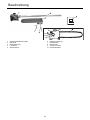
Description
1. Gearcase/Cutting head
2. Outer tube
3. Cover
4. L-wrench
5. Socket wrench
6. Operator's manual
7. Gearcase
8. Oil Filler cap
9. Guide bar and chain
10. Bar oil reservoir

11
Before you start
Before you start
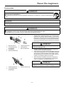
Assembly
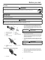
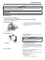
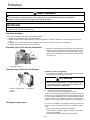
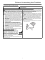
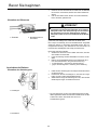
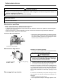
Installing a Tool Attachment
1. Place Multipurpose Engine and the Splitboom Attachment
on a clean, flat surface so that both assemblies fit end to
end. The powerhead assembly should be facing up, and the
Splitboom Attachment should be positioned with the locking
hole in the tube end facing up.
2. Slip off the protective cover from the end of the tool, and
loosen the coupler screw knob.
3. Insert the tube into the coupler, with the tool decal facing up,
until the line of the decal is flush with the end of the coupler.
Twist the tool back and forth until you are sure it snaps in
place by the coupler latch.
4. When the two tube halves are locked together, press down
on the spring-loaded latch protector and tighten the coupler
screw.
Disassembling the Tool Attachment
1. Place the unit on a clean, flat surface, loosen the coupler
screw. The spring loaded coupler protector should pop up.
2. Press down on the latch with your finger or thumb. This re-
leases the coupler lock.
3. Pull the tube out of the coupler.
WARNING
Read the operator's manual carefully to ensure that you assemble the product correctly.
Using a product that has been incorrectly assembled could lead to an accident or serious injury.
IMPORTANT
The terms "left", "left-hand", and "LH"; "right", "right-hand", and "RH"; "front" and "rear" refer to directions as viewed by the op-
erator during normal operation.
WARNING
Never attempt to install, replace, or adjust the chain while the engine is running.
The saw chain is very sharp. Wear gloves to protect your hands when handling.
Failure to do so could lead to an injury or serious accident, or cause a fire.
1. Multipurpose engine
2. Latch protector (ex-
tended)
3. Latch
4. Coupler screw knob
5. Coupler
6. Locking hole
7. Splitboom attachment
CAUTION
Keep the open ends of the tubes clean and free of debris.
1. Coupler
2. Latch protector (low-
ered)
3. Coupler screw knob
CAUTION
Make sure there is no gap between the Latch protector and
the coupler.
1. Press latch

12
Before you start
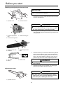
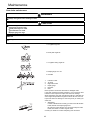
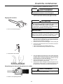
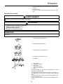
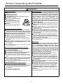
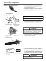
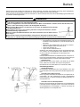
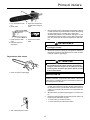
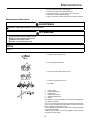
Installing and adjusting the bar and chain
1. Using the small end of the socket wrench, remove the
sprocket covernut (turn counterclockwise to remove) and re-
move the sprocket cover.
2. Place the guide bar over the guide bar adjustment stud on the
cutting assembly. Align the chain tensioning pin with the hole
in the guide bar.
3. Install the chain loop over the drive links within the guide bar
groove, and then align the chain over the drive sprocket.
Make sure the cutters are properly oriented as shown in this
figure. If the chain installation is difficult or if the chain ap-
pears too tight, refer to the section "Adjusting the Chain".
4. Install the sprocket cover over the bar stud. Using finger-
pressure only, install the sprocket cover nut.
Adjusting the chain
1. Sprocket cover 2. Sprocket cover nut
IMPORTANT
For the longest chain life, let new or replacement chain loops
soak in oil overnight before installation.
1. Guide bar adjustment
stud
2. Chain tensioning screw
3. Chain tensioning pin
CAUTION
Failure to align the guide bar and chain tensioning pin
can cause serious damage to the sprocket cover, guide
bar, chain tensioning pin, and cutting assembly.
1. Chain tensioner hole
2. Guide bar
3. Guide bar adjustment
stud
1. Top of Bar
2. Bar tip
3. Bottom of bar
WARNING
Never operate the pole pruner tool without the sprocket
cover installed.
1. Sprocket cover nut
CAUTION
A loose chain can jump off the guide bar causing dam-
age to the chain and associated equipment. Always
make sure the chain is properly adjusted; check more
often when you are breaking in a new chain.

13
Before you start
1. Place Splitboom Attachment on a clean, flat surface. (For re-
adjustment during operation, shut down the engine, then al-
low the guide bar and chain to cool before proceeding with
the adjustment procedure.)
2. Loosen the sprocket cover nut with the socket wrench.
3. Lift the nose of the guide bar while turning the chain tension-
ing screw.
clockwise to tighten the chain.
anticlockwise to loosen the chain.
4. Pull the chain by hand along the top of the guide bar several
times from the engine to the bar's tip. The chain should feel
snug but still pull freely.
5. Tighten the sprocket cover nut securely while lifting the tip of
the guide bar.
6. Inspect the chain for the correct adjustment (more frequently
with a new chain). The chain should feel snug but still pull
freely.
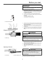
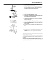
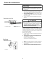
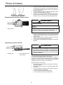
Filling the chain oiler reservoir
1. Place Splitboom Attachment on a clean, flat surface with the
oil filler cap facing up. Wipe off any debris from the oil cap
and from around the oil filler neck.
2. Remove the oil filler cap and fill the reservoir with bar and
chain oil, then replace the cap.
3. Wipe up any spilled oil from the unit before restarting the
product.
Adjusting oil flow rate
The guide bar and chain are lubricated automatically by a pump
that operates whenever the chain rotates.
IMPORTANT
Proper chain adjustment is essential for maximum perfor-
mance, long chain life, and operator safety. Always inspect
chain tension before operating product.
1. Chain tensioning screw
1. Oil filler cap
WARNING
Never fill the oil reservoir or adjust the oiler with the en-
gine running.
NOTE
The oil reservoir has a capacity sufficient to provide about 40
minutes of cutting time (when set to deliver the minimum flow
rate, or about as long as you'll get from a tank of fuel).
1. Oil reservoir 2. Oil flow adjusting screw
CAUTION
An increase in bar oil flow rate will speed oil consump-
tion, requiring more frequent checks on the oil reser-
voir. To ensure sufficient lubrication, It may be
necessary to check the oil level more frequently than at
fuel tank refills.

14
Before you start
The pump is set at the factory to deliver a minimum flow rate, but
it can be adjusted in the field. A temporary increase in oil flow is
often desirable when cutting things like hardwood or wood with a
lot of pitch.
Adjust the pump as follows:
1. Stop the engine and make sure the stop switch is in the OFF
position.
2. Place the product on its side with the oil reservoir up.
3. Using a screwdriver, turn the oil flow rate adjustment screw
in the desired direction:
clockwise–decrease lubrication.
anticlockwise–increase lubrication.
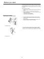
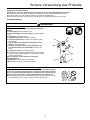
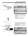
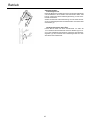
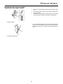
Adjusting the balance
Adjusting the shoulder harness
1. Hook the harness hook to the hanger on the outer tube.
2. Wear the shoulder harness so that the hook stays at your
right hand side.
3. Adjust the length of the shoulder harness so that you can
hold and operate the machine comfortably.
The shoulder harness is fitted with an emergency release
function. In case of emergency, strongly pull the emergency
tab at the hook. The machine will be released from the strap.
1. Shoulder harness
1. Emergency tab

15
Operation
Operation
Preparations
Check unit for loose/missing nuts, bolts and screws. Tight-
en and/or replace as needed.
Choose the best work position for safety against the falling
object (Branch etc)
Start the engine.
Put on the strap.
Never stand underneath the branch you are cutting–be wary of
falling branches. Note that a branch may spring back at you after
it hits the ground.
Cutting Sequence
To allow branches a free fall always cut the lower branches first.
Prune heavy branches (large diameter) in several controllable
pieces.
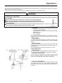
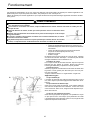
Working Position
Hold the control handle with your right hand, and the shaft with
your left hand. Your left arm should be extended to the most com-
fortable position.
The shaft should always be held at an angle of 60° or less.
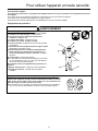
Typical applications
Standard cut(A):
The most convenient working position is a tool angel of 60°, but
any other angle may be used to suit the situation concerned.
Cutting above obstacles(B):
Thanks to the unit's long reach it is possible to prune branches
that are overhanging obstacles, such as rivers or lakes. The tool
angle in this case depends on the position of the branch.
Cutting on a work platform:
The unit's long reach enables cutting to be performed next to the
trunk without the risk of the work platform damaging other
branches. The tool angle in this case depends on the position of
the branch.
This product is designed especially for cutting branches. Never use this product for any other purposes. Never try to cut stones,
metals, plastics or any other hard objects.
Using for other purposes than cutting branches may damage the machine or cause serious injury.
WARNING
Stop the product immediately if it suddenly begins to vibrate or shake. Inspect for broken, missing or improperly
installed parts or attachments.
If a saw blade should bind fast in a cut, shut off the engine immediately. Push the branch or tree to ease the bind and
free the blade.
Before starting the engine, make sure the saw chain is not contacting anything.
Make sure the chain cover is in place when transporting and storing the pruner.
When carrying the Multipurpose Engine with the pole pruner tool, the chain should be
pointing backward.
Never transport the pruner or set it down with the engine running. An engine that's run-
ning could be accidently accelerated causing the chain to rotate.

16
Operation
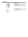
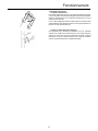
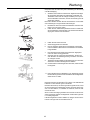
Working techniques
Relieving cut:
To avoid tearing the bark, kickback or pinching the bar when
pruning thick branches, always start by performing a relieving cut
(1) on the underside of the branch.
To do this, apply the cutting attachment and pull it across the bot-
tom of the branch as far as the bar nose. Perform the cross-cut
(2).
Flush-cutting thick branches:
If branch diameter is more than 10cm, first perform undercut (3)
and cross-cut at a distance (A) of about 25cm from the final cut.
Then carry out the flush-cut (4), starting with a relieving cut and
finishing with a cross-cut.

17
Maintenance
Maintenance
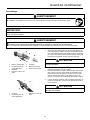
Daily Maintenance
10/15 Hour Maintenance
Remove the sprocket cover and inspect the sprocket for ex-
cessive dirt, debris, or wear. Remove the guide bar and clean
out the guide bar groove. If the sprocket is excessively worn,
replace it with a new one.
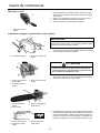
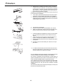
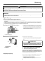
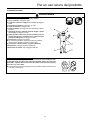
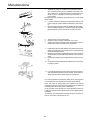
50-Hour Maintenance
Lubricate the gearcase
To perform this operation, first remove the gearcase from the
outer tube as follows:
1. Loosen the gearcase clamp bolt.
2. Remove the index bolt from the gearcase.
3. Slide the gearcase out of the tube.
Using a lever-type grease gun, pump lithium-base grease (about
10 grams) into the grease fitting until you see old grease being
purged from the gearcase, which can be seen in the outer tube
cavity. Clean up excess grease, then reassemble the gearcase
onto the outer tube.
Long term storage
Whenever the unit will not be used for 30 days or longer, use the
following procedures to prepare it for storage.
Clean external parts thoroughly.
Before storing the unit, repair or replace any worn or damaged
parts.
Drain bar oil from oil tank.
Store the unit in a clean, dust-free area.
Lubricate gearcase.
Cover the chain and the guide bar with the cover.
WARNING
Before performing any maintenance, repair, or cleaning work on the unit, make sure the engine and cutting attach-
ment are completely stopped. Disconnect the spark plug wire before performing service or maintenance work.
Always wear gloves when working around the saw chain.
IMPORTANT
Time intervals are maximum. Actual use and your experience will determine the frequency of required maintenance.
Prior to each work day, perform the following:
Clean any debris or dirt from the cutting attachment.
Lubricate the cutters before use and after refueling. Check the cutters for damage or incorrect adjustment.
Check for loose or missing screws or components. Make sure the cutting attachment is securely fastened.
Make sure nuts, bolts, and screws are tight.
1. Inspect the sprocket
1. Gearcase clamp
2. Index bolt
3. Grease fitting
CAUTION
Do not remove the D-shaped shim washer from the
gearcase clamp. The shim washer prevents damage
from overtightening the tube clamp bolt.

18
Maintenance
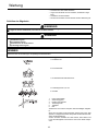
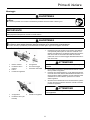
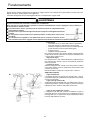
Saw chain maintenance
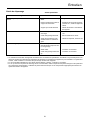
Properly filed cutters are shown below.
A: Top plate angle 30°
B: Side plate angle 80°
C: Top plate cutting angle 50°
D: Depth gauge 0.51 mm
E: Parallel
1. Left hand cutter
2. Tie strap
3. Right hand cutter
4. Depth gauge
5. Drive link
6. Rivet
Never operate a chain saw with a dull or damaged chain.
If the chain requires excessive pressure to cut or produces dust
instead of wood chips then inspect the cutters for damage.
When sharpening the chain the objective will be to maintain the
same angles and profiles throughout its life as when it was new.
Inspect the chain for damage or wear every time you refuel your
chain saw.
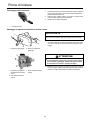
1. Sharpening
In order to file the chain correctly you need: round file and file
holder, flat file and a depth gauge tool.
By using the correct file size (4.5 mm Round file) and a file
holder, it is easier to receive a good result.
Consult your dealer for correct sharpening tools and sizes.
WARNING
Switch off the engine before sharpening the chain.
Always wear gloves when working on chain.
CAUTION
The following faults will increase the risk of kickback considerably.
1)Top plate angle too large
2)Side plate angle too small
3)File diameter too small
4)Depth gauge too large
NOTE
These angles are referred to as Oregon 90SG saw chain. For other branded saw chain, follow it's chain manufacturer's instruc-
tion.
La pagina si sta caricando...
La pagina si sta caricando...
La pagina si sta caricando...
La pagina si sta caricando...
La pagina si sta caricando...
La pagina si sta caricando...
La pagina si sta caricando...
La pagina si sta caricando...
La pagina si sta caricando...
La pagina si sta caricando...
La pagina si sta caricando...
La pagina si sta caricando...
La pagina si sta caricando...
La pagina si sta caricando...
La pagina si sta caricando...
La pagina si sta caricando...
La pagina si sta caricando...
La pagina si sta caricando...
La pagina si sta caricando...
La pagina si sta caricando...
La pagina si sta caricando...
La pagina si sta caricando...
La pagina si sta caricando...
La pagina si sta caricando...
La pagina si sta caricando...
La pagina si sta caricando...
La pagina si sta caricando...
La pagina si sta caricando...
La pagina si sta caricando...
La pagina si sta caricando...
La pagina si sta caricando...
La pagina si sta caricando...
La pagina si sta caricando...
La pagina si sta caricando...
La pagina si sta caricando...
La pagina si sta caricando...
La pagina si sta caricando...
La pagina si sta caricando...
La pagina si sta caricando...
La pagina si sta caricando...
La pagina si sta caricando...
La pagina si sta caricando...
La pagina si sta caricando...
La pagina si sta caricando...
La pagina si sta caricando...
La pagina si sta caricando...
La pagina si sta caricando...
La pagina si sta caricando...
La pagina si sta caricando...
La pagina si sta caricando...
La pagina si sta caricando...
La pagina si sta caricando...
La pagina si sta caricando...
La pagina si sta caricando...
La pagina si sta caricando...
La pagina si sta caricando...
La pagina si sta caricando...
La pagina si sta caricando...
La pagina si sta caricando...
La pagina si sta caricando...
La pagina si sta caricando...
La pagina si sta caricando...
La pagina si sta caricando...
La pagina si sta caricando...
La pagina si sta caricando...
La pagina si sta caricando...
La pagina si sta caricando...
La pagina si sta caricando...
La pagina si sta caricando...
La pagina si sta caricando...
La pagina si sta caricando...
La pagina si sta caricando...
La pagina si sta caricando...
La pagina si sta caricando...
La pagina si sta caricando...
La pagina si sta caricando...
La pagina si sta caricando...
La pagina si sta caricando...
La pagina si sta caricando...
La pagina si sta caricando...
-
 1
1
-
 2
2
-
 3
3
-
 4
4
-
 5
5
-
 6
6
-
 7
7
-
 8
8
-
 9
9
-
 10
10
-
 11
11
-
 12
12
-
 13
13
-
 14
14
-
 15
15
-
 16
16
-
 17
17
-
 18
18
-
 19
19
-
 20
20
-
 21
21
-
 22
22
-
 23
23
-
 24
24
-
 25
25
-
 26
26
-
 27
27
-
 28
28
-
 29
29
-
 30
30
-
 31
31
-
 32
32
-
 33
33
-
 34
34
-
 35
35
-
 36
36
-
 37
37
-
 38
38
-
 39
39
-
 40
40
-
 41
41
-
 42
42
-
 43
43
-
 44
44
-
 45
45
-
 46
46
-
 47
47
-
 48
48
-
 49
49
-
 50
50
-
 51
51
-
 52
52
-
 53
53
-
 54
54
-
 55
55
-
 56
56
-
 57
57
-
 58
58
-
 59
59
-
 60
60
-
 61
61
-
 62
62
-
 63
63
-
 64
64
-
 65
65
-
 66
66
-
 67
67
-
 68
68
-
 69
69
-
 70
70
-
 71
71
-
 72
72
-
 73
73
-
 74
74
-
 75
75
-
 76
76
-
 77
77
-
 78
78
-
 79
79
-
 80
80
-
 81
81
-
 82
82
-
 83
83
-
 84
84
-
 85
85
-
 86
86
-
 87
87
-
 88
88
-
 89
89
-
 90
90
-
 91
91
-
 92
92
-
 93
93
-
 94
94
-
 95
95
-
 96
96
-
 97
97
-
 98
98
-
 99
99
-
 100
100


Shindaiwa SBA-P24 Manuale utente
- Categoria
- Motoseghe
- Tipo
- Manuale utente
in altre lingue
- English: Shindaiwa SBA-P24 User manual
- français: Shindaiwa SBA-P24 Manuel utilisateur
- Deutsch: Shindaiwa SBA-P24 Benutzerhandbuch
Documenti correlati
-
Shindaiwa MTA-PP/E Manuale utente
-
-
-
-
-
-
-
-
-
Shindaiwa 251TS Manuale utente