
www.furuno.com
A
ll brand and product names are trademarks, registered trademarks or service marks of their respective holders.
Installation Manual
RADAR SENSOR
Model
(Product Name: SOLID STATE DOPPLER RADAR)
SAFETY INSTRUCTIONS ................................................................................................ i
SYSTEM CONFIGURATION .......................................................................................... iii
EQUIPMENT LISTS........................................................................................................ iv
FOREWORD.................................................................................................................... v
1. INSTALLATION.......................................................................................................... 1
1.1 Installation Considerations....................................................................................................1
1.2 Installation of the Radar Sensor............................................................................................3
1.3 Wiring....................................................................................................................................7
2. INITIAL SETUP........................................................................................................... 8
2.1 Check Points After Installation ..............................................................................................8
2.2 Initial Setup ...........................................................................................................................8
3. MAINTENANCE, TROUBLE- SHOOTING............................................................... 15
3.1 Maintenance .......................................................................................................................15
3.2 Replacement of Fuse..........................................................................................................15
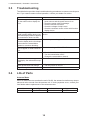
3.3 Troubleshooting ..................................................................................................................16
3.4 Life of Parts.........................................................................................................................16
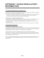
APPENDIX 1 RADIO REGULATORY INFORMATION ............................................AP-1
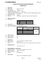
SPECIFICATIONS ..................................................................................................... SP-1
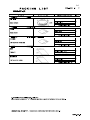
PACKING LISTS ......................................................................................................... A-1
OUTLINE DRAWING................................................................................................... D-1
INTERCONNECTION DIAGRAM ................................................................................ S-1

i
SAFETY INSTRUCTIONS
The installer of the equipment must read the safety instructions before attempting to
install the equipment.
Warning, Caution Prohibitive Action Mandatory Action
Wear a safety belt and hard
hat when working on the
antenna unit.
Serious injury or death can
result if someone falls from the
radar mast.
ELECTRICAL SHOCK HAZARD
Do not open the equipment.
The installation does not require
you to open the radar sensor.
Be sure the power source is
compatible with the voltage
rating of the equipment.
Connection of an incorrect
power source can cause fire or
damage the equipment.
Turn off the power at the power
source before beginning the
installation.
Fire, electrical shock or serious
injury can result if the power is left
on or is applied while the
equipment is being installed.
Do not disassemble or modify
the equipment.
Fire, electrical shock or serious
injury can result.
Use the proper fuse.
Use of a wrong fuse can damage
the equipment or cause fire.
Do not depend one navigation
device for the navigation of the
vessel.
For the safety of vessel and crew,
the navigator must check all aids
available to confirm position.
Indicates a potentially hazardous situation which, if not avoided,
could result in death or serious injury.
WARNING
Indicates a potentially hazardous situation which, if not avoided,
can result in minor or moderate injury.
CAUTION
WARNING WARNING

SAFETY INSTRUCTIONS
ii
It is recommended that you
connect the sensor to a
disconnecting device (circuit
breaker, etc.) to control the
power.
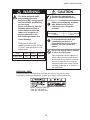
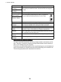
Observe the following compass
safe distances to prevent
interference to a magnetic
compass.
Standard compass
Steering compass
0.55 m 0.30 m
The radar antenna emits
electromagnetic radio
frequency (RF) energy which
can be harmful, particularly
to your eyes.
Never look directly into the
antenna aperture from a
close distance while the
radar is in operation or
expose yourself to the
transmitting antenna at a
close distance.
Distances at which RF
radiation levels of 100, 50 and
10 W/m
2
exist are given in the
table below.
100W/m
2
10W/m
2
Model
DRS4D-NXT N/A 0.7 m
50W/m
2
N/A
CAUTION
Ground the equipment to
prevent mutual interference.
WARNING LABEL
A warning label is attached to the antenna unit. Do not remove the label.
If the label is missing or damaged, contact your dealer about replacement.
Name: Warning Label (2)
Type: 03-129-1001-3
Code No: 100-236-743
WARNING
Do not use high-pressure cleaners
to clean this equipment.
This equipment has the waterproof
rating outlined in the specifications,
at the back of this manual. However,
the use of high-pressure cleaning
equipment can cause water ingress,
resulting in damage to, or failure of,
the equipment.

iii
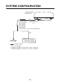
SYSTEM CONFIGURATION
Power supply
12/24 VDC
RADAR SENSOR
DRS4D-NXT
Multi Function Display
*
1
TZTL12F/TZTL15F
*
2
TZT9/TZT14/TZTBB
LAN
Power/LAN cable
1 m
: Local supply
*
1
Software upgrade to version 6.21 or later is required.
*
2
Software upgrade to version 6.01 or later is required.
Cable Assembly
CP03-36400/
CP03-36410/
CP03-36420/
CP03-36430
(10/15/20/30 m, 15 m is set as standard.)
: Standard supply

iv
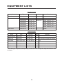
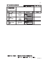
EQUIPMENT LISTS
Standard supply
Optional supply
*: After wiring is completed, waterproofing of LAN connector is required. Wrap the connector with
vinyl tape.
Name Type Code No. Qty Remarks
Radar Sensor RSB-135-115 000-029-247 1
Installation Materials CP03-37001 001-426-200 1
CP03-36400 000-027-211 Select one Cable Assembly, 10 m
CP03-36410 000-027-212 Cable Assembly, 15 m
CP03-36420 000-027-213 Cable Assembly, 20 m
CP03-36430 000-027-214 Cable Assembly, 30 m
Spare Parts SP03-18101 001-426-190 1 Fuses
Name Type Code No. Qty Remarks
Radome Mount OP03-208 001-078-340 1
Retrofit Kit OP03-239 001-426-250 1 For DRS2D, DRS4D and DRS6A
LAN Cable MOD-Z072-020+ 001-167-880-10 1 2m
LAN Cable MOD-Z072-050+ 001-167-890-10 1 5m
LAN Cable MOD-Z072-100+ 001-167-900-10 1 10m
Joint Box TL-CAT-012 000-167-140-10 1 For LAN cable extension

v
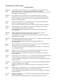
FOREWORD
General Information about DRS4D-NXT
• TARGET ANALYZER* function displays targets which is moving and getting close to own ship
in red and other targets in different colors. Speed analyzing range is ±50 kn.
* Requires a GPS sensor. When you change the setting of [Target Analyzer Mode] to [Rain],
rain clutter is displayed.
• AUTO TARGET ACQUIRE function automatically acquires only the targets which are moving
and getting close to own ship within the range of 3 NM by Doppler calculation. Automatic Dop-
pler function will be activated when there is a target which approaches own ship with the speed
of over 3 kn.
* The judged speed of target is dependent on its vector towards own ship.
• RezBoost provides azimuth resolution equivalent to comparable open-array radar.
Note: Refer to the Operator’s Manual for your Multi Function Display regarding the above new
functions.
• Instant ON function. This radar sensor does not have a magnetron, therefore preheating of the
magnetron is unnecessary.
• Reduced electricity emission means no need to worry about the radiation hazard.
• Magnetron-less radar means no periodic replacement of magnetron or related parts.
• Retrofit from DRS2D, DRS4D or DRS6A is available using the existing cable.
Refer to the following document, supplied with the optional kit OP03-239: "Retrofit Procedures
for DRS4D-NXT (Type; C32-01501-x/Code no.; 000-191-116-xx).
• RACON (RAdar beaCON) and SART (Search And Rescue Transponder) within 0.5 to 1.5 NM
(Range dependant) can be displayed.
* The signal from RACON and SART is shown as a line.
• The maximum display range is 48 NM in the signal range mode.
• ARPA (Automatic Radar Plotting Aid) function applicable range is 12 NM.
* ARPA symbols are erased when switching between signal and dual range modes and vice
versa.
• Dual Range Mode has the following limitations.
- The maximum display range is 12 NM. (48 NM when single display)
- The maximum detection range is reduced a maximum of 20% compared to the single
display.
Progran No.
• 0359360-01.**
** denotes minor modifications.
CE declaration
• With regards to CE declarations, please refer to our website (www.furuno.com), for further in-
formation about RoHS conformity declarations.

1
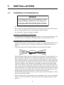
1. INSTALLATION
1.1 Installation Considerations
• Do not paint the radome, radar wave emission may be affected.
• Do not select a location that allows water to accumulate at the base of the sensor.
• Do not cut power/LAN cable or cable assembly when installing.
• Do not block air vent at the bottom of radome.
Connect to a distribution switchboard
• The radar sensor has no power switch. Therefore, it is recommended that you con-
nect the sensor to a distribution switchboard with a switch for power control.
Considerations for selecting a location for installation
• Install the radar sensor on radar arch, on a mast or on an appropriate platform. For
sailboats, a “radome mount” is optionally available for installing the sensor to a
mast.
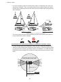
• This radar sensor emits a horizontal (360°) and a vertical (25°) beam.
Place the sensor where there is a good all-round view with, as far as possible, no
part of the ship’s superstructure or rigging intercepting the scanning beam. Any
small obstruction causes not only shadows and blind sectors, but also the deterio-
ration of antenna ability, such as beam width and side-lobe level. It also reduces the
radar's functionality, for example azimuth resolution, and can cause false echoes.
A mast for instance, with a diameter considerably less than the horizontal beam
width of the radiator, causes only a small blind sector, but a horizontal spreader or
cross trees in the same horizontal plane as the radar sensor would be a much more
serious obstruction; you would need to place the radar sensor well above or below
it. Be sure there are no metallic objects near the antenna. See illustrations on the
following page for typical placement on a sailboat and powerboat.
• Install the radar where large structures, such as a mast, will not be within 1 m diam-
eter from the center of radar.
• Select a location free of structures as much as possible, so as not to cause a blind
sector. A blind sector within the radar beam may prevent proper display of radar
echoes.
NOTICE
Do not apply paint, anti-corrosive sealant or contact
spray to coating or plastic parts of the equipment.
Those items contain organic solvents that can damage
coating and plastic parts, especially plastic connectors.
12.5°
12.5°
12.5°
12.5°

1. INSTALLATION
2
• It is rarely possible to place the radar sensor where a completely clear view in all
directions is available. Thus, you should determine the angular width and relative
bearing of any shadow sectors for their influence on the radar at the first opportunity
after installation.
• The radar sensor should not be operated or stored in any position other than the
proper operational position (upright).
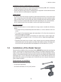
Consideration for selecting a location for installation (multiple radars)
• In case multiple radars are installed on a ship, DO NOT install the DRS4D-NXT
within the range of beam area emitted from other radar(s). Use the illustration below
for reference when selecting a suitable location for installation. The SSD inside the
RS4D-NXT will be damaged if it is within the radar beam emission area from other
radar.
Installation on a sailboat Installation on a powerboat
Typical installation on a sailboatand power boat
Radar sensor
Radar sensor
Radar sensor
Radar sensor
Radar sensor
Radar sensor
Rear View
(Rear View)
(Rear View)
More than 20°
More than 1 m
Other radar
More than 20°
More than 20°
More than 20°
Suitable location for installing
the DRS4D-NXT
Locate the radar out of the radar
beam (dark gray) of other radar.

1. INSTALLATION
3
Installation with the radiotelephone equipment
• Install the radome away from radiocommunication antennas (SSB, VHF, Inmarasat)
and GPS antenna to prevent radar interference.
• Install the radome away from the radiotelephone equipment so that electrical noise
does not affect the radiotelephone equipment.
Cable routing
• In order to reduce the chance of picking up electrical interference, avoid, where pos-
sible, routing the power/LAN cable and cable assembly near other electrical equip-
ment on-board. Also, avoid running the cable in parallel with other electrical cables.
• Make sure that the power/LAN cable and cable assembly do not run horizontally
and it is placed away from the cables carrying radio signal and antennas.
For large vessels
• When this radar sensor is to be installed on a large vessel, consider the following
points:
• The length of the pre-attached power/LAN cable is 1 m from radome to the con-
nector.
• The length of the standard supply cable assembly is 15 m from the connector to
the power supply and display.
• The power/LAN cable which runs between the radar sensor, power supply and
display comes in lengths of 10 m, 15 m, 20 m or 30 m. Select the length when
purchasing.
• Deposits and fumes from a funnel or other exhaust vent can adversely affect the
aerial performance and hot gases may distort the radiator portion. The radar sen-
sor must not be mounted where the temperature is more than 55°C (131°F).
1.2 Installation of the Radar Sensor
Determine the suitability of the mounting location BEFORE permanently mounting the
sensor. Incoming and outgoing signals may overlap one another depending on the
shape of the vessel, preventing communication between the radar and display. Set the
sensor on the selected location and connect the sensor to the distribution switchboard
and display unit. Turn on the sensor and the display unit. Check that the picture is up-
dated with each sweep on the display unit. Some trial and error may be necessary to
find a suitable location.
Required tools for installation
Prepare the tools shown to the right.
• A wrench for M10 bolts
• An electric drill with φ11 mm (0.43”) drill bit

1. INSTALLATION
4
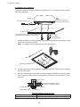
Installation on a platform
There are 5 steps necessary to install the radar sensor. The illustration below summa-
rizes the installation.
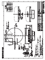
1. Set the supplied mounting template to the mounting location, then drill four fixing
holes in the mounting location.
Note: The holes must be parallel with the fore and aft line.
2. Put the radar sensor on the platform with the bow mark (U) on the sensor aligned
with the ship’s bow.
3. Use hex bolts (see the table below for bolt length), flat washers and spring wash-
ers to secure the radar sensor to the platform. The torque for the bolts is 19.6 to
24.5 N•m.
Platform thickness and bolt to use
Platform thickness Size of bolts to use
6 - 10 mm M10×25 (Supplied)
STERN
BOW
Align bow mark (Δ) on
radome with ship’s bow.
Power/LAN cable (1 m)
Holes drilled referring to the outline drawing
and the mounting template in this manual.
Platform
Hex bolt (M10×25)
Spring washer
Flat washer
BowBow
Mounting template
N
ote
: This templat
e
may have expande
d or s
h
runk slightly
.
Please
con
firm dimensions be
fore
use
.
ὀព㻦㻌㻌ᮏᆺ⣬䛿
ಖᏑ≧ែ䛻䜘
䜚ⱝᖸఙ⦰䛩䜛ሙྜ䛜䛒䜚䜎䛩䚹
㻌
㻌㻌㻌㻌
㻌㻌㻌㻌⏝䛾㝿䛻䛿ᑍἲ䜢
☜ㄆ
䛧䛶䛟䛰䛥䛔
䚹㻌
Drill
11mm (0.43'') hol
e
in dia.
(
f
our positio
ns)
䃥㻝
㻝㼙㼙㻌䜻䝸㻌㻔㻠䞃ᡤ㻕
㻝㻢㻜㼼
0.
5
mm (6
.3''
)
㻝㻢
㻜
㼼
0.
5mm (
6.3'')
㻢㻜
m
m (2.3
6'
')
CENT
E
R
O
F ANTENNA ROTAT
ION
䜰䞁䝔䝘ᅇ
㌿୰ᚰ
BO
W
⯪㤳᪉ྥ
De
cember
2
014
Printed
in
J
apan
C
32-
00702-
A1
㻰㻾㻿䝅䝸䞊䝈䝺
䝗䞊
䝮䝉䞁䝃䞊
ᆺ⣬
DRS Series
Radome Sensor
Template
䢲䢲䢲䢳䢸䢹䢶
䢷䢺䢳䢲
Platform
Sensor base
Flat washer
Hex bolt
Spring washer
Determine the length of bolts
according to platform thickness.

1. INSTALLATION
5
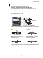
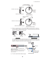
4. Connect the power/LAN cable to the cable assembly.
Follow these guidelines for laying the power/LAN cable
• The connectors must not strike any part of the vessel due to wind, etc.
• Do not apply any load to the connectors.
• If the cable is passed through a mast on a sailboat, be sure the cable does not
touch ropes (sheet, halyard, etc.).
• Do not let the cable touch the hull.
• The cable must be located where no tension is applied to the connectors. To
prevent tension, create a loop in the cable close to the sensor and tie the loop
with cable ties, as in the figure below.
• Wrap the junction of the connectors with self-vulcanizing tape for waterproofing.
• Fasten the cable to the mast, etc. at the neck of each connector with a cable tie.
• Make loops with surplus cable.
5. Connect the cable assembly to the power source and display unit.
Over 10 mm Local supply
Platform thickness Size of bolts to use
Loop cable and tie loop with cable ties.
The minimum
bend diameter
is 80 mm.
Self-vulcanizing tape
1) Wrap the junction of the connectors
with one layer of self-vulcanizing
tape.
2) Change wrap direction and wrap
one layer of the self-vulcanizing
tape again.
Self-vulcanizing tape
3) Wrap one layer of the vinyl tape over
the self-vulcanizing tape.
Vinyl tape
4) Change wrap direction and wrap one
layer of the vinyl tape again.
Vinyl tape

1. INSTALLATION
6
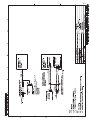
Installation with the radome mount
The optional radome mount lets you fasten the radar sensor to a mast on a sailboat.
Name, Type: Radome Mount, OP03-208
Code No.: 001-078-340
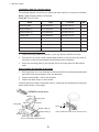
How to assemble the bracket
1. Fasten the fixing plates to brackets (1) and (2) with four M8×20 hex bolts.
2. Fit brackets (1) and (2) loosely with support plates (1) and (2) using four M4×12
hex bolts, so that the gap between the brackets can be adjusted.
3. Place the mounting plate on the bracket and fix it loosely with four M8×20 hex
bolts.
How to fasten the bracket to the mast
1. Drill eight holes of 6.5 mm diameter in the mast and fix the bracket with eight stain-
less steel rivets (local supply) of 6.4 mm diameter.
2. Fasten the bolts (M8 × 20) on the bracket.
3. Fasten the radar sensor to the bracket.
Connect the power cable to the power source, observing the guidelines for laying the
power cable shown on this page.
Name Type Code No. Qty
Mounting plate 03-018-9001-0 100-206-740-10 1
Support plate (1) 03-018-9002-3 100-206-753-10 1
Support plate (2) 03-018-9003-3 100-206-763-10 1
Fixing plate 03-018-9004-3 100-206-773-10 2
Bracket (1) 03-018-9005-0 100-206-780-10 1
Bracket (2) 03-018-9006-0 100-206-790-10 1
Hex bolt w/washer M8×20 SUS304 000-162-955-10 10
Hex bolt w/washer M4×12 SUS304 000-162-956-10 4
Mounting plate
Support plate (1)
Support plate (2)
Bracket (1)
Fixing plate
M8×20
ASSEMBLED RADOME MOUNT
M8×20
M8×20
M4×12
M10×25
How to fasten the sensor to the radome mount
Bracket (2)
Rivet
How to assemble the radome mount

1. INSTALLATION
7
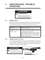
1.3 Wiring
1.3.1 Power requirement
The DRS4D-NXT requires either 12 VDC or 24 VDC power. Connect the red cable to
the positive terminal of ship’s battery; the blue cable to the negative terminal. The
black cable is a shielding cable for grounding.
1.3.2 Network cable connection
Connect the network cable to the multi function display device*. *Hereafter TZTL12F,
TZTL15F, TZT9, TZT14 and TZTBB are referred to as “multi function display device”.

8
2. INITIAL SETUP
2.1 Check Points After Installation
Before using the product, carry out the following:
• Mechanical checks
• Turning the power on and initial setup
Mechanical checks
Check below points before switching on the DRS4D-NXT.
• All washers are in place and bolts are fully fastened.
• All connections are secure and network cable is connected to the multi function dis-
play device.
• All connecting cables and wires are secured as instructed on page 4.
Turning the power on and initial setup
Use the information in this manual and the manual for multi function display device to
power the sensor and to proceed with initial setup.
1. Ensure that all personnel are clear of the antenna.
2. Press and hold down the power key of your multi function display device until the
unit is ON.
3. Take the appropriate action on your multi function display device to turn on the
DRS4D-NXT.
4. Check if the heading is correctly aligned - targets should appear at their correct
bearing relative to the boat’s bow. Adjust the alignment if necessary, referring to
section 2.2.
2.2 Initial Setup
Turn on the multi function display device, and do the initial setup for the antenna unit.
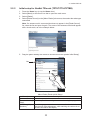
2.2.1 Initial setup for NavNet TZtouch2 (TZTL12F/TZTL15F)
1. Tap the [Home] icon to show the home screen and display mode settings.
2. Tap [Radar] from the [Settings] menu.
3. Tap [Radar Source], then select the appropriate antenna unit.
Note: If an antenna unit is connected but does not appear in the [Radar Source]
list, close the list and open it again. The name of the antenna unit should appear
with a check mark, as in the example below.

2. INITIAL SETUP
9
4. Drag the [Radar] menu display to show the menu item [Radar Initial Setup], then
tap [Radar Initial Setup].
5. Referring to the tables below, set up the radar.
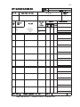
[Radar] menu - [Radar Initial Setup]
[Radar] menu - [Antenna Position]
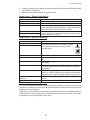
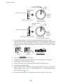
How to align the antenna heading
You have mounted the antenna unit facing straight ahead in the direction of the bow.
Therefore, a small but conspicuous target dead ahead visually should appear on the
heading line (zero degrees).
In practice, you will probably observe some small bearing error on the display because
of the difficulty in achieving accurate initial positioning of the antenna unit. The follow-
ing adjustment will compensate for the error.
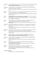
Menu item Description
[Antenna Rotation] Select the speed of antenna rotation.
[Antenna Heading Align] See "How to align the antenna heading" on page 9.
[Main Bang Suppression] If main bang appears at the screen center, slide the circle
icon so that the main bang disappears, while watching the
radar echo at the left-hand side of the display.
[Enable Sector Blanking] Up to two sectors may be selected for blanking (no trans-
mission). Select [ON] to enable this feature. Set the start
and end angles (0° to 359°).
[Enable Sector 2 Blanking]
Menu item Description
[Longitudinal (from bow)] Referring to the figure on the right, enter the
radar antenna positioning bow-stern (Longitu-
dinal) and port-starboard (Lateral) position
from the origin.
[Lateral (-Port)]
[Antenna Height] Select the height of the antenna above the waterline.
[Radar Monitoring] Display various information regarding the connected ra-
dar.
[TX Channel] Select [1], [2] or [3], the channel where the interference
is smallest.
[Target Analyzer Mode] You can emphasize rain clutter or target echoes when
the target analyzer is active. Select [Rain] or [Target] as
appropriate.
[Auto aquire by Doppler] When selecting [ON], approaching targets (ships, rain
clutter, etc.) within 3 NM from own ship are automatically
acquired by the Doppler calculated from the radar echo.
[Set Hardware To Factory
Default]
Resets the radar selected at [Radar Source] to factory
default.
[Reset Default Settings] Resets [Radar] menu settings to default.
Origin
Origin

2. INITIAL SETUP
10
1. Set your radar between 0.125 and 0.25 NM range and the head up mode.
You can select a range by using the pinch action. The range appears at the bottom
right of the screen. Range may also be selected using the slide bar displayed on
the right-hand side of the radar display area. Drag the bar up to zoom in, or down
to zoom out.
2. Turn the vessel’s bow toward a target.
3. Tap the [Home] icon to show the home screen and display mode settings.
4. Tap [Radar] to show the [Radar] menu.
5. Drag the [Radar] menu to show the [RADAR INITAL SETUP] menu.
6. Tap [Antenna Heading Align].
7. Key in the offset value so that the target is displayed at the very top of the screen
(setting range: +179.9° to -180°, +: clockwise direction, -: counterclockwise direc-
tion), then tap the icon.
8. Confirm that the target echo is displayed at correct bearing on the screen.
000
010
020
030
040
050
060
070
080
090
100
110
120
130
140
150
160
170
180
190
200
210
220
230
240
250
260
270
280
290
300
310
320
330
340
350
000
010
020
030
040
050
060
070
080
090
100
110
120
130
140
150
160
170
180
190
200
210
220
230
240
250
260
270
280
290
300
310
320
330
340
350
Correct bearing
(relative to heading)
a
Apparent
position
of target
Antenna oriented to port
Picture appears
deviated clockwise.
Apparent position
of target
b
Correct
bearing
(relative to
heading)
Antenna oriented to starboard Picture appears
deviated counterclockwise.
b
Target
Direction of bow mark
a
Target
Direction of bow mark
Range
Radar indications
HU
NM
Tx
3.650
Zoom outZoom in
Pinch action

2. INITIAL SETUP
11
2.2.2 Initial setup for NavNet TZtouch (TZT9/TZT14/TZTBB)
1. Press the Home key (or tap the Home icon).
2. Select [Menu] on the menu icon bar to open the main menu.
3. Select [Radar].
4. Select [Radar Source] on the [Menu Radar] sub menus, then select the radar type
connected.
Note: If a antenna unit is connected but does not appear in the [Radar Source]
list, close the list and open it again. The name of the antenna unit should appear
with a check mark, as in the example below.
5. Drag the [Menu Radar] sub menus to find the menu item [Radar Initial Setup].
Menu Radar (Radar Initial Setup)
Menu item Description
[Antenna Rotation] Select the speed of antenna rotation.
[Antenna Heading
Align]
See the topic of "How to align the antenna heading" on page 2-12.
[Main Bang Sup-
pression]
If main bang appears at the screen center, slide the circle icon so
that the main bang disappears, while watching the radar echo at
the left-hand side of the display.
Title

2. INITIAL SETUP
12
How to align the antenna heading
You have mounted the antenna unit facing straight ahead in the direction of the
bow. Therefore, a small but conspicuous target dead ahead visually should ap-
pear on the heading line (zero degrees).
In practice, you will probably observe some small bearing error on the display be-
cause of the difficulty in achieving accurate initial positioning of the antenna unit.
The following adjustment will compensate for the error.
[Enable Sector
Blanking]
Up to two sectors may be selected for blanking (no transmission).
Select [ON] to enable this feature. Set the start and end angles (0°
to 359°).
[Enable Sector 2
Blanking]
[Antenna Height] Select the height of the antenna above the waterline.
[Antenna Longitu-
dinal Position]
Enter the antenna positioning bow-stern (Longitudinal)
and port-starboard (lateral) position from the origin.
[Antenna Lateral
Position (-Port)]
[Radar Monitoring] Display various information regarding the connected radar.
[ARPA Advanced
Settings]
For service technician only. Do not change these settings. This-
menu item is available when setting the radar in transmit.
[TX Channel] Select [1], [2] or [3], the channel where the interference is smallest.
[Target Analyzer
Mode]
You can emphasize rain clutter or target echoes when the target
analyzer is active. Select [Rain] or [Target] as appropriate.
[Auto acquire by
Doppler]
When set to [ON], approaching targets (ships, rain clutter, etc.)
within 3 NM from own ship are automatically acquired by the Dop-
pler calculated from the radar echo.
[Hardware Factory
Default]
Resets the radar selected at [Radar Source] to factory default.
[Reset Default
Settings]
Resets the [Radar] menu settings to default.
Menu item Description
OriginOrigin

2. INITIAL SETUP
13
1) Select a range between 0.125 and 0.25 NM and set the mode to “head up“.
You can select a range by a pinch action. The range and range ring interval
appear at the bottom left of the screen.
For TZTBB, you can also control the range in the operation as follows. Tap
the radar scale box at the bottom left-hand corner of the screen to display the
slider bar. Drag the circle icon to set the range scale.
2) Turn the vessel’s bow toward a target.
000
010
020
030
040
050
060
070
080
090
100
110
120
130
140
150
160
170
180
190
200
210
220
230
240
250
260
270
280
290
300
310
320
330
340
350
000
010
020
030
040
050
060
070
080
090
100
110
120
130
140
150
160
170
180
190
200
210
220
230
240
250
260
270
280
290
300
310
320
330
340
350
Correct bearing
(relative to heading)
a
Apparent
position
of target
Antenna oriented to port
Picture appears
deviated clockwise.
Apparent position
of target
b
Correct
bearing
(relative to
heading)
Antenna oriented to starboard Picture appears
deviated counterclockwise.
b
Target
Direction of bow mark
a
Target
Direction of bow mark
4
Range Range ring interval
Range indications
Zoom outZoom in
Pinch action
1
Tap the area circled in the dashed line to
display the slider bar.
Note: You can switch between transmit and
stand-by by tapping the right side of the
radar scale box.
Drag the circle
icon to set the
range scale.
Slider bar
Zoom in
Zoom out
4NM
Current
range
1

2. INITIAL SETUP
14
3) Press the Home key (or tap the Home icon), then select [Menu] icon, [Radar],
and [Antenna Heading Align] in that order to show the numeric software key-
board.
4) Key in the offset value so that the target is at the very top of the screen (setting
range: +/- 0° to 180°, +: clockwise direction, -: counterclockwise direction),
then tap [Save].
5) Confirm that the target echo is displayed at correct bearing on the screen.
La pagina sta caricando ...
La pagina sta caricando ...
La pagina sta caricando ...
La pagina sta caricando ...
La pagina sta caricando ...
La pagina sta caricando ...
La pagina sta caricando ...
La pagina sta caricando ...
La pagina sta caricando ...
La pagina sta caricando ...
La pagina sta caricando ...
La pagina sta caricando ...
La pagina sta caricando ...
La pagina sta caricando ...
La pagina sta caricando ...
La pagina sta caricando ...
-
 1
1
-
 2
2
-
 3
3
-
 4
4
-
 5
5
-
 6
6
-
 7
7
-
 8
8
-
 9
9
-
 10
10
-
 11
11
-
 12
12
-
 13
13
-
 14
14
-
 15
15
-
 16
16
-
 17
17
-
 18
18
-
 19
19
-
 20
20
-
 21
21
-
 22
22
-
 23
23
-
 24
24
-
 25
25
-
 26
26
-
 27
27
-
 28
28
-
 29
29
-
 30
30
-
 31
31
-
 32
32
-
 33
33
-
 34
34
-
 35
35
-
 36
36


in altre lingue
- English: Furuno DRS4DNXT Installation guide
Documenti correlati
Altri documenti
-
Boston Whaler 280 Outrage Manuale del proprietario
-
-
Garmin GMR Fantom™ 18 Guida d'installazione
-
Regal 42 Fly-Grande Coupe Manuale del proprietario
-
Garmin Antena GPS/GLONASS GA 38 Guida d'installazione
-
 Navionics 11C Manuale utente
-
-
Simrad R2009/R3016 Radar Istruzioni per l'uso
-
 Greyline Instruments PDFM 5.0 Manuale utente
-
Nexus NXT-90 Manuale utente

