AVENTICS ECD-BVEC-15 Manuale del proprietario
- Tipo
- Manuale del proprietario

Betriebsanleitung | Operating instructions | Notice d’instruction |
Istruzioni per l’uso | Instrucciones de servicio | Bruksanvisning
R412025988/2017-08, Replaces: –, DE/EN/FR/IT/ES/SV
Kompaktejektor
Compact ejector
Éjecteur compact
Eiettore compatto
Eyector compacto
Kompaktejektor
ECD-BV

Deutsch
1 Zu dieser Dokumentation
Diese Anleitung enthält wichtige Informationen, um das
Produkt sicher und sachgerecht zu montieren und in
Betrieb zu nehmen.
O Lesen Sie diese Anleitung vollständig und
insbesondere das Kapitel 2 „Sicherheitshinweise“,
bevor Sie mit dem Produkt arbeiten.
Gültigkeit der Dokumentation
O Diese Dokumentation gilt für Kompaktejektoren der
Serie ECD-BV.
Zusätzliche Dokumentationen
O Beachten Sie auch die Anleitungen der übrigen
Anlagenkomponenten.
O Beachten Sie außerdem allgemein gültige, gesetzliche
und sonstige verbindliche Regelungen der
europäischen bzw. nationalen Gesetzgebung sowie die
in Ihrem Land gültigen Vorschriften zur
Unfallverhütung und zum Umweltschutz.
Darstellung von Informationen
Warnhinweise
In dieser Anleitung stehen Warnhinweise vor einer
Handlungsanweisung, bei der die Gefahr von Personen-
oder Sachschäden besteht. Die beschriebenen
Maßnahmen zur Gefahrenabwehr müssen eingehalten
werden.
Aufbau von Warnhinweisen
Bedeutung der Signalwörter
Symbole
SIGNALWORT
Art und Quelle der Gefahr
Folgen bei Nichtbeachtung der Gefahr
O Maßnahmen zur Abwehr der Gefahr
WARNUNG
Kennzeichnet eine gefährliche Situation, in der Tod oder
schwere Körperverletzung eintreten können, wenn sie
nicht vermieden wird.
VORSICHT
Kennzeichnet eine gefährliche Situation, in der leichte
bis mittelschwere Körperverletzungen eintreten können,
wenn sie nicht vermieden wird.
ACHTUNG
Kennzeichnet Sachschäden: Das Produkt oder die
Umgebung können beschädigt werden.
Wenn diese Information nicht beachtet wird, kann
das zu Verschlechterungen im Betriebsablauf
führen.
2 Sicherheitshinweise
Das Produkt wurde gemäß den allgemein anerkannten
Regeln der Technik hergestellt. Trotzdem besteht die
Gefahr von Personen- und Sachschäden, wenn Sie die
folgenden grundsätzlichen Sicherheitshinweise und die
Warnhinweise vor Handlungsanweisungen in dieser
Anleitung nicht beachten.
O Lesen Sie diese Anleitung gründlich und vollständig,
bevor Sie mit dem Produkt arbeiten.
O Bewahren Sie die Anleitung so auf, dass sie jederzeit
für alle Benutzer zugänglich ist.
O Geben Sie das Produkt an Dritte stets zusammen mit
der Betriebsanleitung weiter.
Bestimmungsgemäße Verwendung
Der Ejektor ist ausschließlich dazu bestimmt, in eine
Maschine bzw. Anlage eingebaut oder mit anderen
Komponenten zu einer Maschine bzw. Anlage
zusammengefügt zu werden.
O Halten Sie die in den technischen Daten genannten
Betriebsbedingungen und Leistungsgrenzen ein.
Verwenden Sie als Medium ausschließlich neutrale
Gase gemäß EN 983.
O Verwenden Sie den Ejektor ausschließlich zur
Vakuumerzeugung in Pneumatikanlagen.
Kompaktejektoren sind für den professionellen Gebrauch
und nicht für die private Verwendung bestimmt. Sie dürfen
Kompaktejektoren nur im industriellen Bereich einsetzen
(Klasse A nach DIN EN 55011). Für den Einsatz im
Wohnbereich (Wohn-, Geschäfts- und Gewerbebereich) ist
eine Einzelgenehmigung bei einer Behörde oder Prüfstelle
einzuholen. Die bestimmungsgemäße Verwendung
schließt auch ein, dass Sie diese Anleitung und
insbesondere das Kapitel 2 „Sicherheitshinweise“
vollständig gelesen und verstanden haben.
Nicht bestimmungsgemäße Verwendung
O Verwenden Sie den Ejektor nicht in
explosionsgefährdeten Bereichen.
O Saugen Sie mit dem Ejektor keine Flüssigkeiten,
aggressive oder brennbare Gase und Schüttgüter
(z. B. Granulate) an.
Qualifikation des Personals
Die Montage, Inbetriebnahme, Demontage und
Instandhaltung (inkl. Wartung und Pflege) erfordern
grundlegende mechanische und pneumatische
Kenntnisse sowie Kenntnisse der zugehörigen
Fachbegriffe. Um die Betriebssicherheit zu gewährleisten,
dürfen diese Tätigkeiten daher nur von einer
entsprechenden Fachkraft oder einer unterwiesenen
Person unter Leitung einer Fachkraft durchgeführt
werden. Eine Fachkraft ist, wer aufgrund seiner
fachlichen Ausbildung, seiner Kenntnisse und
Erfahrungen sowie seiner Kenntnisse der einschlägigen
Bestimmungen die ihm übertragenen Arbeiten beurteilen,
mögliche Gefahren erkennen und geeignete
Sicherheitsmaßnahmen treffen kann. Die Fachkraft muss
die einschlägigen fachspezifischen Regeln einhalten.
Das Fachpersonal muss auch mit dem
Steuerungskonzept der Anlage vertraut sein.
AVENTICS | ECD-BV | R412025988–BAL–001–AA | Deutsch 1

Allgemeine Sicherheitshinweise
W Beachten Sie die gültigen Vorschriften zur
Unfallverhütung und zum Umweltschutz im
Verwenderland und am Arbeitsplatz.
W Verwenden Sie AVENTICS-Produkte nur in technisch
einwandfreiem Zustand.
W Prüfen Sie das Produkt auf offensichtliche Mängel, wie
beispielsweise Risse im Gehäuse oder fehlende
Schrauben, Abdeckkappen, Dichtungen.
W Sie dürfen das Produkt grundsätzlich nicht verändern
oder umbauen.
W Das Öffnen des Produkts führt zur Beschädigung des
„tested“-Aufklebers. Dadurch erlischt die
Gewährleistung
W Die Gewährleistung erlischt bei fehlerhafter Montage.
W Belasten Sie das Produkt unter keinen Umständen in
unzulässiger Weise mechanisch.
W Schützen Sie das Produkt generell vor
Beschädigungen.
W Warnungen und Angaben zum Produkt dürfen nicht
mit Farbe etc. überdeckt werden, sondern müssen
stets gut lesbar sein.
W Für Schäden, die durch die Verwendung von anderen
als Originalersatzteilen oder Originalzubehör
entstehen, ist jegliche Haftung unsererseits
ausgeschlossen. Ausgenommen von der
Gewährleistung sind alle Verschleißteile.
Produkt- und technologieabhängige
Sicherheitshinweise
Bei der Montage
W Schalten Sie immer den relevanten Anlagenteil
drucklos und spannungsfrei, bevor Sie das Produkt
montieren bzw. Stecker anschließen oder ziehen.
Sichern Sie die Anlage gegen Wiedereinschalten.
W Verlegen Sie die Kabel und Leitungen so, dass diese
nicht beschädigt werden und niemand darüber
stolpern kann.
W Beachten Sie die Anschlusssymbole und
Anschlussbezeichnungen auf dem Ejektor.
W Verwenden Sie ausschließlich die vorgesehenen
Anschlussmöglichkeiten, Befestigungsbohrungen und
Befestigungsmittel.
W Stellen Sie vor der Inbetriebnahme sicher, dass alle
Dichtungen und Verschlüsse der Steckverbindungen
korrekt eingebaut und unbeschädigt sind, um zu
verhindern, dass Flüssigkeiten und Fremdkörper in
das Produkt eindringen können.
WARNUNG
Offene Vakuum-/Abluftanschlüsse und Sauggreifer
Verletzungsgefahr durch An- oder Einsaugen von
Augen oder anderen Körperteilen.
Verletzungsgefahr, da Abluft und eventuell angesaugte
Medien und Teile mit hoher Geschwindigkeit aus dem
Abluftanschluss austreten.
O
Blicken Sie niemals in saugende oder nicht saugende
Vakuumöffnungen (z. B. Vakuumanschlüsse oder
angeschlossene Sauggreifer).
O Blicken oder treten Sie niemals in den Abluftstrahl.
W Verwenden Sie für die Komponenten ausschließlich die
folgende Spannungsversorgung:
– 24-V-DC PELV-Stromkreise nach DIN EN 60204-1/
IEC 60204-1.
– Die Stromquelle für PELV muss ein
Sicherheitstrenntransformator nach IEC 61558-1
oder IEC 61558-2-6 sein oder eine Stromquelle, die
den gleichen Sicherheitsgrad erfüllt wie ein
Sicherheitstrenntransformator.
– Stellen Sie sicher, dass die Spannungsversorgung
des Netzteils immer kleiner als 300 V AC
(Außenleiter – Neutralleiter) ist.
W Verwenden Sie bei stark verschmutzter Vakuum-/
Umgebungsluft einen Vakuum-Tassenfilter VFC
zwischen dem Vakuumanschluss und zu
evakuierenden Volumina.
Bei der Inbetriebnahme
W Stellen Sie sicher, dass alle elektrischen und
pneumatischen Anschlüsse belegt oder verschlossen
sind. Nehmen Sie nur ein vollständig installiertes
Produkt in Betrieb.
Während des Betriebs
W Verwenden Sie den Ejektor nicht in
spritzwassergefährdeten Bereichen.
W Durch Druckluft können geschlossene Gefäße
explodieren. Durch Vakuum können geschlossene
Gefäße implodieren.
W Der Ejektor darf nur mit Schalldämpfer betrieben
werden. Blicken Sie niemals in den Abluftstrahl des
Schalldämpfers.
W Der Ejektor emittiert Schall. Wir empfehlen das Tragen
eines Gehörschutzes.
W Werden entgegen der bestimmungsgemäßen
Verwendung gefährlicher Staub, Ölnebel, Dämpfe,
Aerosole oder Ähnliches abgesaugt, gelangen diese in
die Abluft. Dies kann zu Vergiftungen führen.
W Der Betrieb außerhalb der spezifizierten
Leistungsgrenzen ist nicht zulässig. Fehlfunktion
sowie Zerstörung können die Folge sein.
W Es dürfen sich keine Personen im Transportbereich
der angesaugten Nutzlast aufhalten.
W Im Automatikbetrieb der Maschine/Anlage dürfen sich
keine Personen im Gefahrenbereich befinden.
Bei der Reinigung
W Verwenden Sie niemals Lösungsmittel oder
aggressive Reinigungsmittel. Reinigen Sie das Produkt
ausschließlich mit einem feuchten Tuch. Verwenden
Sie dazu ausschließlich Wasser und ggf. ein mildes
Reinigungsmittel.
W Verwenden Sie zur Reinigung keine
Hochdruckreiniger.
Bei der Instandhaltung und Instandsetzung
W Stellen Sie sicher, dass keine Leitungsverbindungen,
Anschlüsse und Bauteile gelöst werden, solange die
Anlage unter Druck und Spannung steht. Sichern Sie
die Anlage gegen Wiedereinschalten.
AVENTICS | ECD-BV | R412025988–BAL–001–AA | Deutsch 2

Ejektor pneumatisch anschließen
W Es darf nur ausreichend gewartete Druckluft
eingesetzt werden (Luft oder neutrales Gas gemäß
EN 983, gefiltert 5 μm, geölt oder ungeölt).
W Bei starkem saugseitigem Schmutzanfall (Staub,
Späne …) empfehlen wir den Einsatz von externen
Filtern, z. B. VFI 6/4 für BV 07/10 bzw VFI 8/6 für
BV 15.
W Schmutzpartikel oder Fremdkörper in den
Anschlüssen des Ejektors oder in den Schlauch- oder
Rohrleitungen können die Funktion des Ejektors stören
oder zum Funktionsverlust führen.
W Verlegen Sie Schlauch- und Rohrleitungen möglichst
kurz.
W Durch zu klein gewählte Innendurchmesser auf der
Druckluftseite wird nicht genügend Druckluft
zugeführt. Der Ejektor erreicht seine Leistungsdaten
dadurch nicht.
W Ein zu klein gewählter Innendurchmesser auf der
Vakuumseite bewirkt einen zu hohen
Strömungswiderstand. Dadurch sinkt die Saugleistung
und die Ansaugzeiten erhöhen sich. Außerdem
verlängern sich die Abblaszeiten.
W Verwenden Sie für den Ejektor nur die empfohlenen
Schlauch- oder Rohrinnendurchmesser. Wenn dies
nicht möglich ist, verwenden Sie den nächstgrößeren
Durchmesser.
Empfohlene Innendurchmesser
So schließen Sie den Ejektor pneumatisch an, siehe
Abbildung :
1. Schalten Sie den relevanten Anlagenteil drucklos.
2. Verlegen Sie die Schläuche knick- und quetschfrei.
3. Verbinden Sie den Druckluftschlauch mit dem
Druckluftanschluss (5) und den Vakuumschlauch mit
dem Vakuumanschluss (4).
VORSICHT
Anlage steht im Betrieb unter Druck
Das Arbeiten an der Anlage unter Druck kann zu
Verletzungen und Beschädigungen führen.
O Entlüften Sie vor dem Arbeiten an der Anlage alle
relevanten Anlagenteile.
ECD-BV-EC-...
Leistungs-
klasse
Innendurchmesser [mm]
1)
1)
Bezogen auf eine maximale Schlauchlänge von 2 m. Bei
größeren Schlauchlängen wählen Sie die Querschnitte
entsprechend größer.
Druckluftseitig Vakuumseitig
07 4 4
10 4 4
15 4 6
4
1
3Lieferumfang
Im Lieferumfang sind enthalten:
W 1 Kompaktejektor ECD-BV
W Betriebsanleitung
4 Zu diesem Produkt
Produktübersicht
In Abb. ist der Kompaktejektor ECD-BV dargestellt.
Funktionsbeschreibung
Vakuumerzeugung (Ansaugen des Werkstücks)
Der Ejektor ist zum Teilehandling mittels Vakuum in
Verbindung mit Saugsystemen konzipiert. Angesteuert
wird der Ejektor über die Vorsteuerventile. Über das
Vorsteuerventil „Saugen“ wird die Venturidüse aktiviert
bzw. deaktiviert. Bei der NO-Variante wird die Venturidüse
bei anstehender Spannung deaktiviert, bei der NC-
Variante hingegen aktiviert. Die integrierte
Rückschlagklappe verhindert bei angesaugten Objekten
mit dichter Oberfläche ein Abfallen des Vakuums.
Abblasen (Ablegen des Werkstücks)
Über das Vorsteuerventil „Abblasen“ wird der
Vakuumkreis des Ejektors mit Druckluft beaufschlagt.
Hiermit wird ein schneller Vakuumabbau und somit ein
schnelles Ablegen des Werkstücks gewährleistet.
Produktbeschreibung
Varianten
J
eder Ejektor hat eine genaue Artikelbezeichnung
(z. B. ECD-BV-EC-07-NO)
. Die Aufschlüsselung der
Artikelbezeichnung ergibt sich wie folgt:
O Entnehmen Sie weitere Details zu Ihrer Variante dem
Typenschild, siehe Abbildung .
5Montage
Ejektor montieren
Der Ejektor kann wahlweise mit Schrauben oder mittels
Hutschienenklemme montiert werden, siehe
Abbildung und . Abmessungen siehe Abbildung .
Typ ECD-BV
Funktionsweise:
elektrisch
EC
Über den Steckanschluss der
Vorsteuerventile
Leistungsklasse 07; 10; 15
Ruhestellung NO (normally open)
stromlos saugend
NC (normally
closed) stromlos
nicht saugend
Bei der Montage der Befestigungsschrauben wird
die Verwendung von Unterlegscheiben empfohlen.
1
1
1
3
1
3
1
3
1
2
AVENTICS | ECD-BV | R412025988–BAL–001–AA | Deutsch 3

Ejektor elektrisch anschließen
O Verwenden Sie ausschließlich Schutzkleinspannung
(PELV) und sorgen Sie für eine sichere elektrische
Trennung der Betriebsspannung gemäß EN 60204.
O Zum direkten Anschluss des Ejektors an die Steuerung
können AVENTICS-Anschlussleitungen verwendet
werden, siehe „Zubehör“.
So schließen Sie den Ejektor elektrisch an, siehe
Abbildung :
1. Schalten Sie den relevanten Anlagenteil
spannungsfrei.
2. Verlegen Sie die Kabel knick- und quetschfrei.
3. Verbinden Sie die Spannungsversorgung mit den
Vorsteuerventilen (1, 2).
6 Inbetriebnahme und Betrieb
VORSICHT
Anlage steht im Betrieb unter elektrischer Spannung
Das Arbeiten an der Anlage unter Spannung kann zu
Verletzungen durch Stromschlag oder zu
Beschädigungen der Komponenten führen.
O Schalten Sie vor dem Arbeiten an der Anlage alle
relevanten Anlagenteile spannungsfrei.
O V
erbinden und trennen Sie Steckverbindungen nur,
wenn alle relevanten Anlageteile spannungsfrei sind.
Beim Anschluss der Ventile muss keine Polarität
beachtet werden.
Stecker für Ventile müssen einrasten.
VORSICHT
Personenschäden oder Sachschäden durch
Nichteinhaltung der fachspezifischen Regeln
Der Betrieb des Ejektorsystems ohne Netzgeräte und
ohne Einhaltung der Norm EN 60204 kann zu
Personenschäden und zur Beschädigung des Systems
und der daran angeschlossenen Komponenten führen.
O Betreiben Sie das System ausschließlich über
Netzgeräte mit Schutzkleinspannung (PELV) und
sicherer elektrischer Trennung der
Versorgungsspannung gemäß EN 60204.
O Steckverbinder nicht unter Spannung verbinden oder
trennen.
1
Generelle Funktionen
Einstellung Abblasvolumenstrom
Siehe Abb. „Aufbau des Ejektors“.
Unterhalb des Vakuumanschlusses befindet sich eine
Drosselschraube zum Einstellen des
Abblasvolumenstroms.
O Um den Volumenstrom zu verriegeln, drehen Sie die
Drosselschraube im Uhrzeigersinn (nach rechts).
O Um den Volumenstrom zu erhöhen, drehen Sie die
Drosselschraube gegen den Uhrzeigersinn (nach
links).
Die Drosselschraube ist beidseitig mit einem Anschlag
versehen.
Inbetriebnahme
Der Ejektor darf erst in Betrieb genommen werden, wenn
er in die Maschine/die Anlage, für die er bestimmt ist,
eingebaut ist.
Erstmalige Inbetriebnahme und
Wiederinbetriebnahme nach Stillstand
1. Stellen Sie sicher, dass alle elektrischen und
pneumatischen Anschlüsse des Ejektors korrekt
verbunden sind und fest sitzen.
2. Schalten Sie die Betriebsspannung ein.
3. Schalten Sie den Betriebsdruck ein.
Betrieb
Angesteuert wird der Ejektor über die Vorsteuerventile.
Der Abblasvolumenstrom kann über die Drosselschraube
eingestellt werden. Siehe auch „Technische Daten“.
WARNUNG
Offene Vakuum-/Abluftanschlüsse und Sauggreifer
Verletzungsgefahr durch An- oder Einsaugen von
Augen oder anderen Körperteilen.
Verletzungsgefahr, da Abluft und eventuell angesaugte
Medien und Teile mit hoher Geschwindigkeit aus dem
Abluftanschluss austreten.
O Blicken Sie niemals in saugende oder nicht
saugende Vakuumöffnungen (z. B.
Vakuumanschlüsse oder angeschlossene
Sauggreifer).
O Blicken oder treten Sie niemals in den Abluftstrahl.
Den Anschlag der Drosselschraube nicht
überdrehen! Technisch bedingt ist immer ein
Mindestvolumenstrom von ca. 10 % notwendig.
Der Abblasvolumenstrom kann zwischen 10 %
und 100 % eingestellt werden.
1
AVENTICS | ECD-BV | R412025988–BAL–001–AA | Deutsch 4

8Demontage
1. Schalten Sie den relevanten Anlagenteil drucklos und
spannungsfrei.
2. Um die Vorsteuerventile zu demontieren, betätigen Sie
den Rasthebel.
9 Fehlersuche und
Fehlerbehebung
VORSICHT
Anlage steht im Betrieb unter Druck
Das Arbeiten an der Anlage unter Druck kann zu
Verletzungen und Beschädigungen führen.
O Entlüften Sie vor dem Arbeiten an der Anlage alle
relevanten Anlagenteile.
VORSICHT
Anlage steht im Betrieb unter elektrischer Spannung
Das Arbeiten an der Anlage unter Spannung kann zu
Verletzungen durch Stromschlag oder zu
Beschädigungen der Komponenten führen.
O Schalten Sie vor dem Arbeiten an der Anlage alle
relevanten Anlagenteile spannungsfrei.
O
Verbinden und trennen Sie Steckverbindungen nur,
wenn alle relevanten Anlageteile spannungsfrei sind.
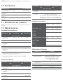
Störung Mögliche Ursache Abhilfe
Vakuumniveau
wird nicht
erreicht oder
Vakuum wird
zu langsam
aufgebaut
Schalldämpfer
verschmutzt
Schalldämpfer
austauschen
Leckage in
Schlauchleitung
Schlauchverbindun-
gen überprüfen
Leckage am
Sauggreifer
Sauggreifer
überprüfen
Betriebsdruck zu
gering
Betriebsdruck
erhöhen
(max. Grenzen
beachten)
Innendurch-
messer der
Schlauchleitung
zu klein
Siehe Empfehlungen
für Schlauchdurch-
messer
Nutzlast kann
nicht
festgehalten
werden
Vakuumniveau zu
gering
Betriebsdruck
erhöhen (max.
Grenzen beachten)
Sauggreifer zu
klein
Größeren
Sauggreifer
auswählen
AVENTICS | ECD-BV | R412025988–BAL–001–AA | Deutsch 5
7 Instandhaltung und
Instandsetzung
Äußere Verschmutzung
Schalldämpfer
Der offene Schalldämpfer kann bei starker Einwirkung
von Staub, Öl usw. so verschmutzen, dass sich die
Saugleistung dadurch verringert. Er sollte dann
ausgetauscht werden. Eine Reinigung ist auf Grund der
Kapillarwirkung des porösen Materials nicht
empfehlenswert.
Ersatz- und Verschleißteile
ACHTUNG
Beschädigungen und Störungen durch eindringende
Flüssigkeiten oder Kontakt mit aggressiven Medien
Eindringende Flüssigkeiten sowie die Verwendung von
Lösungsmitteln und aggressiven Reinigungsmitteln
können zu Beschädigungen und Störungen führen.
Die sichere Funktion des Ejektors ist dadurch nicht
mehr gewährleistet.
O Reinigen Sie den Ejektor ausschließlich mit einem
feuchten Tuch aus nicht faserndem Gewebe.
O Verwenden Sie zur Reinigung ausschließlich Wasser
und ggf. ein mildes Reinigungsmittel.
O Achten Sie darauf, dass der Schalldämpfer und die
Steuerung nicht mit Flüssigkeit getränkt werden.
O Verwenden Sie keinen Hochdruckreiniger.
ACHTUNG
Beschädigung durch zu hohe Krafteinwirkung
Zu hohe Krafteinwirkung beim Anziehen/Festziehen der
Befestigungsschrauben kann zu Schäden am Gehäuse
führen.
O Beachten Sie beim Festziehen der
Befestigungsschrauben am Schalldämpfermodul
das maximale Anzugsmoment von 0,5 Nm.
Es wird empfohlen, beim Austausch des
Schalldämpfereinsatzes auch die Dämmscheibe
auszutauschen.
Bezeichnung Materialnummer
Schalldämpfereinsatz R412026154
Vorsteuerventil „Abblasen“
für Ejektortyp NO/NC /
Vorsteuerventil „Saugen“
für Ejektortyp NC
R412026285
Vorsteuerventil „Saugen“
für Ejektortyp NO
R412026286
Dämmscheibe R412026156

10 Zubehör
11 Entsorgung
Entsorgen Sie den Ejektor nach den nationalen
Bestimmungen Ihres Landes.
12 Technische Daten
Elektrische Parameter
Mechanische Daten
Bezeichnung Materialnummer
Verbindungskabel, 3 m, 2-polig R422003278
Hutmuttern für unbelegte Plätze R412026153
Vakuum-Inlinefilter, Serie VFI, VFI-6/4 R412010112
Vakuum-Inlinefilter, Serie VFI, VFI-8/6 R412010113
Parameter Sym-
bol
Grenzwert Ein-
heit
Bemerkung
min. typ. max.
Versorgungs-
spannung
U
A
22,8 24 26,4 V
DC
PELV
1)
1)
Die Versorgungsspannung muss den Bestimmungen gemäß
EN 60204 (Schutzkleinspannung) entsprechen.
ECD-BV-EC-xx-NO
Nennstrom
aus U
A
2)
2)
Gleichzeitige Ansteuerung der Ventile „Saugen“ und „Abblasen“
3)
Getrennte Ansteuerung der Ventile „Saugen“ und „Abblasen“
I
A
– – 110 mA U
A
= 24 V
ECD-BV-EC-xx-NC
Nennstrom
aus U
A
3)
I
A
––55mAU
A
= 24 V
Parameter Sym-
bol
Grenzwert Ein-
heit
Bemer-
kung
min. typ. max.
Arbeits-
temperatur
T
amb
050°C
Lager-
temperatur
T
Sto
-10 60 °C
Luftfeuchtigkeit H
rel
10 90 %rf konden-
satfrei
Schutzart – – IP65
Betriebsdruck P 2 4 6 bar
Betriebs-
medium
Neutrale Gase gemäß EN 983 z. B. Luft,
Stickstoff und Edelgase (z. B. Argon,
Helium, Neon), gefiltert 5 μm,
geölt oder ungeölt, Druckluftqualität
Klasse 3-3-3 nach ISO 8573-1
Mechanische Parameter
Verwendete Materialien
Typ ECD-BV-
EC-07
ECD-BV-
EC-10
ECD-BV-
EC-15
Düsengröße [mm] 0,7 1,0 1,5
Max. Vakuum
1)
[%] 85 85 85
Saugvermögen
1)
[l/min] 16 34 63
Max. Abblasvermögen
1)
[l/min]
130 130 130
Luftverbrauch
1)
[l/min]
1)
bei 4 bar
25 42 95
Schallpegel freies
Ansaugen
1)
[dBA]
61 66 68
Schallpegel angesaugt
1)
[dBA]
58 59 60
Gewicht [kg] 0,195 0,195 0,195
Bauteil Werkstoff
Grundkörper PA6-GF, Aluminiumlegierung
eloxiert
Innenteile Aluminiumlegierung,
Aluminiumlegierung eloxiert,
Messing, Stahl verzinkt, Edelstahl,
PU, POM
Schalldämpfer-
einsatz
PE porös
Dichtungen NBR
Schmierungen silikonfrei
Schrauben Stahl verzinkt
AVENTICS | ECD-BV | R412025988–BAL–001–AA | Deutsch 6

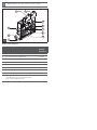
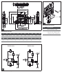
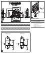
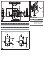
Abbildungen: Ansicht variiert je nach Serie.
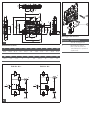
Aufbau des Ejektors
Beschreibung Max.
Anzugs-
momente
1 Vorsteuerventil „Saugen“ 0,2 Nm
2 Vorsteuerventil „Abblasen“ 0,2 Nm
3 Drosselschraube Abblasen
4 Vakuumanschluss (Kennzeichnung 2*) 4 Nm
5 Druckluftanschluss D6
6 Schalldämpferdeckel 0,5 Nm
7 Befestigungsbohrung 2 Nm
8 Abluftausgang (Kennzeichnung 3*)
9 Typenschild inkl. Fertigungsdatum:
<yy>W<ww> (yy =Fertigungsjahr,
ww= Fertigungswoche>
*Kennziffer auf dem Ejektor, siehe Abbildung.
1
9
4
3
5
6
7
9
8
1 2

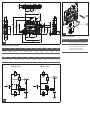
Abmessungen (in mm)
L L1 L2 L3 L4 B B1 H H1 H2 H3
86,2 102,5 81,4 22 29,5 18 18,6 77,5 97 40,8 47,5
H4 H5 d d1 d2 d3 X1 X2 Y1 Y2
16,5 5,5 4,4 6 6 2,6 36,9 16 12 12
Pneumatikschaltpläne
ECD-BV...NO... ECD-BV...NC...
1
3
2
1
3
2
4
B
B1
L4 X2
d3
Y2
H3
H4
H5
d
H1
H
G2 (d2)
L2
L
L3 X1
L1
H2
G1 (d1)
Y1
2
1
2
3
Ejektor montieren
Position Beschreibung
1 Befestigungschraube M4
2 Hutschienenklemme für
Hutschiene TS35 inkl.
Kunststoffschneid-
schrauben (optional)

English
1 About this Documentation
These instructions contain important information for the
safe and appropriate assembly and commissioning of the
product.
O Read these instructions carefully, especially chapter 2
“Notes on Safety”, before you start working with the
product.
Documentation validity
O This documentation is valid for ECD-BV series compact
ejectors.
Additional documentation
O Also follow the instructions for the other system
components.
O Please also observe the generally relevant, statutory
and other binding regulations of European and national
legislation and the national regulations for accident
prevention and environmental protection in your
country.
Presentation of information
Warnings
In this document, there are safety instructions before the
steps whenever there is a danger of personal injury or
damage to the equipment. The measures described to
avoid these hazards must be followed.
Structure of warnings
Bedeutung der Signalwörter
Symbols
SIGNAL WORD
Hazard type and source
Consequences of non-observance
O Measures to avoid these hazards
WARNING
Indicates a hazardous situation which, if not avoided,
could result in death or serious injury.
CAUTION
Indicates a hazardous situation which, if not avoided,
could result in minor or moderate injuries.
NOTICE
Indicates that damage may be inflicted on the product or
the environment.
Operation may be impaired if this information is
disregarded.
2 Notes on Safety
The product has been manufactured according to the
accepted rules of current technology. Even so, there is a
risk of injury or damage if the following general safety
instructions and the specific warnings given in this
instruction manual are not observed
O Please read all these instructions carefully before
working with the product.
O Keep these instructions in a location where they are
accessible to all users at all times.
O Always include the operating instructions when you
pass the product on to third parties.
Intended use
The ejector is exclusively intended for installation in a
machine or system or for combination with other
components to form a machine or system.
O Use is permitted only under the operating conditions
and within the performance limits listed in the
technical data. Only use neutral gases in accordance
with EN 983 as media.
O Exclusively use the ejector for vacuum generation in
pneumatic systems.
Compact ejectors are intended for professional use only
and not for private use. Compact ejectors may only be
used for industrial applications (class A in accordance
with DIN EN 55011). An individual license must be
obtained from the authorities or an inspection center for
systems that are to be used in a residential area
(residential, business, and commercial areas).
Intended use includes having read and understood these
instructions, especially chapter 2 “Notes on Safety”.
Improper use
O Do not use the ejector in explosive areas.
O Do not use the ejector to suction fluids, aggressive or
flammable gases, and bulk materials (e.g. granulate).
Personnel qualifications
Assembly, disassembly, commissioning, and maintenance
(incl. service and care) require basic mechanical and
pneumatic knowledge, as well as knowledge of the
appropriate technical terms.
In order to ensure operational safety, these tasks may only
be carried out by qualified personnel or an instructed
person under the direction of qualified personnel.
Qualified personnel are those who can recognize possible
hazards and institute the appropriate safety measures,
due to their professional training, knowledge, and
experience, as well as their understanding of the relevant
regulations pertaining to the work to be done. Qualified
personnel must observe the rules relevant to the subject
area.
The trained personnel must also be familiar with the
control concept of the system.
AVENTICS | ECD-BV | R412025988–BAL–001–AA | English 7

General safety instructions
W Observe the valid local regulations in the country of use
to protect the environment and avoid workplace
accidents.
W Only use AVENTICS products that are in perfect
working order.
W Examine the product for obvious defects, such as
cracks in the housing or missing screws, caps, or
seals.
W Do not modify or convert the product.
W Opening the product will destroy the “tested” label.
This voids the warranty.
W The warranty will not apply if the product is incorrectly
assembled.
W Do not place any improper mechanical loads on the
product under any circumstances.
W Generally protect the product from damage.
W Product warnings and information must be legible,
i.e. not covered by paint, etc.
W No liability is assumed for damage caused by the use
of non-original spare parts or accessories. All wear
parts are excluded from warranty.
Safety instructions related to the product
and technology
On assembly
W Make sure the relevant system component is not under
pressure or voltage before assembling the product or
when connecting and disconnecting plugs. Protect the
system against being restarted.
W Lay cables and lines so that they cannot be damaged
and no one can trip over them.
W Observe the connection symbols and connection
designations on the ejector.
W Only use the designated connection options, mounting
holes, and mounting material.
W Before commissioning, make sure that all the
connection seals and locks are properly installed and
undamaged to prevent fluids and foreign bodies from
penetrating the product.
WARNING
Open vacuum/exhaust air connections and
vacuum cup
Risk of injury by suctioning of eyes or other parts of the
body.
Risk of injury due to exhaust air and any other parts and
debris that may have been drawn in being emitted from
the exhaust air connection at high speed.
O Never look into vacuum openings, neither suctioning
or not suctioning (e.g. vacuum connections or
connected vacuum cups).
O Never look into or enter the exhaust air stream.
W Only use the following power supply for the
components:
– 24 V DC PELV circuits in accordance with
DIN EN 60204-1/IEC 60204-1.
– The PELV power source must be a safety isolation
transformer in accordance with IEC 61558-1 or
IEC 61558-2-6, or a power source offering the same
degree of safety as a safety isolation transformer.
– Make sure that the power supply of the power pack
is always less than 300 V AC (outer conductor –
neutral wire).
W In case of heavily contaminated vacuum/ambient air,
use a VFC cup version vacuum filter between the
vacuum connection and the volumes to be evacuated.
During commissioning
W Check that all the electrical and pneumatic connections
are allocated or closed. Only commission fully installed
products.
During operation
W Do not use the ejector in areas that are not
splashwater-proof.
W Closed containers may explode due to compressed air.
Closed containers may implode due to vacuum.
W Only operate the ejector with a silencer. Never look into
the exhaust air stream of the silencer.
W The ejector emits acoustic noise. We recommend
wearing ear protectors.
W If, contrary to the intended use, hazardous dust, oil
mist, vapors, aerosols, or the like are extracted, they
will mix with the exhaust air. This can lead to
poisoning.
W Operating the product beyond the specified
performance limits is not permitted. Malfunctions and
destruction may result.
W No persons are allowed in the transporting area of the
suctioned useful load.
W With the machine/system in automatic mode, no
persons are allowed in the danger zone.
During cleaning
W Never use solvents or aggressive detergents. Only
clean the product using a damp cloth. Only use water
and, if necessary, a mild detergent.
W Do not use high-pressure cleaners for cleaning.
During service and repairs
W Make sure that no line connections, ports and
components are disconnected as long as pressure and
voltage are applied in the system. Protect the system
against being restarted.
AVENTICS | ECD-BV | R412025988–BAL–001–AA | English 8

Connecting the ejector pneumatics
W Use only compressed air from an appropriately
maintained system (air or neutral gas in accordance
with EN 983, filtered to 5 μm, oiled or oil-free).
W We recommend using external filters for high levels of
accumulated dirt on the suction end (dust, chips, etc.):
for example, VFI 6/4 for BV 07/10 and VFI 8/6 for
BV 15.
W Dirt particles or foreign bodies in the ejector
connection or tubing or pipelines may impair the
ejector's function or lead to a malfunction.
W Route tubing and pipelines as short as possible.
W If the inside diameters selected for the compressed air
end are too small, the supply of compressed air will be
insufficient. As a result, the ejector will not achieve its
specified performance.
W If the inside diameter selected for the vacuum end is
too small, this will cause an excessively high flow
resistance. This will in turn decrease the suction
capacity and increase the suction time. Blow-off times
will also increase.
W Use only the tubing or pipe inside diameters that are
recommended for the ejector. If this is not possible, use
the next higher diameter.
Recommended inside diameters
Make the pneumatic connection for the ejector as follows,
see Fig :
1. Make sure the relevant system part is not under
pressure.
2. Lay the tubes so as not to bend or crush them.
3. Connect the compressed air tubing with the
compressed air connection (5) and the vacuum tubing
with the vacuum connection (4).
CAUTION
System is under pressure during operation
Working on the system under pressure can lead to
injuries and damage to property.
O Depressurize all relevant system parts prior to
performing work on the system.
ECD-BV-EC-...
Performance
class
Inside diameter [mm]
1)
1)
Based on a maximum tubing length of 2 m. In the case of
longer tubing lengths, select larger cross sections as
appropriate.
Compressed air
end
Vacuum end
07 4 4
10 4 4
15 4 6
4
1
3 Scope of Delivery
The scope of delivery includes:
W 1 compact ejector ECD-BV
W Operating instructions
4 About This Product
Product overview
Fig. shows compact ejector ECD-BV.
Function description
Vacuum generation (suctioning of workpiece)
The ejector is designed for handling parts using a vacuum
in conjunction with suctioning systems.
The ejector is actuated via the pilot valves. The “suction”
pilot valve activates and deactivates the Venturi nozzle. In
the NO variant, an applied voltage deactivates the Venturi
nozzle, while in the NC version it activates the nozzle.
On suctioned objects with leak-tight surface, the
integrated non-return valve prevents the vacuum from
dropping.
Blow off (placing down the workpiece)
The vacuum circuit of the ejector is pressurized with
compressed air via the “blow off” pilot valve. This mode is
used to ensure fast vacuum reduction and thus quick
placing of the workpiece.
Product description
Variants
Every ejector has an exact article designation
(e.g. ECD-BV-EC-07-NO). The breakdown for the article
designation is as follows:
O Refer to the name plate of your variant for further
details, see figure .
5 Assembly
Assembling the ejector
The ejector can be mounted either with screws or by using
a hat rail clamp, see Fig and .
See figure for dimensions.
Type ECD-BV
Operating mode:
electrical
EC
Via the pilot valve push-in fittings
Performance
class
07; 10; 15
Home position NO (normally open)
suction without
current
NC (normally
closed) no
suction without
current
When mounting the fastening screws,
we recommend using washers.
1
1
1
3
1
3
1
3
1
2
AVENTICS | ECD-BV | R412025988–BAL–001–AA | English 9

Electrically connecting the ejector
O Use protective extra low voltage (PELV) only and
provide for secure electrical isolation of the operating
voltage in accordance with EN 60204.
O For directly connecting the ejector to the controller,
use AVENTICS connecting cables, see “Accessories”.
Make the electrical connections for the ejector as follows,
see Fig. :
1. Make sure the relevant system part is not under
voltage.
2. Lay the cables so as not to bend or crush them.
3. Connect the power supply to the pilot valves (1, 2).
6 Commissioning and
Operation
CAUTION
System is under voltage during operation
Working on the system under voltage can lead to
injuries due to electric shock or damage to the
components.
O
Make sure that all relevant system parts are not under
voltage before performing work on the system.
O
Connect or disconnect plug connectors only if all
relevant system parts are without voltage.
No polarity needs to be observed when connecting
the valves.
Plugs for valves must click into place.
CAUTION
Personal injury or property damage caused
by non-compliance with specific technical rules
Operating the ejector system without power packs and
without complying with standard EN 60204 can result in
personal injuries and damage to the system and the
connected components.
O Only operate the system using power packs with
protective extra-low voltage (PELV) and safe electric
isolation of the supply voltage in accordance with
EN 60204.
O Do not connect or disconnect plug connectors under
voltage.
1
General functions
Setting the blow-off volume flow
See figure “Ejector design”.
Below the vacuum connection there is a flow control
screw for setting the blow-off volume flow.
O Turn the flow control screw clockwise (to the right) in
order to reduce the volume flow.
O Turn the flow control screw counterclockwise
(to the left) in order to increase the volume flow.
The flow control screw has a stop on both sides.
Commissioning
The ejector may only be commissioned after it has been
installed in the machine/system for which it is intended.
Commissioning for the first time and
recommissioning after downtime
1. Make sure that all electrical and pneumatic
connections of the ejector are correctly connected and
are firmly fitted.
2. Switch on the operating voltage.
3. Switch on the operating pressure.
Operation
The ejector is actuated via the pilot valves. The blow-off
volume flow can be set via the flow control screw. See also
“Technical Data”.
WARNING
Open vacuum/exhaust air connections and vacuum
cup
Risk of injury by suctioning of eyes or other parts of the
body.
Risk of injury due to exhaust air and any other parts and
debris that may have been drawn in being emitted from
the exhaust air connection at high speed.
O Never look into vacuum openings, neither suctioning
or not suctioning (e.g. vacuum connections or
connected vacuum cups).
O Never look into or enter the exhaust air stream.
Do not turn the flow control screw beyond its
stops! Due to technical reasons, a minimum
volume flow of approx. 10% is always required.
The blow-off volume flow can be set to a value
between 10% and 100%.
1
AVENTICS | ECD-BV | R412025988–BAL–001–AA | English 10

8Disassembly
1. Make sure the relevant system part is not under
voltage or pressure.
2. Actuate the locking lever in order to disassemble the
pilot valves.
9 Troubleshooting
CAUTION
System is under pressure during operation
Working on the system under pressure can lead to
injuries and damage to property.
O Depressurize all relevant system parts prior to
performing work on the system.
CAUTION
System is under voltage during operation
Working on the system under voltage can lead to
injuries due to electric shock or damage to the
components.
O
Make sure that all relevant system parts are not under
voltage before performing work on the system.
O
Connect or disconnect plug connectors only if all
relevant system parts are without voltage.
Malfunction Possible cause Remedy
Vacuum level
is not reached
or vacuum
builds up too
slowly
Silencer soiled Replace silencer
Leakage in tubing
line
Check tubing
connections
Leakage on
vacuum cup
Check vacuum cup
Operating
pressure too low
Increase the
operating pressure
(observe max. limits)
Inside diameter of
tubing line too
small
See
recommendations for
tubing diameter
Unable to hold
useful load
Vacuum level too
low
Increase the
operating pressure
(observe max. limits)
Vacuum cup too
small
Select larger vacuum
cup
AVENTICS | ECD-BV | R412025988–BAL–001–AA | English 11
7 Service and Repairs
External contamination
Silencer
The open silencer can become soiled if exposed to heavy
contamination by dust, oil, etc. and thus reduce the suction
capacity. It should be replaced in this case. Due to the
capillary effect of the porous material, cleaning is not
recommended.
Spare and wearing parts
NOTICE
Damage and disruptions due to penetrating fluids
or contact with aggressive media
Penetrating fluids and use of solvents and aggressive
cleaning agents can lead to damage and disruptions.
In this case, reliable ejector function can no longer be
guaranteed.
O Only clean the ejector with a damp, lint-free cloth.
O Only use water and, if necessary, a mild detergent
for cleaning.
O Make sure that the silencer and the controller are
not soaked in fluid.
O Do not use a high-pressure cleaner.
NOTICE
Damage due to excessive force
Exerting excessive force when tightening the mounting
screws can lead to damage to the housing.
O Observe the maximum torque of 0.5 Nm when
tightening the mounting screws on the silencer
module.
We recommend that you also replace the damping
plate when exchanging the silencer insert.
Designation Material number
Silencer insert R412026154
“Blow-off” pilot valve for ejector
type NO/NC / “Suction” pilot valve
for ejector type NC
R412026285
“Suction” pilot valve for ejector
type NO
R412026286
Damping plate R412026156

10 Accessories
11 Disposal
Dispose of the ejector in accordance with the national
regulations in your country.
12 Technical Data
Electrical parameters
Mechanical data
Designation Material number
Connecting cable, 3 m, 2-pin R422003278
Cap nuts for vacant ports R412026153
Vacuum filter Inline, series VFI, VFI-6/4
R412010112
Vacuum filter Inline, series VFI, VFI-8/6
R412010113
Parameter Sym-
bol
Limit Unit Comment
min. typ. max.
Supply voltage U
A
22.8 24 26.4 V
DC
PELV
1)
1)
The supply voltage must comply with the regulations in
accordance with EN 60204 (Protective extra-low voltage).
ECD-BV-EC-xx-NO
Nominal
current from
U
A
2)
2)
Simultaneous control of the “suction” and “blow-off” valves
3) Separate control of the “suction” and “blow-off” valves
I
A
– – 110 mA U
A
= 24 V
ECD-BV-EC-xx-NC
Nominal
current from
U
A
3)
I
A
––55mAU
A
= 24 V
Parameter Sym-
bol
Limit Unit Comment
min. typ. max.
Working
temperature
T
amb
050°C
Storage
temperature
T
Sto
-10 60 °C
Humidity H
rel
10 90 %rf non-
condensing
Protection
class
––IP65
Operating
pressure
P246bar
Operating
medium
Neutral gases in accordance with EN 983,
e.g. air, nitrogen, and inert gases
(e.g. argon, helium, neon), filtered to 5 μm,
oiled or oil-free, compressed air quality
class 3-3-3 as per ISO 8573-1
Mechanical parameters
Materials used
Type ECD-BV-
EC-07
ECD-BV-
EC-10
ECD-BV-
EC-15
Nozzle size [mm] 0.7 1.0 1.5
Max. vacuum
1)
[%] 85 85 85
Suction capacity
1)
[l/min] 16 34 63
Max. blow-off capacity
1)
[l/min]
130 130 130
Air consumption
1)
[l/min]
1)
at 4 bar
25 42 95
Noise level at free
suctioning
1)
[dBA]
61 66 68
Noise level, suctioned
1)
[dBA]
58 59 60
Weight [kg] 0.195 0.195 0.195
Component Material
Base body PA6-GF, aluminum alloy, anodized
Internal parts Aluminum alloy, anodized
aluminum alloy, brass, galvanized
steel, stainless steel, PU, POM
Silencer insert Porous PE
Seals NBR
Lubrication Silicone-free
Screws Galvanized steel
AVENTICS | ECD-BV | R412025988–BAL–001–AA | English 12

Figures: View varies according to the series.
Ejector design
Description Max.
tightening
torques
1 "Suction" pilot valve 0.2 Nm
2 "Blow-off" pilot valve 0.2 Nm
3 "Blow-off" flow control screw
4 Vacuum connection (identified as 2*) 4 Nm
5 Compressed air connection D6
6 Silencer cover 0.5 Nm
7 Mounting hole 2 Nm
8 Exhaust air outlet (identified as 3*)
9 Name plate incl. production date:
<yy>W<ww> (yy =year of production,
ww= week of production>
*Identification number on the ejector, see figure.
1
9
4
3
5
6
7
9
8
1 2

Dimensions (in mm)
L L1 L2 L3 L4 B B1 H H1 H2 H3
86.2 102.5 81.4 22 29.5 18 18.6 77.5 97 40.8 47.5
H4 H5 d d1 d2 d3 X1 X2 Y1 Y2
16.5 5.5 4.4 6 6 2.6 36.9 16 12 12
Pneumatic circuit diagrams
Assembling the ejector
Item Description
1M4 mounting screw
2 Hat rail clamp for TS35
hat rail, incl. plastic self-
cutting screws (optional)
B
B1
L4 X2
d3
Y2
H3
H4
H5
d
H1
H
G2 (d2)
L2
L
L3 X1
L1
H2
G1 (d1)
Y1
2
1
2
3
ECD-BV...NO... ECD-BV...NC...
1
3
2
1
3
2
4

Français
1 A propos de cette
documentation
Cette notice contient des informations importantes pour
monter et mettre en service le produit de manière sûre et
conforme.
O Lire entièrement cette notice d’instruction et
particulièrement le chapitre 2 « Consignes de
sécurité » avant de travailler avec le produit.
Validité de la documentation
O Cette documentation se rapporte aux éjecteurs
compacts de la série ECD-BV.
Documentations complémentaires
O Consulter également les modes d’emploi des autres
composants de l’installation.
O Observer en outre les dispositions légales ainsi que
toute autre réglementation à caractère obligatoire en
vigueur et généralement applicable en Europe ainsi
que dans le pays d’utilisation, de même que les
consignes de prévention d’accident et de sauvegarde
de l’environnement.
Présentation des informations
Consignes de danger
Dans les présentes instructions, toute consigne dont
l’exécution est susceptible d’entraîner des dommages
corporels ou matériels est précédée d’un avertissement.
Les mesures décrites pour éviter des dangers doivent être
respectées.
Structure des consignes de danger
Signification des mots-clés
Symboles
MOT-CLE
Type et source de danger
Conséquences en cas de non-respect du danger
O Mesures pour éviter les dangers
AVERTISSEMENT
Signale une situation dangereuse susceptible d’entraîner
des blessures graves ou mortelles si le danger n’est pas
évité.
ATTENTION
Signale une situation dangereuse susceptible d’entraîner
des blessures légères à modérées si le danger n’est pas
évité.
REMARQUE
Signale des dommages matériels : le produit ou son
environnement peuvent être endommagés.
Le non-respect de cette information peut
détériorer le fonctionnement.
2 Consignes de sécurité
Le produit a été fabriqué selon les règles techniques
généralement reconnues. Des dommages matériels ou
corporels peuvent néanmoins survenir si les consignes de
sécurité générales suivantes ainsi que les avertissements
précédant les consignes d’utilisation contenus dans le
présent mode d’emploi ne sont pas respectés.
O Lire entièrement et soigneusement le mode d’emploi
avant de travailler avec le produit.
O Conserver ce mode d’emploi de sorte qu’il soit
accessible à tout instant à tous les utilisateurs.
O Toujours transmettre le produit à de tierces personnes
accompagné du mode d’emploi respectif.
Utilisation conforme
L’éjecteur a exclusivement été conçu pour être posé sur
une machine ou une installation ou pour être assemblé à
d’autres composants sur une machine ou une installation.
O Respecter les conditions de fonctionnement et les
seuils de puissance figurant parmi les données
techniques. Comme fluide, utiliser uniquement des gaz
neutres selon la norme EN 983.
O N’utiliser l’éjecteur que pour la génération de vide dans
les installations pneumatiques.
Les éjecteurs compacts sont destinés à un usage dans le
domaine professionnel et non privé. Utiliser les éjecteurs
compacts uniquement dans le domaine industriel
(classe A selon DIN EN 55011). Pour les installations
devant être utilisées dans les espaces de séjour
(habitations, bureaux et sites de production), demander
une aut
orisation individuelle auprès d’une administration
ou d’un office de contrôle. L’utilisation conforme inclut le fait
d’avoir lu et compris ce mode d’emploi dans son intégralité
et surtout le chapitre 2 « Consignes de sécurité ».
Utilisation non conforme
O Ne pas utiliser l’éjecteur dans des zones à risque
d’explosion.
O Ne pas utiliser l’éjecteur pour aspirer des liquides,
des gaz combustibles ou agressifs ni des débris
(par exemple des granulés).
Qualification du personnel
Le montage, la mise en service, le démontage et
l’entretien (y compris maintenance et nettoyage) exigent
des connaissances mécaniques et pneumatiques
fondamentales, ainsi que des connaissances concernant
les termes techniques adéquats.
Afin d’assurer un fonctionnement en toute sécurité, ces
travaux ne doivent par conséquent être effectués que par
des professionnels spécialement formés ou par une
personne instruite et sous la direction d’un spécialiste.
Une personne spécialisée est capable de juger des travaux
qui lui sont confiés, de reconnaître d’éventuels dangers et
de prendre les mesures de sécurité adéquates grâce à sa
formation spécialisée, ses connaissances et expériences,
ainsi qu’à ses connaissances des directives
correspondantes. Une personne spécialisée doit respecter
les règles spécifiques correspondantes.
Le personnel qualifié doit également être familiarisé avec
le concept de commande de l’installation.
AVENTICS | ECD-BV | R412025988–BAL–001–AA | Français 13

Consignes générales de sécurité
W Respecter les consignes de prévention d’accidents et
de protection de l’environnement en vigueur dans le
pays d’utilisation et au poste de travail.
W Utiliser les produits AVENTICS exclusivement lorsque
leur état technique est irréprochable.
W Vérifier sur le produit la présence de vices manifestes
ou de dégâts dus au transport, par exemple un boîtier
fissuré, des vis, couvercles de protection ou joints
manquants.
W En règle générale, ne pas modifier ni transformer le
produit.
W L’ouverture du produit endommage l’autocollant
« tested » et rend la garantie nulle.
W La garantie n’est plus valable en cas de montage
incorrect.
W Ne surcharger en aucun cas le produit de manière
mécanique de par une utilisation non conforme.
W Protéger de manière générale le produit de tout
endommagement.
W Les avertissements et indications concernant le
produit doivent rester lisibles et ne pas être recouverts
par de la peinture ou autre.
W Nous déclinons toute responsabilité pour les
dommages survenus suite à l’utilisation de pièces de
rechange ou d’accessoires autre que ceux d’origine.
Toutes les pièces d’usures sont exclues de la garantie.
Consignes de sécurité selon le produit
et la technique
Lors du montage
W Toujours mettre la partie concernée de l’installation
hors tension et hors pression avant de monter le
produit ou de le brancher ou débrancher. Protéger
l’installation de toute remise en marche.
W Poser les câbles et les lignes de sorte que ceux-ci ne
soient pas endommagés et que personne ne puisse
trébucher dessus.
W Observer les symboles de connexion et les indications
de connexion sur l’éjecteur.
W N’utiliser que les possibilités de raccordement, trous
de fixation et dispositifs de fixation prévus.
Avant la mise en service, s’assurer que tous les joints
et bouchons des raccords enfichables sont
AVERTISSEMENT
Raccords de vide / orifices d’échappement ouverts et
ventouses
Risque de blessure dû à l’aspiration au niveau des yeux
ou d’autres parties du corps.
Risques de blessure étant donné que l’air évacué ainsi
que les substances et éléments divers éventuellement
aspirés sortent à grande vitesse du raccord
d’évacuation d’air.
O Ne jamais regarder dans les orifices de vide, qu’ils
aspirent ou non (ex. raccords de vide ou ventouses
branchées).
O Ne jamais regarder le faisceau de l’échappement du
silencieux. ni se mettre devant.
correctement montés et non endommagés, afin
d’éviter que des liquides ou des corps solides ne
pénètrent dans le produit.
W Pour les composants, utiliser exclusivement
l’alimentation électrique suivante :
– Circuits électriques 24 V CC PELV selon la norme
DIN EN 60204-1 / CEI 60204-1.
– La source de courant pour PELV doit être un
transformateur séparateur de sécurité selon la
norme CEI 61558-1 ou CEI 61558-2-6 ou une source
de courant atteignant le même degré de sécurité
qu’un transformateur séparateur de sécurité.
– S’assurer que l’alimentation électrique du bloc
d’alimentation est toujours inférieure à 300 V CA
(conducteur extérieur – conducteur neutre).
W En cas d’air ambiant ou de vide très pollué, utiliser un
filtre à vide à cloche VFC entre le raccord de vide et les
volumes à évacuer.
Lors de la mise en service
W S’assurer que tous les raccords électriques et
pneumatiques sont occupés ou fermés. Seul un produit
entièrement monté peut être mis en service.
Lors du fonctionnement
W Ne pas utiliser l’éjecteur dans des zones exposées
à des projections d’eau.
W L’air comprimé pourrait provoquer l’explosion de
réservoirs fermés. Le technique du vide pourrait
provoquer l’implosion de réservoirs fermés.
W N’utiliser l’éjecteur qu’avec des silencieux. Ne jamais
regarder le faisceau de l’échappement du silencieux.
W L’éjecteur émet des sons. Le port d’une protection
auditive est recommandé.
W En cas d’émissions contraires à une utilisation
conforme de poussières, de vapeurs d’huile, de
vapeurs, d’aérosols ou d’autres substances
dangereuses, ces substances polluent l’air et peuvent
être toxiques.
W Le fonctionnement en dehors des seuils de puissance
spécifiés est interdit. Il pourrait entraîner un
dysfonctionnement ou une destruction.
W Aucune personne ne doit se trouver dans la zone de
transport de la charge utile aspirée.
W En fonctionnement automatique de la machine/de
l’installation, aucune personne ne doit se trouver dans
la zone à risque.
Lors du nettoyage
W Ne jamais utiliser de solvants ou de produits de
nettoyage agressifs. Nettoyer le produit uniquement
avec un chiffon humide. Pour cela, utiliser
exclusivement de l’eau et éventuellement un détergent
doux.
W N’utiliser aucun nettoyeur haute pression pour le
nettoyage.
Lors de l’entretien et de la maintenance
W Veiller à ce qu’aucune connexion câblée et aucun
raccordement ou composant ne soient détachés tant
que l’installation est sous pression et sous tension.
Protéger l’installation de toute remise en marche.
AVENTICS | ECD-BV | R412025988–BAL–001–AA | Français 14

Raccordement pneumatique
de l’éjecteur
W N'utiliser que la quantité d’air comprimé suffisamment
entretenu (air ou gaz neutre selon la norme EN 983,
filtré à 5 μm, lubrifié ou non).
W En cas de fort encrassement du côté de l'aspiration
(poussière, copeaux …), nous recommandons d'utiliser
des filtres externes comme par exemple le VFI 6/4
pour BV 07/10 ou le VFI 8/6 pour BV 15.
W Les particules de saleté ou les corps étrangers
présents dans les orifices de l’éjecteur ou dans les
conduites ou tuyaux peuvent entraver le
fonctionnement de l’éjecteur ou endommager ce
dernier.
W Poser des conduites et tuyaux les plus courts
possibles.
W Un diamètre intérieur trop faible côté air comprimé ne
permet pas une alimentation suffisante en air
comprimé. L’éjecteur ne peut alors pas atteindre ses
caractéristiques de puissance.
W Un diamètre intérieur trop faible côté vide provoque
une résistance trop élevée à l’écoulement. La
puissance d’aspiration en est alors diminuée et les
temps d’aspiration allongés. Les temps d’évacuation
sont en outre prolongés.
W N’utiliser pour l’éjecteur que les diamètres intérieurs
de tubes et de tuyaux recommandés. Si cela n’est pas
possible, utiliser le diamètre le plus proche.
Diamètres intérieurs recommandés
Pour raccorder l’éjecteur de manière pneumatique, voir la
figure :
1. Mettre la partie pertinente de l’installation hors
pression.
2. Poser les tuyaux de manière à éviter les coudes et les
écrasements.
3. Raccorder le tuyau d’air comprimé au raccord d’air
comprimé (5) et le tuyau de vide au raccord de vide (4).
ATTENTION
Lors du fonctionnement,
l’installation est sous pression
Le travail sur l’installation sous pression peut
provoquer des blessures et des dommages matériels.
O Purger toutes les parties concernées de l’installation
avant toute utilisation.
ECD-BV-EC-...
Classe de
performance
Diamètre intérieur [mm]
1)
1)
Basé sur une longueur de tuyau maximale de 2 m. Pour des
longueurs de tuyau supérieures, opter pour une section
supérieure.
Côté air
comprimé
Côté
vide
07 4 4
10 4 4
15 4 6
4
1
3Fourniture
Compris dans la fourniture :
W 1 éjecteur compact ECD-BV
W Notice d’instruction
4 A propos de ce produit
Vue d’ensemble du produit
La Fig. représente l’éjecteur compact ECD-BV.
Description des fonctions
Génération de vide (aspiration de la pièce)
L’éjecteur est conçu pour la manipulation de pièces au
moyen de vide en combinaison avec des systèmes
d’aspiration.
L’éjecteur est piloté par les distributeurs pilotes. Le
distributeur pilote « Aspiration » permet d’activer ou de
désactiver la buse Venturi. Dans le cas de la variante NO,
la buse Venturi est désactivée par l’entrée de tension
« Aspiration » ; alors que la variante NC, elle, est activée.
Le clapet anti-retour intégré empêche toute diminution du
vide en cas d’aspiration d’objets à surface dense.
Évacuation (dépôt de la pièce)
Le distributeur pilote « Évacuation » permet d’alimenter le
circuit de vide de l’éjecteur en air comprimé. Il garantit une
évacuation rapide du vide et par conséquent un dépôt
rapide de la pièce.
Description du produit
Variantes
Chaque éjecteur porte une désignation d’article précise
(par ex. ECD-BV-EC-07-NO).
La signification de la désignation d’article est la suivante :
O Les détails de votre variante figurent sur la plaque
signalétique, voir illustration .
5Montage
Montage de l’éjecteur
Il est possible de monter l’éjecteur au choix à l’aide de vis
ou de bornes à profilé chapeau, voir figures et . Pour
les dimensions, voir figure .
Type ECD-BV
Mode de
fonctionnement :
électrique
EC
Par le raccord instantané des
distributeurs pilotes
Classe de
performance
07; 10; 15
Position de repos NO (normally open)
aspirant sans
courant
NC (normally
closed) non
aspirant sans
courant
Lors du montage des vis de fixation, l’utilisation de
rondelles est recommandée.
1
1
1
3
1
3
1
3
1
2
AVENTICS | ECD-BV | R412025988–BAL–001–AA | Français 15
La pagina si sta caricando...
La pagina si sta caricando...
La pagina si sta caricando...
La pagina si sta caricando...
La pagina si sta caricando...
La pagina si sta caricando...
La pagina si sta caricando...
La pagina si sta caricando...
La pagina si sta caricando...
La pagina si sta caricando...
La pagina si sta caricando...
La pagina si sta caricando...
La pagina si sta caricando...
La pagina si sta caricando...
La pagina si sta caricando...
La pagina si sta caricando...
La pagina si sta caricando...
La pagina si sta caricando...
La pagina si sta caricando...
La pagina si sta caricando...
La pagina si sta caricando...
La pagina si sta caricando...
La pagina si sta caricando...
La pagina si sta caricando...
La pagina si sta caricando...
La pagina si sta caricando...
La pagina si sta caricando...
La pagina si sta caricando...
La pagina si sta caricando...
La pagina si sta caricando...
-
 1
1
-
 2
2
-
 3
3
-
 4
4
-
 5
5
-
 6
6
-
 7
7
-
 8
8
-
 9
9
-
 10
10
-
 11
11
-
 12
12
-
 13
13
-
 14
14
-
 15
15
-
 16
16
-
 17
17
-
 18
18
-
 19
19
-
 20
20
-
 21
21
-
 22
22
-
 23
23
-
 24
24
-
 25
25
-
 26
26
-
 27
27
-
 28
28
-
 29
29
-
 30
30
-
 31
31
-
 32
32
-
 33
33
-
 34
34
-
 35
35
-
 36
36
-
 37
37
-
 38
38
-
 39
39
-
 40
40
-
 41
41
-
 42
42
-
 43
43
-
 44
44
-
 45
45
-
 46
46
-
 47
47
-
 48
48
-
 49
49
-
 50
50


AVENTICS ECD-BVEC-15 Manuale del proprietario
- Tipo
- Manuale del proprietario
in altre lingue
Documenti correlati
-
AVENTICS Compact ejector, series ECD-LV Manuale del proprietario
-
-
-
AVENTICS ECD-IV Manuale del proprietario
-
-
-
-
-
-
AVENTICS Ejector EBS-ET-...-VE Manuale del proprietario
Altri documenti
-
KTM 79605979000 Manuale del proprietario
-
USAG 400 P Manuale utente
-
 Valex 1650155 Manuale del proprietario
-
Schmalz SCPLb 100 HV G SA NO PNP E17 Istruzioni per l'uso
-
Honeywell M4100E1510 Manuale utente
-
Honeywell M4100K1515 Manuale utente
-
Daikin ECOLLECTRMV Operating Lnstructions
-
Schmalz SCPS 07 M G02 NC M12-5 NPN Istruzioni per l'uso
