NAD C 352 Manuale del proprietario
- Categoria
- Lettore CD
- Tipo
- Manuale del proprietario

C 352
Stereo Integrated Amplifier
ENGLISH
FRANÇAISDEUTSCH
NEDERLANDS
ESPAÑOLITALIANO
PORTUGUÊS
SVENSKA
Owner’s Manual
Manuel d’Installation
Bedienungsanleitung
Gebruikershandleiding
Manual del Usuario
Manuale delle Istruzioni
Manual do Proprietário
Bruksanvisning
®
C352 manual 4/8/03 9:59 pm Page 1

2
ENGLISH FRANÇAIS
DEUTSCH
NEDERLANDS
ESPAÑOL
ITALIANO
PORTUGUÊS
SVENSKA
IMPORTANT SAFETY INSTRUCTIONS
IMPORTANT SAFETY INSTRUCTIONS
• Save these instructions for later use.
• Follow all warnings and instructions marked on the audio equipment.
1 Read instructions - All the safety and operating instructions should be read before the product is operated.
2 Retain instructions - The safety and operating instructions should be retained for future reference.
3 Heed Warnings - All warnings on the product and in the operating instructions should be adhered to.
4 Follow Instructions - All operating and use instructions should be followed.
5 Cleaning - Unplug this product from the wall outlet before cleaning. Do not use liquid cleaners or aerosol cleaners.
Use a damp cloth for cleaning.
6 Attachments - Do not use attachments not recommended by the product manufacturer as they may cause hazards.
7 Water and Moisture - Do not use this product near water-for example, near a bath tub, wash bowl, kitchen sink, or
laundry tub; in a wet basement; or near a swimming pool; and the like.
8 Accessories - Do not place this product on an unstable cart, stand, tripod, bracket, or table. The product may fall,
causing serious injury to a child or adult, and serious damage to the product. Use only with a cart, stand, tripod, bracket,
or table recommended by the manufacturer, or sold with the product. Any mounting of the product should follow the
manufacturer’s instructions, and should use a mounting accessory recommended by the manufacturer.
9 A product and cart combination should be moved with care. Quick stops, excessive force, and uneven surfaces may
cause the product and cart combination to overturn.
10 Ventilation - Slots and openings in the cabinet are provided for ventilation and to ensure reliable operation of the
product and to protect it from overheating, and these openings must not be blocked or covered. The openings should
never be blocked by placing the product on a bed, sofa, rug, or other similar surface. This product should not be placed
in a built-in installation such as a bookcase or rack unless proper ventilation is provided or the manufacturer’s instructions
have been adhered to.
11 Power Sources - This product should be operated only from the type of power source indicated on the marking label.
If you are not sure of the type of power supply to your home, consult your product dealer or local power company.
The primary method of isolating the turntable from the mains supply is to disconnect the mains plug. Ensure that the
mains plug remains accessible at all times. Unplug the AC power cord from the AC outlet if the unit will not be used for
several months or more.
12 Grounding or Polarization - This product may be equipped with a polarized alternating-current line plug (a plug
having one blade wider than the other). This plug will fit into the power outlet only one way. This is a safety feature. If
you are unable to insert the plug fully into the outlet, try reversing the plug. If the plug should still fail to fit, contact your
electrician to replace your obsolete outlet. Do not defeat the safety purpose of the polarized plug.
13 Power-Cord Protection - Power-supply cords should be routed so that they are not likely to be walked on or pinched
by items placed upon or against them, paying particular attention to cords at plugs, convenience receptacles, and the
point where they exit from the product.
14 Outdoor Antenna Grounding - If an outside antenna or cable system is connected to the product, be sure the
antenna or cable system is grounded so as to provide some protection against voltage surges and built-up static charges.
Article 810 of the National Electrical Code, ANSI/NFPA 70, provides information with regard to proper grounding of the
mast and supporting structure, grounding of the lead-in wire to an antenna discharge unit, size of grounding conductors,
location of antenna discharge unit, connection to grounding electrodes, and requirements for the grounding electrode.
NOTE TO CATV SYSTEM INSTALLER
• This reminder is provided to call the CATV system installer’s attention to Section 820-40 of the NEC which provides
guidelines for proper grounding and, in particular, specifies that the cable ground shall be connected to the
grounding system of the building, as close to the point of cable entry as practical.
15 Lightning - For added protection for this product during a lightning storm, or when it is left unattended and unused
for long periods of time, unplug it from the wall outlet and disconnect the antenna or cable system. This will prevent
damage to the product due to lightning and power-line surges.
16 Power Lines - An outside antenna system should not be located in the vicinity of overhead power lines or other
electric light or power circuits, or where it can fall into such power lines or circuits. When installing an outside antenna
system, extreme care should be taken to keep from touching such power lines or circuits as contact with them might be
fatal.
17 Overloading - Do not overload wall outlets, extension cords, or integral convenience receptacles as this can result in
a risk of fire or electric shock.
18 Object and Liquid Entry - Never push objects of any kind into this product through openings as they may touch
dangerous voltage points or short-out parts that could result in a fire or electric shock. Never spill liquid of any kind on
the product.
6/16/2005 5:16 PM Page 2

3
ENGLISH
FRANÇAISDEUTSCHNEDERLANDSESPAÑOL
ITALIANO
PORTUGUÊS
SVENSKA
IMPORTANT SAFETY INSTRUCTIONS
19 Damage Requiring Service - Unplug this product from the wall outlet and refer servicing to qualified service personnel under the
following conditions:
a) When the power-supply cord or plug is damaged.
b) If liquid has been spilled, or objects have fallen into the product.
c) If the product has been exposed to rain or water.
d) If the product does not operate normally by following the operating instructions. Adjust only those controls that are covered by
the operating instructions as an improper adjustment of other controls may result in damage and will often require extensive
work by a qualified technician to restore the product to its normal operation.
e) If the product has been dropped or damaged in any way.
f) when the product exhibits a distinct change in performance-this indicates a need for service.
20 Replacement Parts - When replacement parts are required, be sure the service technician has used replacement parts specified by
the manufacturer or have the same characteristics as the original part. Unauthorized substitutions may result in fire, electric shock, or
other hazards.
21 Safety Check - Upon completion of any service or repairs to this product, ask the service technician to perform safety checks to
determine that the product is in proper operating condition.
22 Wall or Ceiling Mounting - The product should be mounted to a wall or ceiling only as recommended by the manufacturer.
WARNING
TO PREVENT FIRE OR SHOCK HAZARD, DO NOT EXPOSE THIS APPLIANCE TO RAIN OR MOISTURE. THE LIGHTNING
FLASH WITH ARROWHEAD SYMBOL, WITHIN AN EQUILATERAL TRIANGLE, IS INTENDED TO ALERT THE USER TO THE
PRESENCE OF UNINSULATED “DANGEROUS VOLTAGE” WITHIN THE PRODUCT’S ENCLOSURE THAT MAY BE OF
SUFFICIENT MAGNITUDE TO CONSTITUTE A RISK OF ELECTRIC SHOCK TO PERSONS.
THE EXCLAMATION POINT WITHIN AN EQUILATERAL TRIANGLE IS INTENDED TO ALERT THE USER TO THE PRESENCE OF
IMPORTANT OPERATING AND MAINTENANCE (SERVICING) INSTRUCTIONS IN THE LITERATURE ACCOMPANYING THE
APPLIANCE
CAUTION
Changes or modifications to this equipment not expressly approved by NAD Electronics for compliance could void the user’s authority
to operate this equipment.
CAUTION REGARDING PLACEMENT
To maintain proper ventilation, be sure to leave a space around the unit (from the largest outer dimensions including projections) equal
to, or greater than, shown below.
Left and Right Panels : 10 cm
Rear Panel : 10 cm
Top Panel : 50 cm
IMPORTANT INFORMATION FOR UK CUSTOMERS
DO NOT cut off the mains plug from this equipment. If the plug fitted is not suitable for the power points in your home or the cable
is too short to reach a power point, then obtain an appropriate safety approved extension lead or consult your dealer. If, nonetheless,
the mains plug is cut off, REMOVE THE FUSE and dispose of the PLUG immediately, to avoid possible shock hazard by inadvertent
connection to the mains supply. If this product is not provided with a mains plug, or one has to be fitted, then follow the instructions
given below:
IMPORTANT
DO NOT make any connection to the larger terminal which is marked with the letter ‘E’ or by the safety
earth symbol or coloured GREEN or GREEN AND YELLOW.
The wires in the mains lead on this product are coloured in accordance with the following code:
BLUE - NEUTRAL
BROWN - LIVE
As these colours may not correspond with the coloured markings identifiying the terminals in your plug, proceed as follows:
The BLUE wire must be connected to the terminal marked with the letter ‘N’ or coloured BLACK.
The BROWN wire must be connected to the terminal marked with the letter ‘L’ or coloured RED
When replacing the fuse, only a correctly rated and approved type should be used, and be sure
to re-fit the fuse cover.
IF IN DOUBT CONSULT A COMPETENT ELECTRICIAN
This product is manufactured to comply with the radio interference requirements of EEC DIRECTIVE 89/68/EEC and 73/23/EEC
NOTES ON ENVIRONMENTAL PROTECTION
At the end of its useful life, this product must not be disposed of with regular household waste but must be returned to a collection
point for the recycling of electrical and electronic equipment. The symbol on the product, user's manual and packaging, point this out.
The materials can be reused in accordance with their markings. Through re-use, recycling of raw materials, or other forms of recycling
of old products, you are making an important contribution to the protection of our environment.
Your local administrative office can advise you of the responsible waste disposal point.
Model No. :________________________Serial No. :_________________
6/16/2005 5:17 PM Page 3

4
Warning: To reduce the risk of fire or electric shock, do not
expose this unit to rain or moisture.
The lightning flash with an arrowhead symbol within an equilateral
triangle, is intended to alert the user to the presence of uninsulated
“dangerous voltage” within the product’s enclosure that may be of
sufficient magnitude to constitute a risk of electric shock to persons.
The exclamation point within an equilateral triangle is intended to
alert the user to the presence of important operating and
maintenance (servicing) instructions in the literature accompanying
the product.
Do not place this unit on an unstable cart, stand or tripod, bracket
or table. The unit may fall, causing serious injury to a child or adult
and serious damage to the unit. Use only with a cart, stand, tripod,
bracket or table recommended by the manufacturer or sold with
the unit. Any mounting of the device on a wall or ceiling should
follow the manufacturer’s instructions and should use a mounting
accessory recommended by the manufacturer.
An appliance and cart combination should be moved with care.
Quick stops, excessive force and uneven surfaces may cause the
appliance and cart combination to overturn.
Read and follow all the safety and operating instructions before
connecting or using this unit. Retain this notice and the owner’s
manual for future reference.
All warnings on the unit and in its operating instructions should be
adhered to.
Do not use this unit near water; for example, near a bath tub,
washbowl, kitchen sink, laundry tub, in a wet basement or near a
swimming pool.
The unit should be installed so that its location or position does not
interfere with its proper ventilation. For example, it should not be
situated on a bed, sofa, rug or similar surface that may block the
ventilation openings; or placed in a built-in installation, such as a
bookcase or cabinet, that may impede the flow of air through its
ventilation openings.
The unit should be situated from heat sources such as radiators,
heat registers, stoves or other devices (including amplifiers) that
produce heat.
The unit should be connected to a power supply outlet only of the
voltage and frequency marked on its rear panel.
The power supply cord should be routed so that it is not likely to be
walked on or pinched, especially near the plug, convenience
receptacles, or where the cord exits from the unit.
Unplug the unit from the wall outlet before cleaning. Never use
benzine, thinner or other solvents for cleaning. Use only a soft
damp cloth.
The power supply cord of the unit should be unplugged from the
wall outlet when it is to be unused for a long period of time.
Care should be taken so that objects do not fall, and liquids are not
spilled into the enclosure through any openings.
This unit should be serviced by qualified service personnel when:
A. The power cord or the plug has been damaged; or
B. Objects have fallen, or liquid has been spilled into the unit; or
C. The unit has been exposed to rain or liquids of any kind; or
D. The unit does not appear to operate normally or exhibits a
marked change in performance; or
E. The device has been dropped or the enclosure damaged.
DO NOT ATTEMPT SERVICING OF THIS UNIT
YOURSELF. REFER SERVICING TO QUALIFIED
SERVICE PERSONNEL
Upon completion of any servicing or repairs, request the service
shop’s assurance that only Factory Authorized Replacement Parts
with the same characteristics as the original parts have been used,
and that the routine safety checks have been performed to
guarantee that the equipment is in safe operating condition.
REPLACEMENT WITH UNAUTHORIZED PARTS MAY RESULT IN FIRE,
ELECTRIC SHOCK OR OTHER HAZARDS.
ATTENTION
POUR ÉVITER LES CHOC ELECTRIQUES, INTRODUIRE LA
LAME LA PLUS LARGE DE LA FICHE DANS LA BORNE
CORRESPONDANTE DE LA PRISE ET POUSSER JUSQU’AU
FOND.
CAUTION
TO PREVENT ELECTRIC SHOCK, MATCH WIDE BLADE OF
PLUG TO WIDE SLOT FULLY INSERT.
If an indoor antenna is used (either built into the set or installed
separately), never allow any part of the antenna to touch the metal
parts of other electrical appliances such as a lamp, TV set etc.
CAUTION
POWER LINES
Any outdoor antenna must be located away from all power lines.
OUTDOOR ANTENNA GROUNDING
If an outside antenna is connected to your tuner or tuner-
preamplifier, be sure the antenna system is grounded so as to
provide some protection against voltage surges and built-up static
charges. Article 810 of the National Electrical Code, ANSI/NFPA No.
70-1984, provides information with respect to proper grounding of
the mast and supporting structure, grounding of the lead-in wire to
an antenna discharge unit, size of grounding conductors, location of
antenna discharge unit, connection to grounding electrodes and
requirements for the grounding electrode.
a. Use No. 10 AWG (5.3mm2) copper, No. 8 AWG (8.4mm2)
aluminium, No. 17 AWG (1.0mm2) copper-clad steel or bronze
wire, or larger, as a ground wire.
b. Secure antenna lead-in and ground wires to house with stand-off
insulators spaced from 4-6 feet (1.22 - 1.83 m) apart.
c. Mount antenna discharge unit as close as possible to where lead-
in enters house.
d. Use jumper wire not smaller than No.6 AWG (13.3mm2) copper,
or the equivalent, when a separate antenna-grounding electrode
is used. see NEC Section 810-21 (j).
EXAMPLE OF ANTENNA GROUNDING AS PER NATIONAL ELECTRICAL
CODE INSTRUCTIONS CONTAINED IN ARTICLE 810 - RADIO AND
TELEVISION EQUIPMENT.
NOTE TO CATV SYSTEM INSTALLER: This reminder is provided to
call the CATV system installer’s attention to Article 820-40 of the
National Electrical Code that provides guidelines for proper
grounding and, in particular, specifies that the ground cable ground
shall be connected to the grounding system of the building, as close
to the point of cable entry as practical.
CAUTION
RISK OF ELECTRIC
SHOCK DO NOT OPEN
ATTENTION:
RISQUE DE CHOC ELECTRIQUE
NE PAS OUVRIR
CAUTION: TO REDUCE THE RISK OF ELECTRIC
SHOCK, DO NOT REMOVE COVER (OR BACK). NO
USER SERVICEABLE PARTS INSIDE. REFER SERVICING
TO QUALIFIED SERVICE PERSONNEL.
Page 4

5
FRONT PANEL CONTROLS
C352 manual 4/ 8/ 03 9: 59 pm Page 5
REAR PANEL CONNECTIONS

ENGLISH FRANÇAIS
DEUTSCH
ESPAÑOL
ITALIANO
PORTUGUÊS
SVENSKA
6
QUICK START
1 Connect the speakers to the rear Speaker terminals and sources to
the relevant rear input sockets.
2 Plug in the AC power cord.
3 Press the POWER button to turn the NAD C 352 on.
4 Press the required input selector.
NOTES ON INSTALLATION
Your NAD C 352 should be placed on a firm, level surface. Avoid placing
the unit in direct sunlight or near sources of heat and dampness. Allow
adequate ventilation. Do not place the unit on a soft surface like a
carpet. Do not place unit in an enclosed position, such a bookcase or
cabinet, that may impede the air-flow through the ventilation slots.
Make sure the unit is switched off before making any connections.
The RCA sockets on your NAD C 352 are colour coded for convenience.
Red and white are Right and Left audio respectively, and yellow for NAD
Link. Use high quality leads and sockets for optimum performance and
reliability. Ensure that leads and sockets are not damaged in any way
and all sockets are firmly pushed in.
For best performance, use quality speaker leads of 16 gauge (1.5mm)
thickness or more. If the unit is not going to be used for some time,
disconnect the plug from the AC socket.
Should water get into your NAD C 352, shut off the power to the unit
and remove the plug from the AC socket. Have the unit inspected by a
qualified service technician before attempting to use it again. Do not
remove the cover, there are no user-serviceable parts inside. Use
a dry soft cloth to clean the unit. If necessary, lightly dampen the cloth
with soapy water. Do not use solutions containing benzol or other
volatile agents.
REAR PANEL CONNECTIONS (FIGURE 1)
1. IR IN, OUT
The IR IN/OUT connector is used to pass commands from other units
fitted with IR IN/OUT connectors. This allows centralized control of a
complete system, and also allows some of the basic functions of other
NAD components (such as a tuner, CD player or cassette-deck) also
equipped with IR IN/OUT to be controlled with the amplifier's remote
control. To function with such other units, connect the C 352's IR OUT
to the IR IN on the other unit. The IR connectors can be daisy-chained,
IN to OUT, so that a whole system can be controlled from the remote
control facilities of one unit.
NOTES: It is advisable not to connect IR IN/OUT if these units that have
their own built-in remote control command receiver and are positioned
together, in direct view from the remote control handset. If you are
unsure, try operating the products without IR IN/OUT first; If the unit
responds to the remote control command, it will not be necessary to
connect IR IN/OUT. Never loop the last unit back to the first NAD unit in
the IR IN/OUT chain. Unplug all units from the mains before connecting
or disconnecting IR IN/OUT.
2. DISC INPUT
Input for additional line level input signals such as CD, Mini Disc player
or the output signal from a step-up amplifier for a turntable. Use a twin
RCA-to-RCA lead to connect the auxiliary unit's left and right 'Audio
Outputs' to this input.
3. CD INPUT
Input for a CD or other line-level signal source. Use a twin RCA-to-RCA
lead to connect the CD player's left and right 'Audio Outputs' to this
input. The NAD C 352 only accepts analogue signals from your CD player.
4. VIDEO INPUT
Input for the audio signal from a stereo VCR (or stereo TV/Satellite/Cable
receiver) or other line-level audio source. Using twin RCA-to-RCA leads,
connect to the left and right 'Audio Out' of the unit to these inputs.
Note: These are audio inputs only.
5. AUX INPUT
Input for additional line level input signals such as another CD player.
Use a twin RCA-to-RCA lead to connect the auxiliary unit's left and right
'Audio Outputs' to this input.
6. TUNER INPUT
Input for a Tuner or other line-level signal source. Use a twin RCA-to-RCA
lead to connect the Tuner left and right 'Audio Outputs' to this input.
7. TAPE 2 IN, OUT
Connections for analogue recording and playback to an audio tape
recorder of any type. Using twin RCA-to-RCA leads, connect to the left
and right 'Audio Output' of the tape machine to the TAPE 2 IN sockets
for playback and tape monitoring. Connect the left and right 'Audio
Input' of the tape machine to the TAPE 2 OUT sockets for recording.
8. TAPE 1 IN, OUT
Connections for analogue recording and playback to a secondary audio
tape recorder of any type. Using twin RCA-to-RCA leads, connect to the
left and right 'Audio Output' of the tape machine to the TAPE 1 IN sockets
for playback and tape monitoring. Connect the left and right 'Audio
Input' of the tape machine to the TAPE 1 OUT sockets for recording.
9. PRE OUT 1
In normal use the PRE OUT 1 is connected to the Main-In sockets (No. 9)
with the links supplied. The NAD C 352 allows for the connection of
multiple power amplifiers. If you are using a single, external stereo
power amplifier, disconnect the links to the Main-In sockets. The
C 352's internal power amplifier is now disconnected. Use a twin RCA-
to-RCA lead to connect to the left and right ‘Audio Input’ of the Power
amp to the PRE OUT 1 sockets.
10. PRE OUT 2
Connections to an external power amplifier or processor, such as a
surround-sound decoder. In normal use these should be connected to
the Main-In sockets (No. 11) with the links supplied. To connect your
NAD C 352 to external processor or amplifier sections first remove these
links. Use a twin RCA-to-RCA lead to connect to the left and right
‘Audio Input’ of the Power amp or processor to the Pre Out 2 sockets.
NOTE: The Pre-Out 2 output signal will be affected by the NAD C 352’s
volume and tone control settings. Always turn the amplifier off before
connecting or disconnecting anything to the Pre-Out 2 and Main-In
sockets.
C352 manual 4/8/03 9:59 pm Page 6

ENGLISH
FRANÇAISDEUTSCHESPAÑOLITALIANO
PORTUGUÊS
SVENSKA
7
11. MAIN IN
Connections to an external pre-amplifier or processor, such as a
surround-sound decoder. In normal use these should be connected to
the Pre-Out 2 sockets (No. 10) with the links supplied. To connect your
NAD C 352 to external processor or preamplifier first remove these links.
Use a twin RCA-to-RCA lead to connect to the left and right ‘Audio
Output’ of the pre-amp or processor to the Main-In sockets.
NOTE: always turn the amplifier off before connecting or disconnecting
anything to the Pre-Out and Main-In sockets.
12. SPEAKERS
Speaker terminals for speakers with an impedance of 4 ohms or more.
Connect the right speaker to the terminals market ‘R +’ and ‘R-’
ensuring that the ‘R+’ is connected to the ‘+’ terminal on your
loudspeaker and the ‘R-’ is connected to the loudspeaker’s ‘-’ terminal.
Connect the terminals marked ‘L+’ and ‘L-’ to the left speaker in the
same way. Always use heavy duty (16 gauge; 1.5mm, or thicker)
stranded wire to connect loudspeakers to your NAD C 352. The high-
current binding post terminals can be used as a screw terminal for cables
terminating in spade or pin sockets or for cables with bare wire ends.
BARE WIRES AND PIN CONNECTORS
Bare wires and pin sockets should be inserted into the hole in the shaft
of the terminal. Unscrew the speaker terminal’s plastic bushing until the
hole in the screw shaft is revealed. Insert the pin or bare cable end into
the hole and secure the cable by tightening down the terminal’s bushing.
Ensure bare wire from the speaker cables does not touch the back panel
or another socket. Ensure that there is only 1/2” (1cm) of bare cable or
pin and no loose strands of speakers wire.
13. SOFT CLIPPING™
When an amplifier is driven beyond its specified power output, a hard,
distorted sound can be heard on very loud sounds. This is caused by the
amplifier cutting off or 'hard clipping' the peaks of sound that it was not
designed to reproduce. The NAD Soft Clipping™ circuit gently limits the
output of the system to minimise audible distortion if the amplifier is
overdriven.
If your listening involves moderate power levels you may leave the Soft
Clipping™ switch to Off. If you are likely to play at high levels, that could
stretch the amplifier's power capability, then switch Soft Clipping On.
The Soft Clipping™ indicator on the front panel will illuminate when the
amplifier is in Soft Clipping mode.
14. 12V TRIGGER OUT
This output allows to remotely switch on or off ancillary equipment such
as a tuner, power amplifier, etc. which are also equipped with a 12V
trigger input. This can also be an AC outlet power strip equipped with
a 12V trigger input. The 12V trigger output is activated whenever the
unit is switched to normal operational mode from Stand-by or Off.
For switching Stand-by/Power On of an external component through
the C 352, connect the12V-trigger output of the C 352 to the remote
component's DC input jack. The plug required is a standard 3.5mm
Mini-Jack plug ("mono"): The tip is the live or + connection, the shaft
of the input jack is the 12V-trigger - or ground connection.
NOTES: Check the specifications of the Trigger input terminal on the
other components to ensure these are compatible with the C 352's 12V-
trigger output. NAD components equipped with 12V input triggers are
fully compatible with the C 352's 12V output trigger. The C 352's 12V-
trigger output voltage is 12V DC. The total maximum current must not
exceed 100mA. Typically, NAD 12V input triggers draw less than 10mA
of current. Before making any connections to any 12V trigger input or
output, make sure all components are disconnected from the AC mains.
Failure to observe the above may result in damage to the C 352 or any
ancillary components attached to it. If in doubt over the connections,
installation and operation of the 12V trigger output consult your NAD dealer.
15. IEC AC MAINS (POWER) INPUT
The C 352 comes supplied with a separate AC Mains cable. Before
connecting the cable to a live wall socket ensure that it is firmly
connected to the NAD C 352's AC Mains input socket first. Always
disconnect the AC Mains cable plug from the live wall socket first,
before disconnecting the cable from the C 352 Mains input socket.
SWITCHED AC OUTLET
(NORTH AMERICAN VERSIONS ONLY)
The AC power cord of another component may be plugged into this
accessory outlet. Components plugged into this outlet will be switched
On and Off by the POWER button on the front panel or by the ON and
STAND-BY button on the remote control handset.
NOTE: The total power consumption of any components connected to
the AC outlets may not exceed 100 Watts.
FRONT PANEL CONTROLS (FIGURE 2)
1. POWER ON/OFF
Press the POWER button to switch the amplifier On. The Stand-by
indicator (No. 2) over the power button will light up amber.
Pressing the POWER switch again will turn the unit OFF completely, it
will not respond to the remote control.
REMOTE CONTROL ON /OFF (FIGURE 3)
Press the ON button to switch the unit from Stand-by to the operating
mode; The Stand-by indicator (No. 2) will turn from amber to red, then
to green after a short pause and the indicator for the last selected source
will light up. Press the OFF button to switch the unit to the Stand-by
mode: The Stand-by indicator (fig. 2; No. 2) will light up amber.
NOTE: In Stand-by mode the C 352 uses very little power. However, it
is recommended that you switch the unit totally off if it is not going to
be used for more than a couple of days. Switch off completely by
pressing the POWER button on the front panel (No. 1), all lights will
extinguish.
C352 manual 4/8/03 9:59 pm Page 7

ENGLISH FRANÇAIS
DEUTSCH
ESPAÑOL
ITALIANO
PORTUGUÊS
SVENSKA
8
2. POWER / STAND-BY / PROTECTION INDICATOR
Upon switching Power on, the indicator will light up amber in standby
state. While one of the input select buttons is pressed, the LED will turn
red for a moment, then turn green for ON state. In cases of serious
abuse of the amplifier, such as overheating, excessively low loudspeaker
impedance, short circuit, etc. the amplifier will engage its Protection
circuitry, the indicator will light up red and the sound will be muted. In
such a case, turn the amplifier off, wait for it to cool down and/or check
the speaker connections, making sure the overall loudspeaker
impedance doesn’t go below 4 ohms. Once the cause for the protection
circuitry to engage has been removed, switch the amplifier On again.
The diagram below shows the operation of the Stand-by / protection
indicator:
3. HEADPHONE SOCKET
A 1/4” stereo jack socket is supplied for headphone listening and will
work with conventional headphones of any impedance. Inserting a
headphone jack into this socket automatically switches off the
loudspeakers. The volume, tone and balance controls are operative for
headphone listening. Use a suitable adapter to connect headphones
with other types of sockets, such as 3.5mm stereo ‘personal stereo’
jack plugs.
NOTE: Make certain that the volume control is turned to minimum (fully
counter-clockwise) before connecting or disconnecting headphones.
Listening at high levels can damage your hearing.
4. INFRA-RED REMOTE CONTROL COMMAND RECEIVER
The infrared sensor, located behind this circular window, receives
commands from the remote control. There must be a clear line-of-sight
path from the remote control to this window; if that path is obstructed,
the remote control may not work.
NOTES: When a command from the remote control is received, the
Stand-by/protection indicator will blink. Note that the indicator may also
blink when receiving commands not necessarily for the C 352 but for
other components in the system.
Direct sunlight, very bright or fluorescent ambient lighting may affect
the operating range and angle for the remote control handset.
5. INPUT SELECTORS
These buttons select the active input to the NAD C 352 and the signal
sent to the loudspeakers, the Tape outputs and the Pre-Out sockets. The
buttons on the remote control handset duplicate these buttons, with
the exception of the tuner input; see below. Green indicators just above
each button show which input is currently selected.
DISC Selects a line-level source connected to the DISC sockets as the
active input.
CD Selects the CD (or other line-level source) connected to the CD
sockets, as the active input.
VIDEO Selects the VCR (or stereo TV/Satellite/Cable receiver) connected
to the VIDEO sockets, as the active input.
AUX Selects a line-level source connected to the AUX sockets, as the
active input.
TUNER Selects the tuner (or other line-level source) connected to the
Tuner sockets, as the active input.
TAPE 2 Selects Tape 2 as the active input.
TAPE 1 Monitor Selects the output from a tape recorder when playing
back tapes or monitoring recordings being made through the Tape 1
sockets. Press the Tape 1 button once to select it and again to return to
the normal input selection.
Tape 1 is a tape Monitor function which does not override the current
input selection. For example, if the CD is the active input when TAPE 1
is selected, then the CD signal will continue to be selected and sent to
both the TAPE 2, and TAPE 1 OUTPUT sockets, but it is the sound from
recorder connected to Tape 1 that will be heard on the loudspeakers.
Apart from the amber indicator to show Tape 1 is engaged, the green
indicator for the active input will also stay lit.
NOTE: The remote control handset with the C 352 supplied is of a
universal NAD type, designed to operate several NAD models. Some
buttons on this handset are inoperative as the functions aren't
supported by the C 352. The Video 2 and Video 3 input selector buttons
on the remote control handset are inoperative in the case of the C 352.
6. SOFT CLIPPING™ INDICATOR
The green SOFT CLIPPING™ indicator shows that the Soft Clipping™
mode is engaged. Refer also to chapter "Rear Panel Connections",
section 12; "Soft Clipping™" for more information.
7. BASS & TREBLE CONTROLS
The NAD C 352 is fitted with BASS and TREBLE tone controls to adjust
the tonal balance of your system. The 12 o’clock position is ‘flat’ with
no boost or cut and a detent indicates this position. Rotate the control
clockwise to increase the amount of Bass or Treble. Rotate the control
anti-clockwise to decrease the amount of Bass or Treble. The Tone
controls do not affect recordings made using the Tape outputs but will
affect the signal going to the Pre-amp output (Pre Out).
8. TONE DEFEAT
The TONE DEFEAT switch bypasses the tone control section of the NAD
C 352. If the Tone Controls are not normally used and left in the 12
o'clock position, then it is advisable to switch out the Tone Control
section altogether by using this switch. In the 'out' position, the Tone
Control circuits are active, pushing the TONE DEFEAT switch 'in'
bypasses the Tone Control section.
Green Amber Red
Normal Operation •
Stand-by •
Protection •
C352 manual 4/8/03 9:59 pm Page 8

ENGLISH
FRANÇAISDEUTSCHESPAÑOLITALIANO
PORTUGUÊS
SVENSKA
9
9. BALANCE
The BALANCE control adjusts the relative levels of the left and right
speakers. The 12 o’clock position provides equal level to the left and
right channels. A detent indicates this position.
Rotating the control clockwise moves the balance towards the right.
Rotating the control anti-clockwise moves the balance to the left. The
BALANCE control does not affect recordings made using the Tape
outputs but will affect the signal going to the Pre-amp output (Pre Out).
10. VOLUME
The VOLUME control adjusts the overall loudness of the signals being
fed to the loudspeakers. It is motor driven and can be adjusted from the
remote control handset. The VOLUME control does not affect recordings
made using the Tape outputs but will affect the signal going to the Pre-
amp output (Pre Out).
POWERDRIVE
To meet the diverse requirements of high current drive and high
dynamic power, our patented PowerDrive amplifier circuit will build
further on our reputation for amazingly effective power. By adding a
second high-voltage rail to our well regulated high-current power
supply, we get an "overdrive" that can nearly double the continuous
power on a short term dynamic power basis. This is a further
development and refinement of our renowned Power Envelope circuit,
utilized by NAD in the 80's and 90's. PowerDrive differs from Power
Envelope in that it offers greater amplifier stability and low impedance
drive capability, resulting in less distortion when driving real speakers
with real program material.
RECORDING
TO MAKE A RECORDING
When any source is selected, its signal is also fed directly to any tape
machine connected to the TAPE 2 or TAPE 1 OUTPUTS for recording.
TAPE TO TAPE COPYING
You can copy between two tape machines connected to your NAD
C 352. Put the source tape in the recorder connected to Tape 2 and the
blank tape into the recorder connected to Tape 1. By selecting TAPE 2
Input you can now record from Tape 2 to Tape 1 and monitor the signal
coming from the original tape.
REMOTE CONTROL HANDSET (FIGURE 3)
The Remote Control handset handles all the key functions of the NAD
C 352 and has additional controls to remotely operate NAD Tuners,
Cassette and CD machines. It will operate up to a distance of 16ft (5m).
Alkaline batteries are recommended for maximum operating life. Four
AAA (R 03) batteries should be fitted in the battery compartment at the
back of the Remote Control handset. When replacing batteries, check
that they have been put in the right way round, as indicated on the base
of the battery compartment. Please refer to previous sections of the
manual for a full description of individual functions.
When a command from the remote control is received, the Standby/
protection indicator will blink. Note that the indicator may also blink
when receiving commands not necessarily for the C 352 but for other
components in the system.
POWER ON AND OFF BUTTONS
The NAD C 352 remote has a separate On and Off button. This can be
particularly useful to keep components within a system "in sync": This
way all components will switch to stand-by when Off is pressed or
switch to operating mode when On is pressed, instead of some
components switching On when the amplifier is switched to Stand-by.
(Note that the other components have to be capable of responding to
the separate On and Off commands as well). Press the ON button to
switch the unit from Stand-by to the operating mode; The Stand-by
indicator (Fig. 2; No. 2) will turn from amber, to red, then to green and
the indicator for the last selected input will blink and light up. Press the
OFF button to switch the unit to the Stand-by mode: The Stand-by
indicator will light up amber.
MUTE
Press the MUTE Button to temporarily switch off the sound to the
speakers and headphones. Mute mode is indicated by the active input
indicator on the front panel flashing. Press MUTE again to restore sound.
Mute does not affect recordings made using the Tape outputs but will
affect the signal going to the Preamp output (Pre Out).
INPUTS
The input selector buttons perform the same functions as the buttons
labelled the same on the front panel.
MASTER VOLUME
Press the MASTER VOLUME or buttons to respectively
increase or decrease the loudness level. Release the button when the
desired level is reached. The motorised Volume Control on the front
panel will indicate the level set. The Master Volume buttons do not
affect recordings made using the Tape outputs but will affect the signal
going to the Preamp output (Pre Out).
TUNER CONTROL
(for use with NAD Tuner)
TUNE or scans respectively higher or lower station
frequencies for both AM and FM.
PRESET or selects respectively higher or lower number
station preset.
CD PLAYER CONTROL
(for use with NAD CD Player)
engages Pause
engages Stop
engages Play, toggles between Play and Pause or engages Track
skip; Press once to respectively go to the next track or to return to start
of current or previous track.
engages CD drawer Open/Close; Press once to open the CD
drawer then once again to close the CD drawer and start playback.
The TAPE/TUNER - CD switch applies tape controls to the transport keys
when in the TAPE/TUNER position, and applies CD controls to the
transport keys when in the CD position.
C352 manual 4/8/03 9:59 pm Page 9

ENGLISH FRANÇAIS
DEUTSCH
ESPAÑOL
ITALIANO
PORTUGUÊS
SVENSKA
10
CASSETTE DECK CONTROL
(for use with single NAD Cassette Decks)
engages Forward Play.
Press to put cassette deck into record-pause. Press Play to start
recording.
Stops Play or Recording.
engages Rewind.
engages Fast Forward.
The TAPE/TUNER - CD switch applies tape controls to the transport keys
when in the TAPE/TUNER position, and applies CD controls to the
transport keys when in the CD position.
NOTES: The remote control handset supplied with the C 352 is of a
universal NAD type, designed to operate several NAD models. Some
buttons on this handset are inoperative as the functions aren't
supported by the C 352. The Video 2 and Video 3 input selector buttons
(inside section No. 2) on the remote control handset are inoperative in
the case of the C 352.
Direct sunlight or very bright ambient lighting may affect the operating
range and angle for the remote control handset.
D
E
V
1
D
E
V2
PLACE BATTERIES INTO OPENING.
ENSURE THE CORRECT FITTING IS
OBSERVED
REPLACE BATTERY COVER BY
ALIGNING AND INSERTING THE TWO
TABS INTO THE HOLES.
PRESS BATTERY COVER INTO PLACE
UNTIL IT 'CLICKS' CLOSED
REMOTE CONTROL (FIGURE 3)
PRESS IN AND LIFT TAB TO REMOVE
BATTERY COVER OUT OF RECESS
DEV.1 & DEV.2
C352 manual 4/8/03 9:59 pm Page 10

ENGLISH
FRANÇAISDEUTSCHESPAÑOLITALIANO
PORTUGUÊS
SVENSKA
11
TROUBLESHOOTING
NO SOUND • Power AC lead unplugged or power not
switched on
•Tape 1 Monitor selected
• Mute on
• Rear Pre-out/Main-in amp links not fitted
• No speakers selected
• Check if AC lead is plugged in and power
switched on
• De-select Tape 1 Monitor mode
• Switch off Mute
• Fit links
• Select the appropriate speakers (A / B)
Problem Cause Solution
NO SOUND ONE CHANNEL • Balance control not centred
• Speaker not properly connected
or damaged.
• Input lead disconnected or damaged
• Centre Balance control
• Check connections and speakers
• Check leads and connections
WEAK BASS /
DIFFUSE OR NO STEREO IMAGE
• Speakers wired out of phase
• Check connections to all speakers in the system
REMOTE CONTROL HANDSET NOT WORKING • Batteries flat, or incorrectly inserted
• IR transmitter or receiver windows obstructed
• IR receiver in direct sun or very bright ambient
light
• Check or replace batteries
• Remove obstruction
• Place unit away from direct sun, reduce amount
of ambient light
POWER/PROTECTION LED STAYS RED UPON
TURNING POWER ON
• Loudspeakers cabling has a short-circuit • Turn amplifier off and check loudspeaker cable
connections for both speakers at amplifier's back
panel and loudspeakers. Turn amplifier on.
POWER/PROTECTION INDICATOR TURNS RED
DURING OPERATION
• Amplifier has over-heated.
• Overall impedance of loudspeakers too low
•Turn amplifier off. Make sure ventilation slots on
top and bottom of amplifier aren't blocked.
After amplifier has cooled down, turn back on.
• Ensure the overall loudspeaker impedance isn't
below 4 ohms.
• Check loudspeaker cables for short circuits
SPECIFICATIONS
AMPLIFIER SECTION
Power output Stereo Mode 2 x 80W
(8 ohms within rated distortion)
IHF dynamic power; 8 ohms 2 x 115W
IHF dynamic power; 4 ohms 2 x 185W
Total harmonic distortion at rated power 0.02%
IM distortion at rated power 0.003%
Damping factor 8 ohms >150
Input sensitivity and impedance 770 mV / 20k ohms / 470 pF
Frequency response 20 to 20,000 Hz ±0.3dB
Signal/noise ratio; ref rated power / 8 ohms (A-WTD) >100dB
Signal/noise ratio; ref 1W / 8 ohms (A-WTD) >120dB
Remote Control Yes, SR 5
Specifications are subject to change without notice.
For the latest information about your C 352, updated documentation and features please log onto www.nadelectronics.com
C352 manual 4/8/03 9:59 pm Page 11

ENGLISH FRANÇAIS
DEUTSCH
NEDERLANDS
ESPAÑOL
ITALIANO
PORTUGUÊS
SVENSKA
12
EXPLICATION DES SYMBOLES GRAPHIQUES
Le symbole de l'éclair avec une flèche à son extrémité, dans un triangle équilatéral, a pour but
d'avertir l'utilisateur de la présence d'une "tension électrique dangereuse" à l'intérieur de
l'enceinte de l'appareil, qui peut être suffisamment puissante pour constituer un risque de choc
électrique pour les personnes.
Le point d'exclamation dans un triangle équilatéral a pour but d'avertir l'utilisateur que la
documentation livrée avec l'appareil contient des instructions importantes concernant
l'utilisation et l'entretien.
PRÉCAUTIONS
Lisez attentivement l'ensemble des Instructions d'Utilisation avant de faire fonctionner l'appareil.
Conservez les Instructions d'Utilisation afin de pouvoir vous y référer à une date ultérieure. Tous les
avertissements et toutes les mises en garde imprimés dans les Instructions d'Utilisation et sur l'appareil lui-
même doivent être respectés. Il en est de même pour les recommandations suivantes concernant la
sécurité.
INSTALLATION
1 Eau et Humidité - Cet appareil ne doit pas être utilisé à proximité de l'eau, par exemple près d'une
baignoire, d'un lavabo, d'une piscine, etc ...
2 Chaleur - N'utilisez pas cet appareil à proximité d'une source de chaleur comme une bouche de
chauffage, une cuisinière ou tout autre appareil dégageant de la chaleur. L'appareil ne doit pas être mis
en présence de températures inférieures à 5 °C ou supérieures à 35 °C.
3 Support - Posez l'appareil sur une surface plane et horizontale.
4 Aération - L'appareil doit être installé dans un endroit où l'air peut circuler librement autour, afin de
bien évacuer la chaleur dégagée. Prévoyez un dégagement de 10 cm derrière et au dessus de l'appareil
et de 5 cm de chaque côté. - Ne posez pas l'appareil sur un lit, un tapis ou une surface semblable, car
cela boucherait les ouvertures d'aération sur la face inférieure. - N'installez pas l'appareil dans une
bibliothèque fermée ou dans un rack hermétique, car la ventilation de l'appareil ne serait pas assurée
correctement.
5 Pénétration de corps étrangers ou de liquides - Veillez à ce qu'aucun objet ni aucun liquide ne
pénètre à l'intérieur de l'appareil à travers les ouvertures d'aération.
6 Chariots et supports - Si vous placez ou installez l'appareil sur un support ou sur un chariot, les
déplacements doivent être effectués en faisant très attention. Les arrêts brusques, les efforts excessifs
ou les sols accidentés risqueraient de renverser le chariot et l'appareil.
7 Condensation - De l'humidité peut se déposer sur la lentille de lecture des CD lorsque :
• Vous déplacez l'appareil d'un endroit frais à un endroit plus chaud.
• Vous venez d'allumer le chauffage.
• Vous utilisez l'appareil dans une pièce très humide.
• L'appareil est refroidi par un climatiseur.
Si de la condensation s'est formée à l'intérieur de cet appareil, cela peut en perturber le
fonctionnement. Si cela arrive, attendez quelques heures puis essayez à nouveau.
8 Fixation au mur ou au plafond - L'appareil ne doit pas être fixé au mur ou au plafond, à moins que
cela ne soit prévu dans les Instructions de l'Utilisateur.
UN MOT SUR LA PROTECTION DE L'ENVIRONNEMENT
Au terme de sa durée de vie, ce produit ne doit pas être jeté avec les ordures ménagères ordinaires, mais
retourné à un point de collecte pour recyclage des composants électriques et électroniques. Le symbole sur
le produit, sur le manuel d'installation et sur l'emballage attire l'attention sur ce point.
Les matériaux peuvent être réutilisés en conformité avec leur marquage. A travers la réutilisation et le
recyclage des matériaux bruts, ou toutes autres formes de recyclage des produits anciens, vous contribuez
de manière importante à protéger notre environnement.
Votre municipalité peut vous indiquer où se trouve le point de collecte le plus proche.
ATTENTION DANGER. POUR ÉVITER TOUT RISQUE D'INCENDIE OU DE CHOC
ÉLECTRIQUE, N'EXPOSEZ JAMAIS CET APPAREIL A LA PLUIE OU A L'HUMIDITÉ.
Ce produit a été fabriqué de manière à être conforme aux exigences concernant les interférence radio des
DIRECTIVES CEE 89/68/EEC et 73/23/EEC.
CONSIGNES DE SÉCURITÉ IMPORTANTES

ENGLISH
FRANÇAISDEUTSCHNEDERLANDSESPAÑOL
ITALIANO
PORTUGUÊS
SVENSKA
13
ALIMENTATION ÉLECTRIQUE
1 Sources d'alimentation - Ce produit doit obligatoirement être alimenté par une source du type
indiqué dans les Instructions d'Utilisation et sur l'appareil lui-même.
2 Polarité - Pour des raisons de sécurité, il se peut que cet appareil soit équipé d'une prise secteur
alternatif avec système de détrompage interdisant tout branchement dans le "mauvais sens". Si la fiche
n'entre pas (ou pas complètement) dans la prise murale, essayez de la brancher dans l'autre sens. Si
elle n'entre toujours pas, appelez un électricien qualifié pour faire réparer ou remplacer votre prise
murale. Afin de ne pas détériorer le dispositif de sécurité de la prise détrompée, n'essayez pas de la
brancher de force dans la prise murale.
3 Cordon d'alimentation secteur - Lorsque vous débranchez le cordon d'alimentation secteur, tirez sur
la fiche secteur et non sur le cordon.
• Ne touchez jamais la fiche ou la prise secteur si vous avez les mains mouillées, car vous risqueriez
de subir un choc électrique ou de provoquer un incendie.
• Les câbles d'alimentation ne doivent pas passer dans des endroits où ils risquent d'être piétinés ou
pincés ou tordus excessivement. Faites particulièrement attention à ces détails pour ce qui concerne
le câble entre l'appareil et la prise murale.
• Évitez de surcharger les prises de secteur murales et/ou les rallonges, car cela risquerait d'entraîner
un incendie ou de provoquer un choc électrique.
4 Rallonge électrique - Afin de contribuer à éviter les chocs électriques, ne branchez jamais une fiche
secteur détrompée sur une rallonge électrique, une embase ou une quelconque autre source de
courant si la fiche ne peut pas être complètement enfoncée dans la prise : les broches de la fiche
doivent être inaccessibles.
5 Lorsque l'appareil n'est pas utilisé - Débranchez le cordon secteur de la prise murale si l'appareil ne
va pas être utilisé pendant plusieurs mois. Lorsque le cordon reste branché, un courant faible est débité
par l'appareil, même s'il est hors tension.
ATTENTION
En cas de réglage ou de modification dont la conformité n'aura pas été expressément approuvée par le
fabricant, le droit de l'utilisateur de faire fonctionner l'appareil risque d'être retiré.
ENTRETIEN
Nettoyez cet appareil conformément aux recommandations données dans les Instructions de l'Utilisateur.
DÉTÉRIORATIONS NÉCESSITANT UNE INTERVENTION
Dans les cas suivants, faites réparer l'appareil par un technicien de service après vente qualifié :
• Détérioration de la fiche d'alimentation secteur.
• Pénétration de corps étrangers ou de liquides à l'intérieur de l'appareil.
• L'appareil a été exposé à la pluie ou à l'humidité - L'appareil semble ne pas fonctionner
correctement.
• Les performances de l'appareil se sont sensiblement détériorées.
• L'appareil a subi une chute, ou le boîtier a été endommagé.
NE TENTEZ AUCUNE RÉPARATION VOUS-MÊME.
INFORMATIONS PARTICULIÈRES
Pour simplifier vos démarches, notez ci-dessous le numéro de modèle et le numéro de série de votre
appareil (vous les trouverez à l'arrière de l'appareil lui-même). Veuillez les rappeler lorsque vous contacterez
votre revendeur, en cas de problème.
N° de Modèle :
N° de Série :
CONSIGNES DE SÉCURITÉ

MISE EN ROUTE RAPIDE
1 Brancher les haut-parleurs sur les prises “Haut-parleur” [Speaker] à
l’arrière et brancher les sources aux prises d’entrée appropriées à
l’arrière.
2 Branchez le câble d'alimentation d'abord sur le C 352, puis sur une
prise murale.
3 Appuyer sur le bouton-poussoir "ALIMENTATION" [POWER] pour
mettre le NAD C 352 sous tension.
4 Appuyer sur le sélecteur d'entrée requis.
NOTES CONCERNANT L'INSTALLATION
Poser le NAD C 352 sur une surface stable, plane et horizontale. Eviter
les rayons directs du soleil et les sources de chaleur et d'humidité.
Assurer une ventilation adéquate. Ne pas poser cet appareil sur une
surface molle (moquette, par exemple). Ne pas le placer dans un endroit
confiné (sur une étagère de bibliothèque ou derrière des portes vitrées),
où le flux d'air à travers les ouïes de ventilation risque d'être entravé.
Vérifier que l'appareil est mis hors tension avant de réaliser des
connexions quelconques.
Pour vous faciliter la tâche, les bornes RCA de votre NAD C 352 sont
codées couleur. Rouge pour l'audio droite, blanc pour l'audio gauche, et
jaune pour la Liaison-NAD. N'utiliser que des câbles et des connecteurs
de très bonne qualité de manière à obtenir un branchement dont la
fiabilité est parfaite et les performances optimales. Vérifier que les câbles
et les connecteurs ne présentent aucune détérioration, et que tous les
connecteurs sont bien enfoncés jusqu'en butée.
Pour obtenir les meilleures performances, utiliser des câbles de haut-
parleurs d'une épaisseur égale ou supérieure au calibre 16 (1,5 mm) ou
plus. Si l'appareil doit rester inutilisé pendant un certain temps,
débrancher le cordon d'alimentation de la prise de secteur murale.
Si de l'eau pénètre à l'intérieur de votre NAD C 352, couper
l'alimentation de l'appareil et retirer la fiche de la prise secteur. Faire
contrôler l'appareil par un technicien de service après-vente qualifié,
avant toute tentative de remise en service. Ne pas retirer le
couvercle. A l'intérieur, il n'y a aucun élément sur lequel
l'utilisateur peut intervenir. Utiliser un chiffon doux sec et propre
pour nettoyer l'appareil. Si nécessaire, humecter le chiffon avec un
peu d'eau savonneuse. Ne pas utiliser de solution contenant du benzol
ou un quelconque autre agent volatile.
BRANCHEMENTS SUR LE PANNEAU ARRIERE (FIGURE 1)
1. ENTRÉE / SORTIE IR
Le connecteur d'ENTRÉE / SORTIE IR [IR IN/OUT] sert à relayer les
commandes en provenance d'autres appareils équipés de l'ENTRÉE /
SORTIE IR. Ceci permet de commander le système entier depuis un
point central, et assure aussi quelques fonctions de base pour d’autres
composants NAD (tels que le tuner, le lecteur de CD ou le lecteur de
cassettes) pourvus également d’une ENTRÉE / SORTIE IR [IR IN/OUT] qui
est commandée par la télécommande de l’amplificateur. Pour
permettre le fonctionnement avec d'autres appareils, reliez la SORTIE IR
[IR OUT] du C 352 à l'ENTRÉE IR [IR IN] de l'autre appareil. Il est possible
de relier les connecteurs IR en chaîne, ENTRÉE vers SORTIE, et donc de
commander tout un réseau d'appareils à l'aide de la télécommande
d'un seul d'entre eux.
NOTES : Il est conseillé de ne pas connecter l'ENTRÉE / SORTIE IR [IR
IN/OUT] si ces appareils comportent leur propre récepteur de
télécommande intégré et qu'ils sont situés au même endroit, à portée
directe de la télécommande. En cas de doute, commencez par essayer
de faire fonctionner les appareils sans l'ENTRÉE / SORTIE IR ; si l'appareil
réagit à la commande émise par le combiné de télécommande, il ne
sera pas nécessaire de connecter l'ENTRÉE / SORTIE IR. Ne reliez jamais
le dernier appareil de la chaîne ENTRÉE / SORTIE IR au premier.
Débranchez tous les appareils du secteur avant de brancher ou de
débrancher l'ENTRÉE / SORTIE IR.
2. ENTREE DISQUE
L'entrée pour les signaux d'entrée supplémentaires de niveau ligne, tels
qu'un lecteur CD, un lecteur Mini-Disc ou le signal de sortie provenant d'un
amplificateur rehausseur pour tourne-disques. Utiliser un câble jumelé RCA
vers RCA pour relier les connecteurs de "Sortie Audio" [Audio Outputs]
gauche et droit de l'appareil audio auxiliaire à cette entrée.
3. ENTREE CD
L'entrée pour un lecteur CD ou pour toute autre source de signal de
niveau ligne. Utiliser un câble jumelé RCA vers RCA pour relier les
connecteurs de sortie audio gauche et droit du lecteur CD à cette
entrée. Le NAD C 352 n'accepte que les signaux analogiques de votre
lecteur CD.
4. ENTREE VIDEO
Entrée pour le signal audio provenant d'un magnétoscope stéréo (ou
TV stéréo / Satellite / Récepteur de télédistribution) ou d'une autre
source audio de niveau ligne. En utilisant les câbles jumelés RCA vers
RCA, relier les connecteurs de "Sortie Audio" gauche et droit de
l'appareil à ces entrées. Nota : Il s'agit d'entrées audio uniquement.
5. ENTREE AUX
Entrée pour d'autres signaux de niveau ligne, comme un deuxième
lecteur CD par exemple. Utiliser un câble jumelé RCA vers RCA pour
relier les connecteurs de "Sortie Audio" [Audio Outputs] gauche et
droit de l'appareil audio auxiliaire à cette entrée.
6. ENTREE TUNER
L'entrée pour un tuner ou pour toute autre source de signal de niveau
ligne. Utiliser un câble jumelé RCA vers RCA pour relier les connecteurs
de "Sortie Audio" gauche et droit de l'appareil à cette entrée.
7. ENTREE / SORTIE “MAGNETOPHONE 2”
[TAPE 2 IN, OUT]
Branchements pour enregistrement et lecture analogiques sur un
magnétophone audio de type quelconque. En utilisant les câbles
jumelés RCA vers RCA, relier les connecteurs de "Sortie Audio"
gauche et droit du magnétophone aux prises d' "ENTREE
MAGNETOPHONE 2" [TAPE 2 IN] pour la lecture et le contrôle
d'enregistrement des bandes. Relier les connecteurs d' "Entrée Audio"
gauche et droit du magnétophone aux prises de "SORTIE
MAGNETOPHONE 2" [TAPE 2 OUT] pour l'enregistrement des bandes.
14
ENGLISH FRANÇAIS
DEUTSCH
ESPAÑOL
ITALIANO
PORTUGUÊS
SVENSKA
C352 manual 4/8/03 9:59 pm Page 14

8. ENTREE / SORTIE “MAGNETOPHONE 1”
[TAPE 1 IN, OUT]
Branchements pour enregistrement et lecture analogiques sur un
deuxième magnétophone audio de type quelconque. En utilisant les
câbles jumelés RCA vers RCA, relier les connecteurs de "Sortie Audio"
gauche et droit du magnétophone aux prises d' "ENTREE
MAGNETOPHONE 1" [TAPE 1 IN] pour la lecture et le contrôle
d'enregistrement des bandes. Relier les connecteurs d' "Entrée Audio"
gauche et droit du magnétophone aux prises de "SORTIE
MAGNETOPHONE 1" [TAPE 1 OUT] pour l'enregistrement des bandes.
9. SORTIE PREAMPLI 1 [PRE OUT 1]
Pour une utilisation normale, la SORTIE PREAMPLI 1 [PRE OUT 1] est reliée
aux prises d'Entrée Principale [Main-In] (N° 11), à l'aide des cavaliers
fournis. Le NAD C 352 permet le branchement de plusieurs
amplificateurs de puissance. Si vous utilisez un seul amplificateur de
puissance stéréophonique, débranchez les cavaliers reliés aux prises
d'Entrée Principale [Main-In]. De cette façon, l'amplificateur de puissance
interne du C 352 est déconnecté. Utilisez un câble jumelé RCA vers RCA
pour relier les "Entrées Audio" gauche et droite de l'Amplificateur de
Puissance aux prises de "SORTIE PREAMPLI 1" [PRE OUT 1].
10. SORTIE PREAMPLI 2 [PRE OUT 2]
Branchements à un amplificateur de puissance ou processeur externes,
tel qu’un décodeur de sonorisation enveloppante. Pour une utilisation
normale, ceux-ci doivent être branchés sur les prises [Main-In] (N° 11)
avec les liaisons prévues. Pour brancher votre NAD C 352 à des modules
processeurs ou d’amplificateur externes, il sera nécessaire d’enlever ces
liaisons d’abord. Utiliser un câble jumelé RCA vers RCA pour brancher le
connecteur d’ “Entrée Audio” [Audio-Input] gauche et droit de
l’amplificateur de puissance ou processeur aux prises Pre-Out 2.
NOTA: Le signal de sortie Pre-Out 2 sera affecté par les réglages de
volume et de tonalité du NAD C 352. Toujours mettre l’amplificateur
hors tension avant de brancher ou de débrancher quoique ce soit des
prises Pre-Out 2 et Main-In.
11. ENTREE PRINCIPALE [MAIN-IN]
Branchements à un amplificateur de puissance ou processeur externes,
tel qu’un décodeur de sonorisation enveloppante. Pour une utilisation
normale, ceux-ci doivent être branchés sur les prises [Pre-Out 2] (N° 10)
avec les liaisons prévues. Pour brancher votre NAD C 352 à des modules
processeurs ou d’amplificateur externes, il sera nécessaire d’enlever ces
liaisons d’abord. Utiliser un câble jumelé RCA vers RCA pour brancher le
connecteur de “Sortie Audio” [Audio-Output] gauche et droit du
préamplificateur ou processeur aux prises Main-In.
NOTES: Vous devez toujours mettre le C 352 et les amplificateurs
de puissance associés hors tension avant de brancher (ou de
débrancher) un quelconque appareil aux (des) prises SORTIE
PREAMPLI 1, 2 [PRE OUT 1, 2] ou ENTREE PRINCIPALE [MAIN-IN].
12. HAUT-PARLEURS
Les connecteurs de haut-parleurs pour haut-parleurs ayant une
impédance de 4 ohms ou plus. Brancher le haut-parleur droit sur les
bornes repérées “R+” et “R-”, en s’assurant que le “R+” soit relié à la
borne “+” de votre haut-parleur et que “R-” soit relié à la borne “-” de
votre haut-parleur. Brancher les bornes repérées “L+” et “L-” au haut-
parleur gauche en procédant de la même manière. N’utiliser que du fil
torsadé haute puissance (calibre 16 ; 1,5 mm ou plus) pour brancher les
haut-parleurs à votre NAD C 352. On peut utiliser les bornes pour
courants élevés comme bornes à visser pour les câbles comportant des
cosses plates, des broches ou des fils nus.
FILS NUS ET BORNES A BROCHES
Les fils nus et les broches s'insèrent dans le trou diamétral percé dans la
tige de la borne. Desserrer la bague en plastique de la borne de haut-
parleur jusqu'à ce que le trou axial dans la tige soit visible. Insérer la
broche ou le fil nu dans le trou, puis fixer le câble en vissant la bague de
la borne. Veiller à ce qu'aucun fil nu des câbles des haut-parleurs ne
touche le panneau arrière ou une autre prise. Veiller à ce qu'il n'y ait que
1 cm de fil nu ou de broche et qu'il n'y ait aucun brin libre sur les fils des
haut-parleurs.
NOTA: Assurez-vous que l'impédance des haut-parleurs est d'au moins
4 ohms si vous ne connectez qu'une paire de haut-parleurs ; assurez-
vous que l'impédance de tous les haut-parleurs est d'au moins 8 ohms
si vous connectez deux paires de haut-parleurs. En Mode Ponté,
l'impédance du haut-parleur unique doit aussi être d'au moins 8 ohms.
13. ECRETAGE DOUX [SOFT CLIPPING™]
Lorsqu'un amplificateur est poussé au-delà de sa puissance de sortie
spécifiée, on entend un son dur et déformé lors des passages à sonorité
forte. Cela provient du fait que l'amplificateur coupe ou "écrête de
façon dure" les pointes sonores pour lesquelles sa conception ne permet
pas la reproduction. Le circuit d'écrêtage doux, de NAD, limite en
douceur la forme d'onde à la sortie, pour minimiser la distorsion audible
lorsque l'amplificateur est poussé au-delà de ses limites.
Si votre écoute comporte des niveaux modérés de puissance, vous
pouvez laisser l'Ecrêtage Doux sur ARRET [OFF].. Si, par contre, vous
pensez passer de la musique à des niveaux très élevés, susceptibles de
dépasser la capacité de puissance de l'amplificateur, nous préconisons
de mettre l'Ecrêtage Doux sur "MARCHE" [ON]. L'indicateur
d'Ecrêtage Doux sur la face parlante s'allume lorsque l'amplificateur
est en mode Ecrêtage Doux.
14. SORTIE “ASSERVISSEMENT 12 V” [12 V TRIGGER]
Cette sortie permet de télécommander la mise en marche ou l'arrêt
d'appareils auxiliaires comme par exemple un tuner, un amplificateur
de puissance etc., dans la mesure où ces appareils sont aussi équipés
d'une entrée d'asservissement 12V. Il est aussi possible de
télécommander une barrette de prises secteur équipée d'une entrée
d'asservissement 12V. La sortie d'asservissement 12V est activée
chaque fois que l'appareil est commuté en mode de fonctionnement
normal à partir du mode Veille ou Arrêt.
Pour commuter un appareil externe entre les modes Veille et Marche, à
travers le C 352, brancher la sortie asservissement 12 V du C 352 au jack
d'entrée CC de l'appareil concerné. Le connecteur requis est une fiche
Mini-Jack standard de 3,5 mm ("mono") : L'extrémité de la fiche jack
correspond au "+" et la tige correspond à l'asservissement 12 V, c'est
à dire au "-" ou à la masse.
NOTES: Vérifier les spécifications de la borne d'entrée d'Asservissement
sur les autres appareils pour s'assurer de leur compatibilité avec la sortie
Asservissement 12 V du C 352. Tous les appareils NAD équipés d'un
Asservissement 12 V sont entièrement compatibles avec la sortie
Asservissement 12 V du C 352. La tension de sortie de l'Asservissement
12 V du C 352 est de 12 V CC. Le courant total maximum consommé
ne doit pas dépasser 200 mA. Typiquement, les asservissements 12 V
NAD consomment un courant inférieur à 10 mA. Avant de réaliser un
quelconque branchement à une entrée ou à une sortie
d'Asservissement 12 V, s'assurer que tous les appareils sont débranchés
du secteur.
15
ENGLISH
FRANÇAISDEUTSCHESPAÑOLITALIANO
PORTUGUÊS
SVENSKA
C352 manual 4/8/03 9:59 pm Page 15

Tout non respect de la consigne ci-dessus pourrait provoquer la
détérioration du C 352 ou de tout appareil auxiliaire qui lui est connecté.
En cas de doute concernant les branchements, l'installation et l'utilisation
de la sortie d'Asservissement 12 V, consultez votre revendeur NAD.
15. ENTRÉE ALIMENTATION EN CA C.I.E.
L’appareil NAD C 352 est fourni avec un cordon d’alimentation CA
détachable. Avant de brancher le cordon dans une prise de secteur
murale sous tension, il faut d’abord vérifier que le cordon soit bien
enfoncé jusqu’en butée dans la prise d’entrée alimentation CA du C
352. Toujours débrancher le cordon de la prise de secteur murale
d’abord, avant de débrancher le cordon de la prise d’entrée
alimentation sur le C 352.
PRISE SECTEUR AUXILIAIRE COMMUTEE
(VERSIONS AMERIQUE DU NORD UNIQUEMENT)
Le cordon secteur d'un autre appareil pourra être branché sur cette prise
auxiliaire. Les appareils branchés sur cette prise seront commutés entre
Marche et Arrêt par le bouton d' "ALIMENTATION" [POWER] sur la face
parlante, ou par les boutons "MARCHE" [ON] et "VEILLE" [STAND-BY]
de la télécommande.
NOTA: La consommation totale de tous les modules connectés aux
sorties secteur ne doit pas dépasser 100 Watts.
COMMANDES SUR LA FACE PARLANTE (FIGURE 2)
1. “MARCHE / ARRET” [POWER ON/OFF]
Appuyez sur le bouton MARCHE [POWER] (N° 1) pour mettre
l'amplificateur sous tension. Le témoin de Veille (N° 2) s'allume en orange
au dessus du bouton Marche. Le fait d'appuyer à nouveau sur le bouton
MARCHE [POWER] mettra l'appareil complètement hors tension ; il ne
réagira plus à la télécommande.
TÉLÉCOMMANDE (FIGURE 3)
ET BOUTONS MARCHE / ARRÊT
Appuyez sur le bouton MARCHE [ON] pour faire passer l'appareil du
mode Veille au mode Marche ; la lampe témoin de Veille (Fig. 2, N° 2)
passera de l'orange au rouge, puis au vert et la lampe témoin de la
dernière source sélectionnée clignotera puis s'allumera. Appuyez sur le
bouton OFF pour mettre l'appareil en mode Veille : La lampe témoin de
Veille passera à l'orange.
NOTA: Le C 352 ne consomme que très peu de courant en mode
Veille. Toutefois, si l'appareil doit rester inutilisé pendant plusieurs
jours, nous préconisons de le mettre hors tension. Pour mettre
l'appareil hors tension, appuyer sur le bouton "Marche-Arrêt"
[POWER] (N° 1) de la face parlante; tous les voyants s'éteindront.
2. LAMPE TÉMOIN DE VEILLE / PROTECTION
[STAND-BY/PROTECTION]
Lorsque vous mettez l'appareil sous tension, la LED s'allume en orange
pour indiquer l'état de veille. Lorsque vous appuyez sur l'un des boutons
de sélection d'entrée, la LED s'allume momentanément en rouge puis
passe au vert (état de MARCHE). En cas d'importante surcharge de
l'amplificateur, comme par exemple l'utilisation d'un haut-parleur
d'impédance très faible, de court-circuit, etc ..., les circuits de protection
de l'amplificateur entrent en jeu ; cet état est indiqué par le passage au
rouge du LED, et par la coupure du son. Dans un cas comme celui-ci,
mettez l'amplificateur hors tension, attendez qu'il refroidisse et vérifiez le
branchement des haut-parleurs ; vérifiez aussi que l'impédance globale
des haut-parleurs ne passe pas en dessous de 4 ohms. Une fois que vous
aurez éliminé la cause du problème, appuyez à nouveau sur le bouton
d'Alimentation [Power] pour reprendre le fonctionnement normal.
Le schéma ci-dessous montre le fonctionnement de la lampe témoin de
Veille / Protection:
3. PRISE “CASQUE” [HEADPHONE]
Une prise stéréo pour fiche à jack de 1/4” est prévue pour l’écoute avec
casque et convient aux casques conventionnels à impédance
quelconque. Le fait de brancher la fiche jack d’un casque dans cette
prise coupe automatiquement le son des haut-parleurs. Les commandes
de volume sonore, de tonalité et de balance agissent aussi sur l’écoute
sur casque. Utiliser un adaptateur approprié pour brancher des casques
équipés d’un autre type de connecteur, tel qu’un jack stéréophonique
de 3,5 mm de type “baladeur stéréo”.
NOTA: Vérifiez que la commande de volume sonore est au minimum
(butée anti-horaire) avant de brancher ou de débrancher le casque.
L’écoute à des niveaux sonores élevés peut entraîner des dommages
auditifs permanents.
4. RECEPTEUR INFRAROUGE DE TELECOMMANDES
Le capteur infrarouge, situé derrière cette fenêtre circulaire, reçoit les
commandes de la télécommande. L'espace entre la télécommande et le
récepteur doit être dégagé de tout obstacle, sinon la télécommande
peut refuser de fonctionner.
NOTES: Lors de la réception d'une commande en provenance du
combiné de télécommande, la lampe témoin "Veille / Protection"
[Stand-by/Protection] clignote. A noter que la lampe témoin peut aussi
clignoter lors de la réception d'autres télécommandes, même si elles ne
sont pas destinées au C 352 mais à d'autres modules de la chaîne. La
portée et l'angle d'utilisation du combiné de télécommande risquent
d'être réduits en présence d'un fort éclairage (lumière du soleil ou
éclairage fluorescent très puissant).
5. SELECTEURS D’ENTREES
Ces boutons permettent de sélectionner l'entrée active du NAD C 352
ainsi que le signal envoyé aux haut-parleurs, aux sorties Magnétophone
et aux prises PRE OUT.
Les boutons sur la télécommande sont identiques à ces boutons, à
l'exception de l'entrée tuner; voir ci-dessous. Une lampe témoin verte, à
l'aplomb de chaque bouton, indique l'entrée active.
DISC Sélectionne, comme entrée active, une source de niveau ligne
branchée aux prises DISC.
CD Sélectionne, comme entrée active, le lecteur CD (ou une source de
niveau ligne) branchée aux prises CD.
VIDEO Sélectionne, comme entrée active, le magnétoscope (ou un
téléviseur stéréo/décodeur satellite/récepteur de télédistribution)
connecté aux prises VIDEO.
AUX Sélectionne, comme entrée active, une source de niveau ligne
branchée aux prises AUX.
TUNER Sélectionne, comme entrée active, le tuner (ou une source de
niveau ligne) branché aux prises Tuner.
“MAGNETOPHONE 2” [TAPE 2] Sélectionne "Magnétophone 2"
[Tape 2] comme l'entrée active.
16
ENGLISH FRANÇAIS
DEUTSCH
ESPAÑOL
ITALIANO
PORTUGUÊS
SVENSKA
Vert Orange Rouge
Fonctionnement normal •
Veille •
Protection •
C352 manual 4/8/03 9:59 pm Page 16

17
ENGLISH
FRANÇAISDEUTSCHESPAÑOLITALIANO
PORTUGUÊS
SVENSKA
Moniteur “MAGNETOPHONE 1” [TAPE 1] Sélectionne la sortie d'un
magnétophone lors de la lecture de cassettes ou du suivi
d'enregistrements à partir des prises "Magnétophone 1" [Tape 1].
Appuyer une fois sur le bouton "Magnétophone 1" [Tape 1] pour
l'activer et une deuxième fois pour rétablir la sélection d'entrée normale.
"Magnétophone 1" [Tape 1] est une fonction de suivi magnétophone
qui n'annule pas la sélection d'entrée en cours. Par exemple, si le CD est
l'entrée active lorsque TAPE 1 est sélectionné, le signal CD continue
d'être sélectionné et est envoyé aussi bien aux prises de sortie TAPE 2 et
TAPE 1, mais c'est le son du magnétophone relié à TAPE 1 qui sera
entendu sur les haut-parleurs. En plus de la lampe témoin orange
indiquant le fonctionnement du Magnétophone 1, la lampe témoin
verte de l'entrée active restera allumée elle aussi.
NOTA: Le combiné de télécommande fourni avec le C 352 est de type
NAD Universel ; il est conçu pour fonctionner avec plusieurs modèles
d'appareils NAD. Certains boutons de ce combiné ne fonctionnent pas
car les fonctions concernées ne sont pas supportées par le C 352. Les
boutons de sélection d'entrée Vidéo 2 et Vidéo 3 sur la télécommande
ne fonctionnent pas dans le cas du C 352.
6. INDICATEUR D’ECRETAGE DOUX [SOFT CLIPPING™]
L'indicateur vert d'ECRETAGE DOUX indique que le mode d'Ecrêtage
[Doux Soft Clipping™] est actif. Reportez-vous aussi au chapitre
"Branchements sur le panneau arrière", section 13 "Ecrêtage Doux",
pour de plus amples informations.
7. COMMANDES DES “GRAVES” [BASS]
ET DES “AIGUS” [TREBLE]
Le NAD C 352 est équipé de commandes de “GRAVES” [BASS] ET d’
“AIGUS” [TREBLE], qui permettent de régler la tonalité globale de votre
chaîne. La position médiane (12 heures) correspond à une courbe plate,
sans amplification ni atténuation; un léger déclic peut être ressenti dans
le mouvement du bouton à cet endroit. Tourner le bouton en sens
horaire pour amplifier les Graves ou les Aigus. Tourner le bouton en sens
anti-horaire pour atténuer les Graves ou les Aigus. Les commandes de
Tonalité n’affectent pas les enregistrements faits au moyen des Sorties
“Magnétophone” [TAPE] mais agissent toutefois sur le signal allant vers
la “Sortie de Préamplification” [Pre Out].
8. “TONALITE NEUTRE” [TONE DEFEAT]
L'interrupteur de "TONALITE NEUTRE" [TONE DEFEAT] contourne la
section de commande de la tonalité du NAD C 352. Si l'on n'utilise pas
les commandes de tonalité, c'est à dire si elles restent toujours en
position médiane (12 heures), il est conseillé de mettre les dispositifs de
réglage de la tonalité complètement hors circuit grâce à ce bouton-
interrupteur. Si le bouton n'est pas enfoncé, les circuits de tonalité sont
actifs; le fait d'enfoncer le bouton "TONALITE NEUTRE" [TONE DEFEAT]
contourne les circuits de réglage de la tonalité.
9. BALANCE
La commande BALANCE règle les niveaux relatifs des haut-parleurs
gauche et droit. La position médiane (12 heures) assure un niveau égal
pour les voies gauche et droite. Un léger déclic peut être ressenti dans
le mouvement du bouton à cet endroit.
En tournant le bouton en sens horaire, on déporte l’équilibre vers la
droite. En tournant le bouton en sens anti-horaire, on déporte l’équilibre
vers la gauche. La commande de BALANCE n’affecte pas les
enregistrements faits au moyen des Sorties “Magnétophone” [TAPE]
mais agit toutefois sur le signal allant vers la “Sortie de Préamplification”
[Pre Out].
10. VOLUME
La commande de VOLUME sonore règle le volume global des signaux
envoyés aux haut-parleurs. Elle est motorisée et peut être réglée depuis
la télécommande. La commande de VOLUME n’affecte pas les
enregistrements faits au moyen des Sorties “Magnétophone” [TAPE]
mais agit toutefois sur le signal allant vers la “Sortie de préamplification”
[Pre Out].
POWERDRIVE
Afin de répondre aux différentes exigences d'alimentation haute
intensité et de puissance dynamique élevée, notre circuit d'amplification
breveté PowerDrive bénéficiera des technologies qui ont fait notre
réputation en matière de puissance vraiment efficace. En ajoutant un
deuxième conducteur haute tension à notre source de courant haute
intensité parfaitement régulée, nous obtenons une "surpuissance"
pouvant presque doubler la puissance continue lorsqu'il s'agit d'une
puissance dynamique de courte durée.
Il s'agit d'une autre évolution de notre fameux circuit Power Envelope,
utilisé par NAD dans les années 80 et 90. La différence entre Power
Envelope et PowerDrive est que ce dernier assure une meilleure stabilité
de l'amplificateur et que sa capacité de piloter de faibles impédances est
plus remarquable ; la distorsion est donc moindre lorsque les circuits
pilotent de véritables haut-parleurs à partir d'une source réelle.
ENREGISTREMENT
Lorsqu'une source est sélectionnée, son signal est aussi envoyé
directement à un quelconque magnétophone relié aux SORTIES
"MAGNETOPHONE 2" ou "MAGNETOPHONE 1" [TAPE 2 ou TAPE 1]
pour l'enregistrement.
“COPIER ENTRE CASSETTES” [TAPE TO TAPE]
Il est possible de réaliser des copies entre deux magnétophones
connectés à votre NAD C 352. Mettre la bande source sur le
magnétophone connecté à "Magnétophone 2" [Tape 2] et la bande
vierge sur le magnétophone connecté à "Magnétophone 1" [Tape 1].
En sélectionnant l'Entrée "MAGNETOPHONE 2" [TAPE 2], il est possible
d'enregistrer de "Magnétophone 2" à "Magnétophone 1", et de
contrôler le signal en provenance de la bande d'origine.
COMBINE DE TELECOMMANDE (FIGURE 3)
La Télécommande reproduit toutes les fonctions clés du NAD C 352, et
comporte aussi des commandes supplémentaires permettant de
télécommander les Tuners, les Magnétophones et les Lecteurs de CD
NAD. Elle fonctionne depuis une distance pouvant aller jusqu'à 5
mètres. Il est conseillé d'utiliser des piles alcalines pour une longévité
maximale. Quatre piles de type AAA (R 03) doivent être insérées dans le
compartiment des piles à l'arrière du combiné Télécommande. Lors du
remplacement des piles, assurez-vous de leur bonne orientation
conformément au dessin dans le fond du compartiment des piles.
Reportez-vous aux sections précédentes du manuel pour des
descriptions détaillées des différentes fonctions.
Lors de la réception d'une commande en provenance du combiné de
télécommande, la lampe témoin "Veille / Protection" [Stand-
by/Protection] clignote. A noter que la lampe témoin peut aussi clignoter
lors de la réception d'autres télécommandes, même si elles ne sont pas
destinées au C 352 mais à d'autres modules de la chaîne.
C352 manual 4/8/03 9:59 pm Page 17

MARCHE / ARRET ALIMENTATION
La télécommande NAD C 352 est dotée de boutons Marche [On] et
Arrêt [Off] distincts. Ceci est particulièrement utile pour maintenir la
synchronisation des appareils constituant la chaîne : De cette manière,
tous les appareils passeront en mode Veille lorsque vous appuierez sur
"Arrêt" [Off], ou passeront en mode Marche lorsque vous appuierez
sur "On" [Marche], plutôt que de se mettre en Marche lorsque vous
mettrez l'amplificateur en mode Veille. (A noter que les autres
appareils doivent eux aussi être capables de répondre à des
commandes de Marche / Arrêt distinctes). Appuyez sur le bouton
MARCHE [ON] pour faire passer l'appareil du mode Veille au mode
Marche ; la lampe témoin de Veille (Fig. 2, N° 2) passera de l'orange
au rouge, puis au vert et la lampe témoin de la dernière source
sélectionnée clignotera puis s'allumera. Appuyez sur le bouton OFF
pour mettre l'appareil en mode Veille : La lampe témoin de Veille
passera à l'orange.
“SILENCIEUX DE RECHERCHE” [MUTE]
Appuyer sur le bouton “SILENCIEUX” [MUTE] pour couper
provisoirement le son des haut-parleurs et du casque. Le mode Silencieux
est indiqué par le clignotement de la lampe témoin de l’entrée active sur
la face parlante. Réappuyer sur “SILENCIEUX” [MUTE] pour rétablir le
son. La commande Mute n’affecte pas les enregistrements faits au
moyen des Sorties “Magnétophone” [TAPE] mais agit toutefois sur le
signal allant vers la “Sortie de Préamplification” [Pre Out].
ENTREES
Les boutons de sélection des entrées ont les mêmes fonctions que les
boutons repérés de façon identique sur la face parlante.
VOLUME GLOBAL [MASTER VOLUME]
Appuyez sur les boutons ou du VOLUME GÉNÉRAL
[MASTER VOLUME] pour augmenter ou diminuer le volume sonore,
respectivement. Relâchez le bouton dès que le niveau sonore souhaité a
été atteint. La Commande de Volume motorisée sur la face parlante
indiquera le niveau réglé. Les boutons de Volume Global [Master
Volume] n’affectent pas les enregistrements faits via les sorties de
magnétophone [Tape], mais affecteront tout de même le signal allant
vers la sortie de préamplification [Pre Out].
COMMANDE DE TUNER
(à utiliser avec un Tuner NAD)
Les boutons d'ACCORDEMENT ou [TUNE ou ]
permettent de balayer les stations en remontant ou en descendant,
respectivement, les bandes AM et FM.
Les boutons de PRÉRÉGLAGE ou [PRESET ou ]
sélectionnent le numéro de station présélectionnée suivante ou
précédente, respectivement.
COMMANDE DE LECTEUR CD
(à utiliser avec un lecteur de CD NAD)
Le bouton met l'appareil en mode Pause
Le bouton met l'appareil en mode Arrêt [Stop]
Le bouton active le mode Lecture [Play] ou permute entre les
modes Lecture et Pause, ou active le mode Saut de Piste [Track Skip] ;
appuyez une fois sur ce bouton soit pour sauter à la piste suivante, soit
pour retourner au début de la piste en cours ou précédente.
provoque l'Ouverture / Fermeture du plateau de CD; appuyez une
fois pour ouvrir le plateau de CD et une deuxième fois pour refermer le
tiroir et commencer la lecture.
Lorsque le sélecteur MAGNÉTO/TUNER - CD [TAPE/TUNER - CD] est en
position MAGNÉTO/TUNER [TAPE/TUNER], les touches de défilement
envoient des commandes de magnétophone ; lorsqu'il est en position
CD, ces mêmes touches de défilement envoient des commandes de CD.
COMMANDE DE LA PLATINE A CASSETTES
(à utiliser avec les lecteur de cassettes simples NAD)
Le bouton active la Lecture en Avant.
Appuyez sur cette touche pour mettre la platine à cassettes en
mode enregistrement-pause.
Appuyez sur "Lecture" [Play] pour commencer l’enregistrement.
Le bouton arrête la Lecture" ou l’Enregistrement.
Les boutons activent le Rembobinage Rapide [Rewind]
Les boutons activent l'Avance Rapide [Fast Forward].
Lorsque le sélecteur MAGNÉTO/TUNER - CD [TAPE/TUNER - CD] est en
position MAGNÉTO/TUNER [TAPE/TUNER], les touches de défilement
envoient des commandes de magnétophone ; lorsqu'il est en position
CD, ces mêmes touches de défilement envoient des commandes de CD.
NOTES: La télécommande livrée avec le C 352 est de type universel NAD
et est conçue pour commander plusieurs modèles NAD. Certains
boutons de ce combiné ne fonctionnent pas car les fonctions concernées
ne sont pas supportées par le C 352. Les boutons de sélection d’entrée
Vidéo 2 et Vidéo 3 (dans la section N° 2) de la télécommande ne
fonctionnent pas dans le cas du C 352.
Les rayons de soleil directs ou un éclairage d’ambiance très lumineux
peuvent avoir une incidence sur la plage et l’angle de fonctionnement de
la télécommande.
18
ENGLISH FRANÇAIS
DEUTSCH
ESPAÑOL
ITALIANO
PORTUGUÊS
SVENSKA
C352 manual 4/8/03 9:59 pm Page 18

19
ENGLISH
FRANÇAISDEUTSCHESPAÑOLITALIANO
PORTUGUÊS
SVENSKA
COMBINE DE TELECOMMANDE (FIGURE 3)
ENFONCEZ ET RELEVEZ LA LANGUETTE
POUR RETIRER LE COUVERCLE DU
COMPARTIMENT DES PILES
INSÉREZ LES PILES DANS LE
COMPARTIMENT. VÉRIFIEZ LA BONNE
MISE EN PLACE
D
E
V
1
D
E
V2
DEV.1 & DEV.2
REMETTEZ EN PLACE LE COUVERCLE
DU COMPARTIMENT DES PILES EN
ALIGNENT LES DEUX LANGUETTES
AVEC LES TROUS, PUIS EN LES Y
INSÉRANT.
APPUYEZ SUR LE COUVERCLE DU
COMPARTIMENT DES PILES POUR LE
METTRE UN PLACE (VOUS RESSENTIREZ
UN DÉCLIC)
C352 manual 4/8/03 9:59 pm Page 19

20
ENGLISH FRANÇAIS
DEUTSCH
ESPAÑOL
ITALIANO
PORTUGUÊS
SVENSKA
DEPANNAGE
AUCUN SON • Câble secteur débranché, ou alimentation
coupée.
•Tape 1 Monitor est sélectionné
• Fonction "Silencieux" [Mute] actif .
• Les liaisons d'amplificateur Pre-out/Main-in ne
sont pas présentes à l'arrière
• Aucun haut-parleur sélectionné
• Vérifier si le cordon d'alimentation est branché
et que la prise murale est sous tension
• Désélectionner le Mode Tape 1 Monitor.
• Désactiver la fonction "Silencieux" [Mute].
• Assurer les liaisons
• Sélectionner les haut-parleurs appropriés (A
et/ou B)
Problème Cause Solution
PAS DE SON SUR UNE VOIE • Commande de balance non centrée.
• Haut-parleurs incorrectement branchés ou
détériorés.
• Câble d'entrée débranché ou détérioré.
• Centrer la commande de balance.
• Vérifier les branchements et les haut-parleurs.
• Vérifier les câbles et les branchements.
GRAVES FAIBLES / IMAGE STEREO DIFFUSE OU
INEXISTANTE
• Haut-parleurs câblés en déphasé.
• Vérifier le branchement de tous les haut-parleurs
de la chaîne.
LA TELECOMMANDE NE FONCTIONNE PAS • Piles usées ou incorrectement insérées.
• Fenêtre d'émission ou de réception IR obstruée.
• Le récepteur IR se trouve en plein soleil ou sous
un éclairage d'ambiance trop puissant
• Vérifier ou remplacer les piles.
• Retirer les obstructions.
• Eloigner l'appareil des rayons de soleil directs,
réduire la luminosité
LA LED D'ALIMENTATION / PROTECTION RESTE
ROUGE LORS DE LA MISE SOUS TENSION
• Court-circuit dans le câblage des haut-parleurs • Mettre l'amplificateur hors tension et vérifier le
branchement des câbles des deux haut-parleurs,
aussi bien sur le panneau arrière que sur les
haut-parleurs eux-mêmes, puis remettre
l'amplificateur sous tension.
LA LED D'ALIMENTATION / PROTECTION PASSE
AU ROUGE PENDANT L'UTILISATION
• L'amplificateur a surchauffé.
• L'impédance globale des haut-parleurs est trop
faible
• Mettre l'amplificateur hors tension. Vérifier que
les fentes d'aération sur le dessus et le dessous
de l'amplificateur sont dégagées de toute
obstruction. Une fois que l'amplificateur aura
refroidi, le remettre sous tension.
• Vérifier que l'impédance globale des haut-
parleurs n'est pas inférieure à 4 ohms.
• Vérifier qu'il n'y a aucun court-circuit au niveau
des câbles des haut-parleurs.
CARACTÉRISTIQUES
SECTION AMPLIFICATEUR
Puissance de sortie en Mode Stéréo 2 x 80 W
(8 ohms dans les limites de la distorsion nominale)
Puissance dynamique IHF; 8 ohms 2 x 115 W
Puissance dynamique IHF; 4 ohms 2 x 185 W
Distorsion harmonique totale à la puissance nominale 0,02 %
Distorsion IM à la puissance nominale 0,003 %
Facteur d'amortissement 8 ohms > 150
Sensibilité et impédance de l'entrée à l'entrée 770 mV / 20 k-ohms / 470 pF
Réponse de fréquence 20 à 20,000 Hz ± 0,3 dB
Rapport signal/bruit ; réf puissance nominale / 8 ohms (A-WTD) > 100 dB
Rapport signal/bruit ; réf 1 W / 8 ohms (A-WTD) > 120 dB
Télécommande Oui, SR 5
Les caractéristiques de ce matériel peuvent être modifiées sans préavis.
Pour les dernières informations concernant votre C 352, et la dernière édition de la documentation et des caractéristiques détaillées,
connectez-vous à notre site web www.nadelectronics.com
C352 manual 4/8/03 9:59 pm Page 20
La pagina sta caricando ...
La pagina sta caricando ...
La pagina sta caricando ...
La pagina sta caricando ...
La pagina sta caricando ...
La pagina sta caricando ...
La pagina sta caricando ...
La pagina sta caricando ...
La pagina sta caricando ...
La pagina sta caricando ...
La pagina sta caricando ...
La pagina sta caricando ...
La pagina sta caricando ...
La pagina sta caricando ...
La pagina sta caricando ...
La pagina sta caricando ...
La pagina sta caricando ...
La pagina sta caricando ...
La pagina sta caricando ...
La pagina sta caricando ...
La pagina sta caricando ...
La pagina sta caricando ...
La pagina sta caricando ...
La pagina sta caricando ...
La pagina sta caricando ...
La pagina sta caricando ...
La pagina sta caricando ...
La pagina sta caricando ...
La pagina sta caricando ...
La pagina sta caricando ...
La pagina sta caricando ...
La pagina sta caricando ...
La pagina sta caricando ...
La pagina sta caricando ...
La pagina sta caricando ...
La pagina sta caricando ...
La pagina sta caricando ...
La pagina sta caricando ...
La pagina sta caricando ...
La pagina sta caricando ...
La pagina sta caricando ...
La pagina sta caricando ...
La pagina sta caricando ...
La pagina sta caricando ...
La pagina sta caricando ...
La pagina sta caricando ...
La pagina sta caricando ...
La pagina sta caricando ...
La pagina sta caricando ...
La pagina sta caricando ...
La pagina sta caricando ...
La pagina sta caricando ...
La pagina sta caricando ...
La pagina sta caricando ...
La pagina sta caricando ...
La pagina sta caricando ...
La pagina sta caricando ...
La pagina sta caricando ...
-
 1
1
-
 2
2
-
 3
3
-
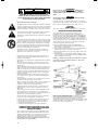 4
4
-
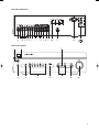 5
5
-
 6
6
-
 7
7
-
 8
8
-
 9
9
-
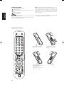 10
10
-
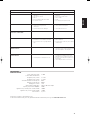 11
11
-
 12
12
-
 13
13
-
 14
14
-
 15
15
-
 16
16
-
 17
17
-
 18
18
-
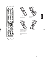 19
19
-
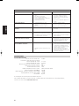 20
20
-
 21
21
-
 22
22
-
 23
23
-
 24
24
-
 25
25
-
 26
26
-
 27
27
-
 28
28
-
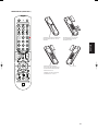 29
29
-
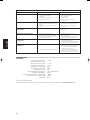 30
30
-
 31
31
-
 32
32
-
 33
33
-
 34
34
-
 35
35
-
 36
36
-
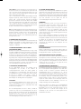 37
37
-
 38
38
-
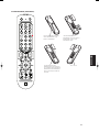 39
39
-
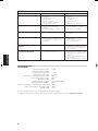 40
40
-
 41
41
-
 42
42
-
 43
43
-
 44
44
-
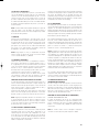 45
45
-
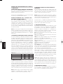 46
46
-
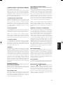 47
47
-
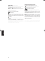 48
48
-
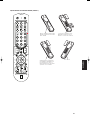 49
49
-
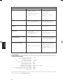 50
50
-
 51
51
-
 52
52
-
 53
53
-
 54
54
-
 55
55
-
 56
56
-
 57
57
-
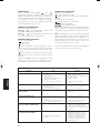 58
58
-
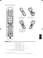 59
59
-
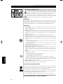 60
60
-
 61
61
-
 62
62
-
 63
63
-
 64
64
-
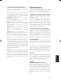 65
65
-
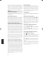 66
66
-
 67
67
-
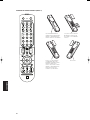 68
68
-
 69
69
-
 70
70
-
 71
71
-
 72
72
-
 73
73
-
 74
74
-
 75
75
-
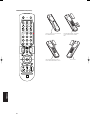 76
76
-
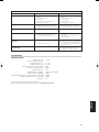 77
77
-
 78
78


NAD C 352 Manuale del proprietario
- Categoria
- Lettore CD
- Tipo
- Manuale del proprietario
in altre lingue
- français: NAD C 352 Le manuel du propriétaire
- español: NAD C 352 El manual del propietario
- Deutsch: NAD C 352 Bedienungsanleitung
- Nederlands: NAD C 352 de handleiding
- português: NAD C 352 Manual do proprietário
- svenska: NAD C 352 Bruksanvisning
