Brandt DCM390XE1 Manuale del proprietario
- Categoria
- Piani cottura
- Tipo
- Manuale del proprietario

mod.
Libretto istruzioni
Libretto istruzioni
IT
IT
Instructions booklet
Instructions booklet
GB
GB
Notice demploi et entretien
Notice demploi et entretien
FR
FR
Manual de instrucciones
Manual de instrucciones
ES
ES

INFORMAZIONI GENERALI
AVVERTENZE AMBIENTALI
Imballaggio rifiuti
Non gettate l'imballaggio del vostro apparecchio nella spazza
tura, bensì selezionate i vari materiali (ad es. lamina, cartone,
polistirolo) secondo le prescrizioni locali per lo smaltimento
rifiuti.
Questo prodotto risponde alle esigenze delle direttive comunitarie:
- 2006/95/CEE relativa alla "bassa tensione".
- 89/336/CEE relativa alla "perturbazione elettromagnetica".
- 90/396/CEE relativa agli Apparecchi a gas
- 89/109/CEE relativa ai "materiali in contatto con gli alimenti".
- Le sopra citate Direttive sono inoltre conformi alla Direttiva 93/68/CEE.
- Questo apparecchio dovrà essere destinato solo all'uso per il quale
è stato espressamente progettato, come "apparecchio per la cottura"
ad uso domestico.
- Questo apparecchio deve essere installato conformemente alle
regolamentazioni in vigore e utilizzato solo in locali ben areati.
Consultare il libretto istruzioni prima di installare e utilizzare
l' apparecchio.
GENTILE CLIENTE,
Vi invitiamo a leggere attentamente queste istruzioni prima dell'uso
e di conservarle per poterle consultare in caso di necessità.
Gli elementi dell'imballaggio (sacchetti in plastica, polistirolo espanso,
ecc.) non devono essere lasciati alla portata dei bambini in quanto
potenzialmente pericolosi.
LA GARANZIA
La Sua nuova apparecchiatura è coperta da garanzia.
Il relativo certificato di garanzia Lei lo trova qui allegato.
Se dovesse mancare lo richieda al Rivenditore indicando la data di
acquisto, il modello e il numero di matricola che sono stampigliati
sulla targhetta che identifica l'apparecchiatura (fig. A ).
Conservi la parte a Lei destinata e la esibisca in caso di necessità al
personale del Servizio di Assistenza Tecnica insieme alla ricevuta-
scontrino fiscale. Senza il rispetto di questa procedura il personale
tecnico sarà costretto ad addebitare qualsiasi eventuale riparazione.
I ricambi originali si trovano solo presso i nostri Centri di Assistenza
Tecnica e Negozi di Ricambi Autorizzati.
ASSISTENZA TECNICA
Questa apparecchiatura, prima di lasciare la fabbrica, è stata collaudata
e messa a punto da personale esperto e specializzato, in modo da
dare i migliori risultati di funzionamento.
Ogni riparazione o messa a punto che si rendesse in seguito necessaria,
deve essere fatta con la massima cura ed attenzione.
Per questo motivo raccomandiamo di rivolgerVi sempre al Conces
sionario che ha effettuato la vendita o al nostro Centro di Assistenza
più vicino specificando il tipo di inconveniente ed il modello di appa
recchiatura in Vostro possesso.
CONSIGLI ED AVVERTIMENTI DI
ORDINE GENERALE
ATTENZIONE:
- L'utilizzo di un apparecchio di cottura a gas porta alla produzione
di calore e di umidità nel locale in cui è installato. Fare in modo di
garantire una buona aerazione della cucina; mantenere aperte le
aperture di aerazione naturale o installare un dispositivo di aerazione
meccanico (cappa di aspirazione meccanica).
Un utilizzo intenso e prolungato dell'apparecchio può rendere
necessaria un' aerazione supplementare, per esempio l'apertura
di una finestra o un' aerazione più efficace, per esempio aumentando
la potenza dell' eventuale aspirazione meccanica.
- Prima dell' istallazione, verificare che le condizioni locali di
distribuzione (natura e pressione del gas) e lo stato di regolazione
dell' apparecchio siano compatibili.
Le condizioni di regolazione di questo apparecchio sono riportati
sulla targa matricola posta all' interno del cassetto inferiore dell'
apparecchio.
- Non dimenticate, prima di utilizzare l'apparecchio, di togliere le
protezioni in plastica che proteggono alcune parti (cruscotto, parti
in inox, ecc...)
- Non utilizzare l'apparecchio per riscaldare lambiente.
- Quando non si usa l'apparecchio si raccomanda di
staccare corrente
e di chiudere il rubinetto generale del gas.
- Prima di effettuare qualsiasi riparazione o intervento,
staccare
la presa della corrente e chiudere il rubinetto del gas.
IN CASO D'INCENDIO:
In caso d'incendio,
chiudere il rubinetto generale di alimentazione
gas, staccare la corrente; non gettare mai acqua sull'olio in fiamme
o che sta friggendo.
Non tenere prodotti infiammabili o bottiglie aerosol vicino
all'apparecchio, e non vaporizzare vicino ai bruciatori accesi.
PER LA SICUREZZA DEI VOSTRI BAMBINI E DI VOI STESSI
Evitare di tenere sull'apparecchio degli oggetti attrattivi per i bambini.
Tenere i bambini lontani dall'apparecchio; non dimenticate che
alcune parti dell'apparecchio o delle pentole utilizzate, diventano
molto calde e pericolose, sia durante il funzionamento che durante
il tempo necessario al raffreddamento dopo lo spegnimento.
Fare attenzione ai manici dei tegami, tenerli disposti in modo che
i bambini non rovescino le pentole.
Non indossare indumenti o accessori ampi quando i bruciatori sono
accesi; l'incendio del materiale tessile può causare serie ferite alla
persona.
Questo apparecchio non deve essere utilizzato da persone
(compresi i bambini) con capacità fisiche, mentali o sensoriali
ridotte, o mancanza di esperienza e conoscenza, a meno che
non siano sorvegliati o istruiti riguardo l'utilizzo dell'apparecchio
da parte di una persona responsabile della loro sicurezza. E'
necessario sorvegliare i bambini affinchè non giochino con
l'apparecchio.
ATTENZIONE FORNO:
Quando il forno o il grill sono in funzione, le parti accessibili
possono diventare molto calde, è opportuno tenere i bambini
lontani dall'apparecchio.
- Evitare di cuocere gli alimenti sulla base del forno.
- In caso d'utilizzo negligente nelle vicinanze delle cerniere della porta
forno, esiste il pericolo di ferirsi le mani.
- Non permettere ai bambini di sedersi o giocare con la porta forno.
Non utilizzare la porta come sgabello.
CASSETTO INFERIORE
Non inserire materiali infiammabili o utensili in plastica nel cassetto
(situato sotto la cavità forno).
Questo apparecchio è contrassegnato in conformità alla Direttiva
Europea 2002/96/EC, riguardante i rifiuti di apparecchi elettrici ed
elettronici. Assicurandosi che questo prodotto sia smaltito in modo
corretto, l'utente contribuisce a prevenire le potenziali conseguenze
negative per l'ambiente e la salute.
Il simbolo sul prodotto o sulla documentazione di
accompagnamento indica che questo prodotto non deve essere
trattato come rifiuto domestico ma deve essere consegnato presso
l'idoneo punto di raccolta per il riciclaggio di apparecchiature elettriche
ed elettroniche. Disfarsene seguendo le normative locali per lo
smaltimento dei rifiuti. Per ulteriori informazioni sul trattamento,
recupero e riciclaggio di questo prodotto, contattare l'idoneo ufficio
locale, il servizio di raccolta dei rifiuti domestici o il negozio presso
il quale il prodotto è stato acquistato.
Fig. A
2
*
IT

USO DEI BRUCIATORI A GAS
Sulla mascherina sono indicati i seguenti simboli vicino ad ogni
manopola:
- Disco pieno rubinetto chiuso
- Fiamma grande apertura massima
- Fiamma piccola apertura minima
La posizione del minimo si trova al termine della rotazione antioraria
della manopola. Tutte le posizioni di funzionamento devono essere
scelte tra le posizioni di massimo e minimo, mai tra il massimo e la
chiusura.
ACCENSIONE MANUALE
Per accendere uno dei bruciatori, avvicinare un fiammifero al bruciatore
interessato, premere la manopola corrispondente al bruciatore prescelto
e ruotarla in senso antiorario fino alla posizione di massimo.
ACCENSIONE ELETTRICA (secondo i modelli)
Per accendere uno dei bruciatori, premere la manopola corrispondente
al bruciatore prescelto e ruotarla in senso antiorario fino alla posizione
di massimo; contemporaneamente azionare il pulsante dell'accensione
elettrica posto sul cruscotto e indicato con il simbolo .
In mancanza di corrente elettrica, il bruciatore può essere acceso
anche con un fiammifero.
ACCENSIONE ELETTRICA AUTOMATICA (secondo i modelli)
Per accendere uno dei bruciatori, premere la manopola corrispondente
al bruciatore prescelto e ruotarla in senso antiorario fino alla posizione
di massimo. Mantenendo premuta la manopola si attiverà l'accensione
automatica del bruciatore.
In mancanza di corrente elettrica, il bruciatore può essere acceso
anche con un fiammifero.
APPARECCHI CON VALVOLA DI SICUREZZA
(secondo i modelli)
Per effettuare l'accensione dei bruciatori è necessario effettuare le
stesse operazioni descritte sopra. In questo caso però le manopole
una volta portate in posizione di apertura devono essere mantenute
premute per circa 10 secondi.
Qualora per un qualsiasi motivo la fiamma del bruciatore dovesse
spegnersi, la valvola di sicurezza interverrà automaticamente bloccando
il passaggio del gas al bruciatore interessato.
RISPARMIO ENERGETICO
Il diametro del fondo della pentola deve essere adeguato al diametro
del bruciatore. La fiamma del bruciatore non deve mai fuoriuscire
dal diametro della pentola.
Utilizzare pentole con fondo piatto.
Cuocere possibilmente con coperchio. Questo consente di utilizzare
potenze più basse.
Cuocere verdure, patate, ecc., con poca acqua per ridurre i tempi
di cottura.
Lapparecchio è dotato di zone di cottura di diametro e potenza
diversa. Le posizioni sono chiaramente indicate e il riscaldamento
avviene solo entro i diametri tracciati sul piano. Per avere un buon
rendimento ed un consumo denergia adeguato è indispensabile usare
solo ed esclusivamente pentole e tegami adatti. Pentole e tegami non
devono avere un fondo ruvido, onde evitare graffi sul piano di cottura
in vetroceramica. Il fondo della pentola o del tegame dovrebbe essere
pulito e asciutto prima di essere impiegato.
Il diametro del fondo della pentola o del tegame deve coincidere con
quello della zona di cottura.
Fondi di pentole e tegami, quando ancora freddi, debbono essere un
po più curvi verso linterno, giacché scaldandosi si espandono ed
Attenzione
La superficie di cottura è resistentissima. Tuttavia essa non è certo
infrangibile e potrebbe venire danneggiata specialmente da oggetti
appuntiti o duri che dovessero cadervi sopra con una certa forza.
Qualora sulla suddetta superficie di cottura vi fossero rotture,
incrinature o fessure, non utilizzatela più; mettetevi in contatto
subito con il servizio assistenza.
Queste norme sono molto importanti, se trascurate si avrà una grande
dispersione di calore e di conseguenza denergia; inoltre il calore non
assorbito dalle pentole si propaga sul piano, sulla cornice ed anche
sul mobile.
Uso del piano di cottura
Durante il primo periodo di funzionamento del piano si può avvertire
un odore acre o di bruciato che svanirà completamente dopo il ripetuto
funzionamento.
Il piano è dotato per ogni zona di cottura di un commutatore posto
sul cruscotto dellapparecchio con il quale si possono impostare
diverse gamme di temperatura. Per seguire una normale cottura,
dopo aver posto la pentola sulla posizione voluta sul piano, regolare
la manopola sulla posizione di massima potenza. Una spia sul
cruscotto segnala se la zona è in funzione o se è spenta.
Alcuni piani di cottura sono dotati di lampada spia posta anteriormente
tra le due zone di cottura, la quale si accende quando una o più zone
di riscaldamento superano la temperatura di circa 60°C.
La lampada spia si spegne solo quando la temperatura delle zone
di cottura è scesa sotto ai 60°C circa.
Trascorsi alcuni minuti per raggiungere lebollizione, regolare la
manopola su una posizione inferiore a seconda della quantità per la
continuazione della cottura in modo che la pentola non trabocchi e
non venga sprecata energia elettrica.
Importante
Usando il piano in vetroceramica, fare molta attenzione specialmente
ai bambini.
ZONE DI COTTURA CON REGOLATORE D'ENERGIA
La zona di cottura viene comandata da un regolatore d'energia.
L'attivazione del circuito avviene ruotando la manopola da 1 a 11
Fig C.
Una spia sul cruscotto oppure, secondo i modelli, sul piano segnala
se la piastra è in funzione o se è spenta.
3
2
1
5
4
6
6
5
4
3
2
1
7
8
9
10
11
Fig.B Fig.C
ZONE DI COTTURA ( secondo i modelli )
La zona di cottura viene comandata da un commutatore e l'attivazione
della stessa avviene ruotando la manopola da 1 a 6 (Fig B).
Una spia sul cruscotto oppure, secondo i modelli, sul piano segnala
se la piastra è in funzione o se è spenta.
aderiscono così al piano di cottura. In tal modo lenergia si trasmette
nel migliore dei modi. Lo spessore ottimale del fondo di pentole e
tegami è, nel caso di metallo smaltato, di 2-3 mm, per lacciaio con
fondo a sandwich di 4-6 mm.
Un semplice test è daiuto nellacquisto di pentolame da cottura. Per
vedere se il fondo di una pentola o un tegame (a freddo) è più stretto
allinterno in maniera adeguata si appoggia il centro del fondo obli
quamente ad uno spigolo del tavolo dritto; poi si tirano tra il centro
del fondo e lo spigolo del tavolo delle striscioline di carta per macchina
da scrivere. I valori adeguati sono: 5-10
striscioline di carta per il pentolame di metallo smaltato, 2-5 striscioline
di carta per il pentolame di acciaio (tanto più grande è il diametro del
fondo, tanto più numerose risultano le striscioline).
3
Bruciatori pentole
Ø min. Ø max
RAPIDO 180 mm 220 mm
SEMIRAPIDO 120 mm 200 mm
AUSILIARIO 80 mm 160 mm
TRIPLA C. 220 mm 260 mm
USO DEL PIANO DI LAVORO
PIANO DI COTTURA IN VETROCERAMICA
IT

Tabelle di cottura ad aria calda
1 FORNI A CONVEZIONE NATURALE (forno piccolo)
Il forno è dotato di:
una resistenza suola;
una resistenza cielo.
Ruotando in senso orario la manopola del termostato (fig. D1) è
possibile selezionare la temperatura desiderata nel forno e, secondo
i modelli, una o più funzioni:
Forno spento
Luce forno
60 ÷ max Inserimento della resistenza superiore + inferiore
Inserimento della resistenza inferiore
Inserimento della resistenza superiore
Inserimento del grill (girarrosto optional )
0 Spento
1 Tenue
2 Dolce
3 Lento
4 Medio
5 Forte
6 Vivo
Per sciogliere burro, cioccolato, ecc.
Per scaldare piccole quantità di liquido.
Per scaldare maggiori quantità di liquido.
Per preparare creme e salse a lunga cottura.
Per disgelare alimenti surgelati e preparare stufati,
cuocere alle temperature di ebollizione, per arrosti di
carni delicate e pesce.
Per cuocere alimenti che debbono essere portati
all'ebollizione, per arrosti di carni dedicate e pesce.
Per arrosti di cotolette e bistecche, per grandi lessi.
Per portare all'ebolizione grandi quantità d'acqua, per
friggere
Pos. Intensità Cotture effettuabili
Calore
0
1 - 2
3 - 4
5 - 6
7 - 8
9 - 10
11
TABELLA DI GUIDA
A titolo indicativo vi indichiamo le posizioni di cottura che dipendono
dalla quantità e qualità del cibo.
6
5
4
3
2
1
7
8
9
10
11
Fig.D
ZONE DI COTTURA CON REGOLATORE D'ENERGIA A DOPPIO
CIRCUITO
La zona di cottura viene comandata da un regolatore d'energia.
1) L'attivazione del primo circuito avviene ruotando la manopola da
1 a 11 (Fig D).
2) L'attivazione del secondo circuito avviene ruotando la manopola
oltre il numero 11.
Per ritornare al funzionamento ad un solo circuito, riportare la manopola
a zero e riposizionarla sul numero desiderato.
Una spia sul cruscotto oppure, secondo i modelli, sul piano segnala
se la piastra è in funzione o se è spenta.
Il diametro del fondo della pentola deve essere uguale al diametro
della piastra di cottura, oppure leggermente superiore.
Non deve comunque mai essere inferiore.
Utilizzare pentole con fondo piatto.
Alla prima accensione del forno può svilupparsi fumo di odore acre,
causato dal primo riscaldamento del collante dei pannelli disolamento
avvolgenti il forno (è opportuno riscaldarlo alla massima tempera
tura per una durata di 30-40 minuti a porta chiusa). Si tratta di un
fenomeno assolutamente normale e, in caso si verificasse, occorre
attendere la cessazione del fumo prima di introdurre le vivande.
Il forno è generalmente corredato di: griglia per la cottura dei cibi
riposti in teglie o appoggiate direttamente sulla griglia, leccarda per
la cottura di dolci, biscotti, o per raccogliere i sughi ed i grassi di cibi
riposti direttamente sulla griglia.
Nota: nelle seguenti tabelle sono riportate le indicazioni più importanti
per la cottura di alcuni dei principali piatti. I tempi di cottura consigliati
in queste tabelle sono indicativi. Siamo certi che dopo poche prove
potrete apportare quelle modifiche necessarie per ottenere i risultati
desiderati.
ATTENZIONE :
In alcuni modelli, per evitare il surriscaldamento delle manopole, è
obbligatorio montare l'apposita protezione S (fig. 3) fornita in dotazione
con la cucina e posizionare la porta semiaperta (fig. 3A).
Preparazione Temp. °C. Minuti
Pesce 180-240 sec. dimensioni
Carne
Arrosto di bue 250 30 per kg.
Arrosto di vitello 200-220 60 per kg.
Pollo 200-240 50 circa
Anatra od oca 220 sec. peso
Cosciotto di montone 250 30 per kg.
Arrosto di maiale 250 60 per kg.
Soufflets 200 60 per kg.
Dolci (Pasticceria)
Panfrutto 160 50-60
Savoiardi 160 30-50
Pasta frolla 200 15
Pasta sfoglia 250 15
Torta di frutta 200-220 30
Meringhe 100 60
Sformato 220 30
4 quarti 120-140 60
Brioches 160-180 45
Preparazione Temp. °C. Minuti Peso kg.
Primi piatti
Lasagne al forno 200-220 20-25 0,5
Pasta al forno 200-220 25-30 0,5
Riso alla Creola 200-230 20-25 0,5
Pizza 210-230 30-45 0,5
Carne
Arrosto di vitello 160-180 65-90 1-1,2
Arrosto di maiale 160-170 70-100 1-1,2
Arrosto di bue 170-190 40-60 1-1,2
Arrosto di manzo 170-180 65-90 1-1,2
Roast-Beef 180-190 40-45 1-1,5
Arrosto di agnello 140-160 100-130 1,5
Pollo arrosto 180 70-90 1-1,2
Anitra arrosto 170-180 100-160 1,5-2
Oca arrosto 160-180 120-160 3-3,5
Tacchino arrosto 160-170 160-240 5 ca.
Coniglio arrosto 160-170 80-100 2 ca.
Lepre arrosto 170-180 30-50 2 ca.
Pesci 160-180 sec. peso
Dolci (Pasticceria)
Torta di frutta 180-200 40-50
Ciambella 160-180 35-45
Torta Margherita 200-220 40-45
Pan di Spagna 200-230 25-35
Schiacciata duva 230-250 30-40
Brioches 170-180 40-60
Strûdel 160 25-35
Sfogliatine dolci 180-200 20-30
Frittelle di mele 180-200 18-25
Budino di savoiardi 170-180 30-40
Biscotti di Savoia 150-180 50-60
Toast 230-250 7
Pane 200-220 40
4
USO DEL FORNO ELETTRICO
Tabelle di cottura sistema tradizionale
IT

Ruotata la manopola di comando su questa posizione, la lampada
resta accesa per tutte le operazioni che seguono.
Scongelamento con ventilatore
Questa posizione permette di far circolare laria a temperatura ambiente
intorno al cibo surgelato facendolo così scongelare senza modificare
od alterare il contenuto proteico.
Convezione naturale
Sono in funzione la resistenza suola e la resistenza cielo forno. È la
cottura tradizionale, ottima per arrostire cosciotti, selvaggina, ideale
per biscotti, mele al forno e per rendere i cibi molto croccanti. Si
ottengono buoni risultati per cotture su un ripiano con regolazione
della temperatura da 50 a MAX°C.
Forno ventilato
Sono in funzione il ventilatore e la resistenza circolare. Laria calda
regolabile da 50 a MAX°C viene uniformemente ripartita sui diversi
ripiani; è ideale per cuocere contemporaneamente diversi tipi di cibo
(carne, pesce) senza miscelare sapori e odori. Cottura delicata indicata
per pan di Spagna, torte Margherita, pasta sfoglia, ecc.
Inserimento grill medio
In questa posizione viene inserita la resistenza del grill medio a raggi
infrarossi. Serve per grigliare o gratinare piatti tradizionali di dimensioni
piccole. Questa funzione può essere usata tra 50 e MAX°C.
ATTENZIONE:
La temperatura indicata sul cruscotto corrisponderà con la temperatura
mantenuta nel centro del forno solo quando le funzioni selezionate
sono oppure .
2 FORNO MULTIFUNZIONE (forno grande)
Il forno è dotato di:
una resistenza suola;
una resistenza cielo;
una resistenza circolare che avvolge il ventilatore.
N.B.: Linserimento di qualsiasi funzione avviene sempre dopo aver
posizionato la manopola del termostato in corrispondenza di una
temperatura desiderata.
Manopola termostato forno (fig. E)
Ruotando in senso orario questa manopola si può ottenere una tempe
ratura del forno compresa tra 50 e MAX°C.
Manopola commutatore forno (fig. F)
Ruotando in senso orario la manopola del commutatore, è possibile
selezionare una delle seguenti funzioni che qui di seguito riportiamo.
Utilizzazione del forno con termostato e commutatore separati.
Il forno deve sempre essere usato con la porta chiusa.
Quando si utilizzano le funzioni posizionare la manopola
del termostato tra 180 ÷ 200°C come massima temperatura.
Nota:
Per tutte le operazioni descritte al punto 1 e 2, si determina linse
rimento dellilluminazione interna del forno.
Una spia posta sul cruscotto rimane accesa finché la temperatura
non è stata raggiunta, in seguito si accenderà ad intermittenza.
Questa funzione deve essere utilizzata con la griglia porta piatto al
terzo gradino partendo dal basso del forno a 12 cm circa dalla superficie
e con la porta chiusa. Lutilizzatore potrà cambiare i gradini, a seconda
dei suoi gusti personali ed a seconda delle diverse necessità dei cibi.
Prima di infornare, lasciare riscaldare per 5 minuti.
Per il funzionamento del girarrosto, ripetere le operazioni descritte nel
paragrafo 1 di pagina 4 posizione .
Uso del girarrosto
- Infilare il pollo o la parte da arrostire nello spiedo L avendo cura
dimmobilizzarlo tra le due forchette F e di equilibrarlo, in modo da
evitare sforzi inutili al motoriduttore R (fig. 2).
- Mettere lo spiedo sul supporto G, dopo aver introdotto la sua
estremità opposta nel foro P del motorino R (fig. 2).
- Mettere la leccarda con un po dacqua sotto lo spiedo.
Fig.D1
50
75
100
125
150
175
200
225
max
Fig.E Fig.F
Inserimento grill totale
In questa posizione viene inserita la resistenza del grill a raggi infrarossi.
Serve per grigliare o gratinare piatti tradizionali. La porta forno deve
essere chiusa e il termostato va messo tra 180÷200°C.
Grill totale ventilato
Laria, riscaldata dalla resistenza grill, viene aspirata dal ventilatore
che la riversa sulle vivande. Il grill ventilato sostituisce egregiamente
il girarrosto e garantisce ottimi risultati con pollame, salsicce e carni
rosse, anche in quantità rilevante. Il termostato va messo tra
180÷200°C.
Resistenza suola ventilata
Laria, riscaldata dalla resistenza suola, viene aspirata dal ventilatore
che la riversa sulle vivande. Questa funzione può essere utilizzata
per sterilizzare vivande. Questa funzione può essere usata tra 50 e
MAX°C.
- Per togliere lo spiedo, operare in modo contrario utilizzando la
manopola A ed un guanto di protezione in lana isolante (fig 2).
ATTENZIONE :
In alcuni modelli, per evitare il surriscaldamento delle manopole, è
obbligatorio montare l'apposita protezione S (fig. 3) fornita in dotazione
con la cucina e posizionare la porta semiaperta (fig. 3A).
Fig. 3
Fig. 2
Fig. 3A
1
A
L
F
R
P
G
2
1
S
5
60
max
200
170
130
90
USO DEL GRILL
GIRARROSTO ( secondo i modelli )
IT

OROLOGIO LED (Fig. 4)
Caratteristiche
Orologio 24 ore con programma automatico e contaminuti.
Funzioni
Durata cottura, fine cottura, posizione manuale, orologio, contaminuti,
tempi impostabili fino a 23 ore 59 minuti.
Visualizzazione
Display fluorescente a 4 cifre di 7 segmenti per lindicazione dellora
e dei tempi di cottura.
Durata cottura o funzione manuale = simbolo pentola
Funzione automatica = AUTO
Contaminuti = simbolo campana
A seconda delle funzioni prescelte si illumina il simbolo corrispondente.
Programmazione
La programmazione avviene premendo il tasto della funzione desiderata
e dopo averlo rilasciato è sufficiente che entro 5 secondi si inizi ad
impostare il tempo con i tasti + e -.
Tasto + e -
Azionando i tasti + e - il tempo aumenta o decresce ad una velocità
variabile a seconda della durata di pressione esercitata sul tasto.
Impostazione dellora
Premendo contemporaneamente due tasti manual ed il tasto + o -,
si imposta lora desiderata. Con tale operazione vengono cancellati
eventuali programmi precedentemente impostati, i contatti sono
disinseriti ed il simbolo AUTO lampeggia.
Funzionamento manuale
Azionare il tasto manuale, i contatti del relais sono inseriti, il simbolo
AUTO si spegne, il simbolo pentola si illumina. Il funzionamento
manuale può avvenire soltanto al termine della programmazione
automatica o dopo averla cancellata.
Funzionamento automatico
Azionando il tasto di durata o fine cottura il programmatore si commuta
automaticamente dalla funzione manuale a quella automatica.
Funzionamento semiautomatico con durata cottura
Premere il tasto durata cottura ed impostare il tempo desiderato con
il tasto + o -. Il simbolo AUTO si illumina in permanenza ed altrettanto
il simbolo di durata cottura. Il relais si inserisce immediatamente.
Quando il tempo di fine cottura coincide con lora, il relais ed il simbolo
di durata cottura si disinseriscono, si mette in funzione il segnale
acustico ed il simbolo AUTO lampeggia.
Funzionamento semiautomatico con fine cottura
Premere il tasto di fine cottura. Verrà visualizzata sul display lora del
momento. Selezionare il tempo di fine cottura desiderato con il tasto
+. I simboli AUTO e durata cottura si illuminano in permanenza. I
contatti del relais si inseriscono.
Quando il tempo di fine cottura coincide con lora, il relais ed il simbolo
di durata cottura si disinseriscono. Allo scadere del tempo
di cottura il simbolo AUTO lampeggia, si mette in funzione il segnale
acustico e sia il simbolo di durata sia il relais si spengono.
Funzionamento automatico con durata e fine cottura
Premere il tasto di durata e selezionare la durata cottura desiderata
con il tasto + o -. I simboli AUTO e durata si illuminano in permanenza.
Il relais si inserisce. Premere il tasto di fine cottura. Sul display compare
ISTRUZIONI PER LUSO DEI DISPOSITIVI DI CONTROLLO
(SECONDO I MODELLI)
Fig. 6
CONTAMINUTI (Fig.5)
Per ottenere il tempo di cottura desiderato ruotare la manopola in
senso orario.
Il contaminuti può essere regolato da 1 a 60 min. Allo scadere del
tempo fissato un segnale acustico avvertirà della fine cottura.
OROLOGIO TEMPORIZZATORE ELETTRONICO PER
CUCINA (Fig.7)
2. Funzioni
Acceso Il display lampeggia.
Regolazione dellorario
Premere il pulsante di sinistra.
Inserire lorario con i pulsanti + e -.
Questa funzione resta attivata per 7 secondi dopo lultima operazione
+ / -.
Regolazione del temporizzatore
Questa funzione è permanentemente attivata e sarà immediatamente
regolata con i pulsanti + / -.
Durante la regolazione le unità sono 10 secondi.
PROGRAMMATORE FINE COTTURA (Fig.6)
Per operare in modo manuale ruotare la manopola in senso antiorario
e portarla in corrispondenza dell'indice ; per programmare la durata
della cottura, ruotare invece in senso orario e dare un tempo di cottura
con l'apposita manopola (max.120 min.).
A cottura ultimata il forno viene automaticamente disinserito.
il tempo di fine cottura più prossimo. Selezionare il tempo di fine
cottura desiderato mediante il tasto +. Il relais ed il simbolo di durata
si disinseriscono. Il simbolo si illumina di nuovo quando lora coincide
con il tempo di inizio cottura. Allo scadere del tempo di cottura il
simbolo AUTO lampeggia. Si mette in funzione il segnale acustico e
sia il simbolo di durata che il relais si spengono.
Contaminuti
Premere il tasto contaminuti e selezionare il tempo di cottura desiderato
mediante il tasto + o -.
Durante il funzionamento del contaminuti si illumina il simbolo campana.
Al termine del tempo impostato si mette in funzione il segnale acustico
ed il simbolo campana si spegne.
Segnale acustico
Il segnale acustico si mette in funzione al termine di una programma
zione o della funzione contaminuti ed ha una durata di 15 minuti. Per
interromperlo prima, si dovrà premere uno qualsiasi dei tasti delle
funzioni.
Inizio programma e controllo
Il programma ha inizio circa 4 secondi dallimpostazione. In qualsiasi
momento è possibile controllare il programma impostato premendo
il tasto corrispondente.
Errore di programmazione
Si ha un errore di programmazione se lora indicata dallorologio è
compresa tra lora di inizio cottura e lora di fine cottura. Lerrore
dimpostazione può essere corretto variando la durata o il tempo di
fine cottura, in presenza di un errore di impostazione i relais sono
disinseriti.
Annullamento di un programma
Si può cancellare un programma premendo il tasto di durata cottura
e di seguito il tasto - fino a che sul display non comparirà lindicazione
00 00. Al termine di un programma impostato, questo si cancella
automaticamente.
0
80
70
90
100
110
120
stop
60
50
40
30
20
10
Fig. 5
Fig. 4
Lapparecchio, secondo i modelli può essere dotato di uno dei seguenti
timer.
6
Contaminuti
Tempo di cottura
Fine cottura
Manuale
Togliere tempo
Aggiungere tempo
A
U
T
O
10
5
15
20
25
30
35
40
45
50
55
IT

Fig. 7
1 Orario del giorno
2 Temporizzazione ed inserimento
3 Temporizzazione ed inserimento
segnale
Prima di procedere alla pulizia, chiudere il rubinetto dell'impianto
gas generale e staccare la spina dalla presa di corrente o togliere
la corrente della linea di alimentazione a mezzo dell'interruttore
generale dell'impianto elettrico.
Evitare di pulire le superfici dell'apparecchio quando le stesse
sono ancora calde.
NOTA: non deve essere usato il vapore per la pulizia del forno.
IMPORTANTE
Verificare periodicamente il buono stato del tubo di collegamento
esterno del gas e sostituirlo non appena presenta qualche
anomalia. Non si commetta l'errore di farlo riparare.
SUPERFICI SMALTATE
Pulire con una spugna inumidita in acqua e sapone.
Le macchie di grasso possono essere tolte facilmente con acqua
calda o con un prodotto specifico, reperibile in commercio per la pulizia
dello smalto. Evitare i prodotti contenenti sostanze abrasive. Evitare
di lasciare sullo smalto sostanze acide o alcaline (succo di limone,
aceto, sale, ecc.). Gli apparecchi in acciaio inox devono essere puliti
con appositi detergenti per superfici in acciaio inox. Questi detergenti
vanno applicati con un panno morbido.
GRIGLIE E BRUCIATORI
Per procedere alla pulizia dei bruciatori del piano di lavoro, occorre
estrarli dalla loro sede sfilandoli verso l'alto, e metterli per una decina
di minuti in una soluzione di acqua calda con l'aggiunta di detersivo
non abrasivo. Dopo aver pulito e lavato i bruciatori, asciugarli accura
tamente.
Controllare sempre che nessuna delle aperture dei bruciatori sia
otturata. Consigliamo di eseguire questa operazione almeno una
volta alla settimana o ogni qualvolta se ne presenti la necessità.
Si raccomanda di rimontare i bruciatori in modo corretto.
MANUTENZIONE E PULIZIA
SUPERFICIE IN VETRO-CERAMICA
Per la pulizia del piano si possono adottare gli stessi accorgimenti
per pulire i vetri di casa vostra. Le macchie o striature chiare dovute
al fondo di alluminio delle pentole si possono togliere con aceto. Fare
attenzione a non far cadere lo zucchero sul piano durante la cottura,
nel caso dovesse cadere disinserire la piastra relativa e pulire con
acqua calda appena possibile, prima che si raffreddi. Nel caso in cui
rimanessero, dopo la cottura, residui bruciati di zucchero o simili,
questi devono essere rimossi con una spatola oppure con una lama
da barba, prima che la zona di cottura si raffreddi (vedi figura 8).
Fig. 8
Fig. 8B
Durante il conto alla rovescia il temporizzatore ha priorità sul display.
Le unità sono secondi. Il tempo massimo è di 99 minuti.
Il contatto di controllo (dove disponibile) è chiuso solo durante il conto
alla rovescia.
Ripristino del temporizzatore. Premere il pulsante + e - assieme
e rilasciare il pulsante + per primo.
Segnale
Il segnale quando è terminato il tempo rimarrà per 7 minuti se non è
ripristinato col pulsante + (un solo tocco).
Frequenza segnale
Quando il display mostra lorario del giorno, la frequenza del segnale
può essere selezionata premendo il pulsante -.
Si possono selezionare 3 diverse frequenze.
Fig. 8 A
Attenzione: non usare per la pulizia materiali ruvidi abrasivi o
raschietti metallici affilati per pulire le porte di vetro del forno
dato che possono graffiare la superficie e causare la
frantumazione del vetro.
PORTA FORNO
In alcuni modelli, la porta forno può essere smontata nel modo
seguente: le cerniere A sono provviste a tale scopo di cavallotti mobili
B che agganciati ai settori delle cerniere C, quando la porta è com
pletamente aperta, le bloccano (figura. 8B).
Rimuovere il vetro interno come illustrato in fig. 8A (operazione prevista
solo in alcuni modelli).
Fatto questo si solleva la portina verso l'esterno compiendo quindi i
due movimenti illustrati dalla figura. Per compiere queste operazioni
fate presa sui fianchi della porta in prossimità delle cerniere.
Per rimontare la portina infilate le cerniere nelle loro apposite sedi.
Prima di chiudere la portina non dimenticate di togliere i cavallotti
mobili B (fig. 8B).
Attenzione alle cerniere della porta forno esiste il pericolo di ferirsi le
mani.
FORNO
Per le parti smaltate pulire con una spugna inumidita in acqua e
sapone. Le macchie di grasso possono essere tolte facilmente con
acqua calda o con un prodotto specifico, reperibile in commercio per
la pulizia dello smalto. Evitare i prodotti contenenti sostanze abrasive.
7
A
BC
PULIZIA DEL VETRO INTERNO DELLA PORTA FORNO.
In alcuni modelli, il vetro interno della porta forno può essere rimosso:
aprire la porta in posizione semi aperta e usando le due mani, rimuovere
il vetro come illustrato in figura 8A.
Dopo la pulizia rimontare il vetro correttamente eseguendo le operazioni
inverse.
IT

REG. MAX
50mm
Fig. 9
min.100 mm
min. 50 mm
min. 650 mm
min. 400 mm
"0" mm "0" mm
min. 50 mm
OK NO
8
ISTRUZIONI DESTINATE ALLINSTALLATORE
AVVERTENZE
Prima di effettuare qualsiasi riparazione o intervento,
staccare la
presa della corrente e chiudere il rubinetto del gas.
Il tecnico qualificato è responsabile della corretta installazione
secondo le norme di sicurezza vigenti.
Il costruttore declina ogni responsabilità per eventuali danni a persone,
animali o cose derivanti dalla mancata osservanza delle norme sopra
indicate. Non usare limpugnatura della maniglia porta forno per
operazioni di movimentazione, compresa quella necessaria per togliere
lapparecchiatura dallimballo.
Lapparecchio è in classe 1 oppure classe 2 sotto-classe 1.
IMPORTANTE: Il rivestimento del mobile deve essere di materiale
resistente al calore (minimo 85°C).
Se l'apparecchio deve essere installato vicino ai mobili, lasciare gli
spazi minimi previsti dal disegno seguente (fig. 9).
APPARECCHI A GAS
Questo apparecchio non è collegato ad un dispositivo di scarico dei
prodotti della combustione. Deve quindi essere installato e collegato
conformemente alle norme di installazione vigenti. Particolare attenzione
sarà data alle norme applicabili in materia di aerazione del locale.
VENTILAZIONE DEI LOCALI (UNI-CIG 7129-7131)
Ricordiamo che questo apparecchio può essere installato e funzionare
solo in locali ben ventilati, secondo le norme in vigore, tali da permettere,
con aperture su pareti esterne o con appositi condotti, una corretta
ventilazione naturale o forzata che assicuri in modo permanente e
sufficiente sia l'immissione dell'aria necessaria ad una corretta
combustione sia l'evacuazione dell'aria viziata.
In particolare nel caso in cui nell'ambiente esista solo questo appa
recchio a gas, occorrerà avere una cappa sopra l'apparecchio tale da
assicurare l'evacuazione naturale e diretta dell'aria viziata, con un
condotto verticale rettilineo di lunghezza uguale ad almeno due volte
il diametro ed una sezione minima di almeno 100cm
2
.
Per l'indispensabile immissione di aria fresca nell'ambiente occorrerà
prevedere un'analoga apertura di almeno 100 cm
2
che dia direttamente
verso l'esterno, situata ad una quota prossima al livello del pavimento
in modo da non venire ostruita sia all'interno che all'esterno della
parete e da non provocare disturbi alla corretta combustione dei
bruciatori ed alla regolare evacuazione dell'aria viziata e con una
differenza di altezza rispetto all'apertura di uscita di almeno 180 cm.
Si ricorda che la quantità d'aria necessaria alla combustione non deve
essere minore a 2m
3
/h per ogni kW di potenza vedi fig. A ).
In tutti gli altri casi, quando cioè esistano nello stesso ambiente altri
apparecchi a gas, oppure quando non sia possibile avere una venti
lazione naturale diretta ed occorra invece realizzare una ventilazione
naturale indiretta od una ventilazione forzata è necessario rivolgersi
ad uno specialista qualificato in modo che provveda all'installazione
ed alla realizzazione eventuale dell'impianto di ventilazione
nell'osservanza scrupolosa delle precauzioni contenute nelle norme
in vigore.
Il posizionamento delle aperture deve essere tale che non risulti alcuna
corrente d'aria insopportabile per gli occupanti, inoltre per lo scarico
dei prodotti della combustione è vietato servirsi di canne fumarie già
utilizzate da altri apparecchi.
Nota: Quando l'apparecchio non è provvisto di sicurezza sui
bruciatori del piano di lavoro (termocoppie), le aperture di
ventilazione devono essere maggiorate nella misura del 100%
con un minimo di 200 cm
2
in conformità al D.M.21 Aprile 1993.
DIMENSIONI DINGOMBRO
a725b
60
a = 25 mm (mod. 192 - 108 YA)
x = 895 ( mod. 192 - 108)
a = 40 mm (mod.192 - 108 RC-CH)
b = 115 mm
b= piedi regolabili in altezza (90 / 140) - (115 / 165) mm
(solo in alcuni modelli).
x = 1000 ( mod. 108)
X
mod. 10
8
(h = 900)
1000
La cucina è dotata di 4 piedini (vedi fig. 9A o 10).
In alcuni modelli, i piedi sono regolabili in altezza 10 A - B.
Fig. 9A
Fig. 10
Fig. 10 A
Sollevare la cucina e avvitare i quattro piedini nelle apposite filettature
presenti negli angoli sotto lapparecchio .
Fig. 10 B
IT
min. 180 cm.
min. 100cm
2
.
min. 180 cm.
min. 100cm
2
.min. 100cm
2
.
elettroventilatore
VENTILAZIONE LOCALI
600
h
960
REG. MAX
15mm

COLLEGAMENTI GAS (UNI-CIG 7129-7131)
min. 20mm
min.100 mm
min. 50 mm min. 50 mm
min. 650 mm
min. 400 mm
min. 20mm
P
P
PORTAGOMMA
PER GAS
LIQUIDO
PORTAGOMMA
PER GAS
METANO
F
9
ATTENZIONE:
Per il collegamento tipo 3, se l' apparecchio deve essere istallato
vicino ai mobili, è necessario
lasciare gli spazi minimi previsti dal
disegno seguente (fig. 11B) oppure, se l'apparecchio deve essere
installato a contatto con i mobili come in figura 9, per il collegamento
al gas, è necessario richiedere al nostro centro assistenza
l' apposito accessorio P (vedi fig. 11C) da montare direttamente al
gomito della rampa.
Fig. 11C
F
Fig. 11
3) mediante l'inserimento di un tubo di gomma conforme alle
norme UNI-CIG 7140. Tale tubo va innestato direttamente sul
portagomma, relativo al gas utilizzato, e bloccato con una
fascetta (F) conforme alle norme UNI-CIG 7141 (fig. 11A).
In questo caso controllare la data di scadenza del tubo stampi
gliata e sostituirlo prima di tale data.
Si raccomanda di controllare che l'apparecchio sia predisposto per
il tipo di gas distribuito. Il collegamento alla tubazione del gas deve
essere effettuato a regola d'arte nonché conformemente alle normative
in vigore che prescrivono l'installazione di un rubinetto di sicurezza
all'estremità della tubazione. Per il butano ed il propano, un riduttore
di pressione conforme alle norme UNI-CIG 7432 può assolvere a
questa funzione. Le guarnizioni di tenuta devono essere conformi alle
norme UNI-CIG 9264.
Terminate le operazioni di collegamento gas, controllare la tenuta dei
raccordi con acqua e sapone.
I possibili collegamenti sono:
1) mediante tubo rigido in ferro o rame (vedi fig. 11).
2) mediante tubo flessibile in acciaio inossidabile a parete continua
con attacco meccanico conforme alle norme UNI-CIG 9891 (massima
lunghezza del tubo esteso 2.000 mm) vedi fig. 11.
AVVERTENZE
Si ricorda per i tubi flessibili in gomma di:
1 - evitare strozzature o schiacciamenti del tubo
2 - non essere soggetti a sforzi di trazione e di torsione
3 - evitare contatti con corpi taglienti, spigoli vivi, ecc...
4 - non porli a contatto con parti che raggiungono temperature maggiori
di 70°C oltre a quella ambiente.
5 - renderli ispezionabili lungo tutto il loro percorso.
Le cucine, secondo i modelli, possono essere predisposte per
l'alimentazione gas come descritto sotto al pargrafo A e B.
A) Cucina predisposta per lalimentazione sia a destra o a
sinistra.
Per effettuare lo spostamento dell' alimentazione è sufficiente
invertire la posizione del tappo di chiusura e del raccordo
(fig.12).
Ad operazione ultimata accertarsi che non vi siano perdite di
gas.
Nota: nel caso sia necessario collegare la cucina dalla parte
opposta, bisogna far passare il tubo flessibile nei supporti
di guida A come indicato nella figura (12 B)
Fig. 12 A
B) Cucina predisposta per lalimentazione a sinistra (fig.12 A).
Fig. 12 B
A
TAPPO DI CHIUSURA
Fig. 12
IT
F
F
PORTAGOMMA
PER GAS
METANO
PORTAGOMMA
PER GAS
LIQUIDO
Fig. 11A
Fig. 11B

Tipo di apparecchio Alimentazione monofase 230 V~
Tipo cavo Sezione
Piano gas con doppio forno elettrico
3 x 2,5 mm
2
Piano ceram. con doppio forno elettrico
*
3 x 6 mm
2
Gomma H05 RR-F
oppure
Gomma H05 RN-F
*
TENENDO CONTO DEL FATTORE DI CONTEMPORANEITA' DI 0,59
Tipo di apparecchio Alimentazione bifase 400 V~
Tipo cavo Sezione
Piano ceram. con doppio forno elettrico 4 x 4 mm
2
Tipo di apparecchio Alimentazione trifase 400 V~
Tipo cavo Sezione
Piano ceram. con doppio forno elettrico 5 x 2,5 mm
2
Gomma H05 RR-F
oppure
Gomma H05 RN-F
Gomma H05 RR-F
oppure
Gomma H05 RN-F
COLLEGAMENTO ELETTRICO
10
L'allacciamento dell'apparecchio alla rete elettrica deve essere
effettuato da personale specializzato a conoscenza delle norme di
sicurezza vigenti.
La messa a terra dell'apparecchio è obbligatoria a termine di
legge. Prima di effettuare il collegamento elettrico, assicurarsi
dell'efficienza della messa a terra.
Accertarsi che la valvola limitatrice e l'impianto domestico possano
sopportare il carico dell'apparecchiatura.
Se un apparecchio fisso non è provvisto di cavo di alimentazione e
di spina, deve essere previsto nella rete di alimentazione un dispositivo
di disconnessione con una distanza di apertura dei contatti che
consenta la disconnessione completa nelle condizioni della categoria
di sovratensione III, conformemente alle regole di installazione.
Il cavo di terra giallo/verde non deve essere interrotto dall'inter-
ruttore.
Importante: i fili del cavo hanno i seguenti colori:
- giallo/verde = per la messa a terra " " (E)
- blu = per il neutro "N"
- marrone = per la fase "L"
- Il cavo elettrico non deve essere a contatto con parti con temperature
maggiori di 50°C oltre a quella ambiente.
- Se si usa una spina per il collegamento, la spina da collegare al
cavo di alimentazione e la presa al quale viene collegato dovranno
essere dello stesso tipo (conformi alle norme).
Se l'apparecchiatura risulta predisposta per un diverso tipo di gas da
quello di alimentazione disponibile, si devono cambiare gli iniettori,
regolare la portata minima, cambiare portagomma.
Per cambiare gli iniettori del piano di lavoro, è necessario effettuare
le seguenti operazioni: togliere le griglie; togliere i bruciatori, gli
spartifiamma (vedi fig.14 A); cambiare l'iniettore (vedi figura 14 B) e
sostituirlo con quello adatto al nuovo tipo di gas (vedi tab.D). Rimontare
il tutto in senso inverso facendo attenzione a collocare lo spartifiamma
in modo coretto sul bruciatore.
Fig. 14
Tipo di cavo dalimentazione
TIPO DI ALIMENTAZIONE
E' possibile ottenere diversi collegamenti con il semplice spostamento dei cavallotti
sulla morsettiera.
400 V 3N~
5
4
3
2
1
L1
L2
L3
N
E
400 V
2
N~
5
4
3
2
1
L1
L2
N
E
230
V ~
5
4
3
2
1
L1
N
E
PIANO VETROCERAMICO
piastre Ø mm Watt
F 145 1200
G - I 180 1800
H 210 2200
L 265 1400/2200
G
H
F
I
L
Fig. 15 Fig. 16
PORTATA MINIMA DEI RUBINETTI PIANO
Per regolare la portata minima procedere come segue:
- Accendere il bruciatore e girare la manopola verso la posizione di
portata minima ; togliere la manopola del rubinetto. Inserire un
cacciavite piccolo nell'asta del rubinetto (fig. 15).
Attenzione: nei rubinetti valvolati la vite di regolazione Z del minimo
si trova all'esterno dell'asta del rubinetto (fig. 16).
SOSTITUZIONE DEL CAVO
In caso di danneggiamento del cavo, provvedere alla sua sostituzone
secondo le seguenti istruzioni:
- aprire la scatola ella morsettiera come descritto in figura qui sotto;
- svitare la vite A che blocca il cavo;
- sostituire il cavo con uno di lunghezza uguale e corrispondente
alle caratteristiche descritte in ta
bella;
- il conduttore di terra giallo-verde
deve essere collegato al morsetto
e deve essere più lungo di
circa 10 mm rispetto ai conduttori
di linea;
- il conduttore neutro blu deve es
sere collegato al morsetto con
traddistinto con la lettera N;
- il conduttore di linea va collegato
al morsetto contraddistinto con la
lettera L.
IT
REGOLAZIONI GAS
AB
Valori riferiti al Hs - 15°C - 1013,25mbar.
TAB. D
Cat. II 2H3+
TABELLA GENERALE INIETTORI
Tipo di gas mbar Ugello Bruciatori Potenza KW Consumo
N° max. min. max. min.
115 Rapido 3,00 0,75 286 l/h 72 l/h reg.
METANO 20 97 Semi rapido 1,75 0,48 167 l/h 46 l/h reg.
G 20 72 Ausiliario 1,00 0,33 95 l/h 31 l/h reg.
128 Tripla corona 3,30 1,30 315 l/h 124 l/h reg.
128 Pescera 2,90 1,50 277 l/h 143 l/h reg.
BUTANO 28-30 85 Rapido 3,00 0,75 219 g/h 55 g/h 42
G 30 65 Semi rapido 1,75 0,48 128 g/h 35 g/h 31
50 Ausiliario 1,00 0,33 73 g/h 24 g/h 27
PROPANO 37 93 Tripla corona 3,30 1,30 241 g/h 95 g/h 60
G 31 85 Pescera 2,90 1,50 211 g/h 109 g/h 65
N°
By pass
Z

E 14
25 W - 230 V~
T300°C
A
A
11
Fig. 19
Fig. 18
15
7
D
V
Pulire il cono ed il suo alloggiamento con uno straccio imbevuto di
diluente. Ingrassare il cono con l'apposito grasso, rimetterlo nella sua
sede e ruotarlo alcune volte. Togliere nuovamente il cono e togliere
il grasso superfluo assicurandosi che i passaggi del gas non siano
otturati da residui di grasso. Rimontare il tutto accuratamente in senso
inverso.
Terminate le operazioni controllare la tenuta dei raccordi con acqua
e sapone.
SOSTITUZIONE RUBINETTI
Aprire il piano di lavoro e smontare anche il cruscotto come descritto
nel paragrafo precedente. Svitare il dado D del tubetto che porta gas
al bruciatore, svitare la vite V che fissa il rubinetto alla briglia ed estrarre
quest'ultimo (vedi figura 22).
Nota: Ogni qualvolta si sostituisce il rubinetto è necessario sostituire
anche la guarnizione di tenuta del rubinetto.
Terminate le operazioni controllare la tenuta dei raccordi con acqua
e sapone.
AVVERTENZE
Prima di effettuare qualsiasi riparazione o intervento,
staccare
la presa della corrente e chiudere il rubinetto del gas.
Il costruttore declina ogni responsabilità per eventuali danni a persone,
animali o cose derivanti dalla mancata osservanza delle norme sopra
indicate.
La lampadina forno utilizzata è di tipo speciale resistente alle alte
temperature. Per sostituirla agire nel modo seguente: smontare il
vetro di protezione (A) fig. 16 A e sostituire la lampada bruciata con
una dello stesso tipo, quindi rimontare il vetro.
SMONTAGGIO DEL PIANO DI LAVORO
Nel caso si rendesse necessario accedere ai componenti interni
dell'apparecchio per riparazione o sostituzione, occorre:
togliere le griglie, togliere i bruciatori e gli spartifiamma (vedi fig. 18),
svitare le viti V visibili al di sopra del piano di lavoro (vedi fig.19).
Smontare il piano di lavoro svitando le 2 viti A posteriori (vedi fig.
20). Una volta svitate le viti sollevare il piano e spingere in avanti, in
questo modo è possibile accedere ai componenti interni.
INGRASSAGGIO DEI RUBINETTI
Se la manovra di un rubinetto diventa dura bisogna procedere ad
ingrassarlo utilizzando un grasso specifico per alte temperature. Per
fare questo procedere come segue:
Aprire il piano di lavoro e smontare anche il cruscotto come descritto
nel paragrafo precedente.
Svitare le due viti di fissaggio del corpo del rubinetto (vedi figura 21)
ed estrarre il cono.
SOLLEVARE E
SPINGERE IN
AVANTI
Fig. 20
A
V
Fig. 16 A
Fig. 21
Fig. 22
Svitare la vite di regolazione per aumentare la portata, oppure avvitare
la vite per diminuire la portata. La regolazione è corretta quando la
fiamma misura circa 3 o 4 mm.
Per il gas butano/propano, la vite di regolazione deve essere avvitata
a fondo.
Assicurarsi che la fiamma non si spenga quando si passa bruscamente
dalla portata massima , alla portata minima e viceversa.
Rimontare la manopola.
IT
MANUTENZIONE APPARECCHIO

GENERAL INFORMATION
ENVIRONMENT PROTECTION
Packing disposal
Sort packing into different materials (cardboard, polystyrene
etc.) and dispose of them in accordance with local waste
disposal laws.
This appliance complies with the following European Directives:
- 2006/95/EEC regarding "Low Voltage".
- 89/336/EEC regarding "Electromagnetic Disturbances".
- 90/396/EEC regarding Gas appliances
- 89/109/EEC regarding "Materials in contact with food"
- Moreover the above mentioned Directives comply with Directive
93/68/EEC.
- This appliance must be installed in accordance with the regulations
in force and must only be used in well ventilated rooms. Consult
the instructions booklet before installing and using the appliance.
- This household appliance has been designed for cooking and it
must therefore be used for this purpose only.
DEAR CUSTOMER,
Carefully read these instructions before using the appliance and
keep them for future consultation.
Keep potentially hazardous packaging (plastic bags, polystyrene
etc.) out of the reach of children.
WARRANTY
Your new appliance is covered by a warranty.
The warranty certificate is herewith enclosed. If it is missing, ask the
retailer for it indicating purchasing date, model, and data plate number
which are printed on the data nameplate identifing the appliance
(fig. A ).
Keep the part destined to you, and in case of necessity, show it to
the Technical Service together with the receipt bill.
If you do not follow this procedure, the technical service will be
compelled to charge you with all the fees of each eventual reparation.
You can find the original spare parts only in our Technical Service
and Spare Parts Authorised Centres.
TECHNICAL AFTER SALES SERVICE
Before leaving the factory, this appliance has been tested and set
up by skilled personal, in order to give the best performance results.
Each reparation or set up that could be necessary afterwards, must
be carried out with a great care and attention.
For this reason, we reccommend you to keep always in touch with
the Sales Centre or with our nearer After Sales Service. Specify
always the kind of problem and the model of your appliance.
RECCOMANDATIONS AND PRECAUTIONS
ATTENTION:
The use of a gas cooking appliance results in the production of heat
and moisture in the room in which it is installed. Ensure that the kitchen
is well ventilated : keep natural ventilation holes open or install a
mechanical ventilation device (mechanical extractor hood).
Prolonged intensive use of the appliance may call for additional
ventilation, for example opening of a window, or more effective
ventilation, for example increasing the level of mechanical ventilation
where present.
Prior to installation, ensure that the local distribution conditions (nature
of the gas and gas pressure) and the adjustment of the appliance are
compatible.
- Before using the appliance, do not forget to remove the plastic films
protecting some parts of the appliance (facia-panel, parts in stainless
steel, etc.)
- Do not use the appliance as a space heater.
- When the appliance is not in use, we recommend
to disconnect
the current and to close the gas general tap.
IN CASE OF FIRE:
In case of fire, close immediately the main valve of the gas pipe
line, disconnect current and never pour water on firing oil in any
case.
Do not store flammable products or aerosol containers near the
burners, and do not vaporize them near lighted burners.
FOR YOUR SAFETY AND THE ONE OF YOUR CHILDREN.
Do not store items that are attractive to children above or near the
appliance.
Keep children well away from the appliance: do not forget that some
parts of the appliance or of the pans become very hot and dangerous
during use, and also for all the time necessary to cool down.
In order to avoid any unintentional fall down, pan handles should
be turned to the back of the cooker, not out to the room or over
adjacent burners.
When cooking, do not use clothes with large flaving and flammable
sleeves; in case of firing you can suffer very serious harms.
The appliance must not be used by people (including children)
with limited physical, sensory or mental abilities, or without
experience or expertise, unless they have received instructions
for using it from those responsible for their safety.
Young children should be supervised to ensure they not play
with the appliance.
WARNING - OVEN:
When the oven or the grill are in use, accessible parts can become
very hot; it is necessary to keep children well away from the
appliance.
- Never cook food on the lower wall of the oven.
- In case of careless use, in proximity of the oven door hinges, there
is hurt danger.
- Do not let children sit down or play with the oven door. Do not use
the drop down door as a stool to reach above cabinets.
WARMING CABINET
You must not place inflammable materials or plastic utensils in the
warming cabinet (placed below the oven).
Fig. A
12
This appliance is marked according to the European directive
2002/96/EC on Waste Electrical and Electronic Equipment (WEEE).By
ensuring this product is disposed of correctly, you will help prevent
potential negative consequences for the environment and human
health, which could otherwise be caused by inappropriate waste
handling of this product.
The symbol on the product, or on the documents accompanying
the product, indicates that this appliance may not be treated as
household waste. Instead it shall be handed over to the applicable
collection point for the recycling of electrical and electronic equipment.
Disposal must be carried out in accordance with local environmental
regulations for waste disposal.For more detailed information about
treatment, recovery and recycling of this product, please contact your
local city office, your household waste disposal service or the shop
where you purchased the product.
*
GB

The cooking area is controlled by an energy regulator.
1) To activate the first circuit, rotate the knob from 1 to 11
(Fig.3).
2)
To activate the second circuit, rotate the knob past the
number 11
, then repositioning on the required number.
To return to single-circuit operation, reset the knob to zero then to
the number required.
COOKING AREAS WITH DOUBLE CIRCUIT ENERGY
REGULATOR
COOKING AREAS (according to the models)
The cooking area is controlled by a commutator.
Turn the knob until position 1 to turn the hotlplate on (Fig.1).
These rules are very important. If they are not followed there will be
a great loss of heat and energy, and the heat not absorbed by the
saucepan will spread to the hob, frame and surrounding cabinet.
Using the cooking hob.
The first few times the hob is used, it may give off acrid, burning
smells. These will disappear completely with repeated use.
Each cooking area has a selector knob on the appliance control panel
for setting different temperature levels.
For normal cooking, place the saucepan on the desired area of the
hob and set the knob to the maximum heat.
A warning light on the control panel will inform you if the cooking area
is on or off.
Some of the cooking work-tops have an indicator light between the
two front cooking areas, which lights up when one or more of the
cooking areas goes above the temperature of 60°C.
The indicator light switches off only when the temperature of the
cooking areas goes below about 60°C.
After a few minutes, when the contents of the saucepan are boiling,
turn the knob to a lower position, depending on the quantity, so that
the saucepan does not splash over and there is no waste of heat.
Important
Be very careful about the safety of children when using the ceramic
hob.
Attention
Although the hob surface is very tough, it is certainly not unbreakable
and it can be damaged, especially if pointed or hard objects fall on
it with a certain force.
Do not use the hob if the surface is broken or cracked; contact
the assistance service immediately.
The work-top is fitted with cooking areas of different diameter and
power. The positions are clearly marked. The heating occurs only
within the diameters marked on the work-top.
For efficient cooking and energy saving, it is essential to use only
suitable saucepans.
Cookware with rough bottoms should not be used since these can
scratch the ceramic surface. Before use, make sure that pan bottoms
are clean and dry.
Pans should have the same diameter as the cooking zone they are
used on.
When cold, pan bottoms should be slightly concave, as they expand
when they are hot and lie flat on the surface of the hob. This transfers
the heat best.
The best thickness for pan bottoms is 2-3 mm in case of enamelled
steel and 4-6 mm for stainless steel with sandwich type bottoms.
There is a simple way of checking whether the pan bottom is of the
right shape (when cold).
Rest the middle of the bottom at an angle against the straight edge
of a table and slip a few strips of typing paper between them.
USING GAS BURNERS
The following symbols are on the control panel next to each knob:
- Black circle gas off
- Large flame maximum setting
- Small flame minimum setting
The minimum position is at the end of the anti-clockwise rotation of
the knob. All operation positions must be chosen between the positions
of max. and min., never choose them between max. and off.
MANUAL IGNITION
To turn on a burner, approach a match to it, press the knob
corresponding to the selected burner and turn it anticlockwise to the
maximum position.
ELECTRIC IGNITION (according to the models)
To turn on a burner, press the knob corresponding to the selected
burner and turn it anticlockwise to the maximum position; simultaneously
pressing the electric ignition button on the control panel marked with
symbol .
In case there is no electric current, the burner can also be lighted
using a match.
AUTOMATIC ELECTRIC IGNITION (according to the models)
To turn on a burner, press the knob corresponding to the selected
burner and turn it anticlockwise to the maximum position. Keeping
the knob pressed, the electric automatic ignition of the burner will be
started up.
In case there is no electric current, the burner can also be lighted
using a match.
APPLIANCES WITH SAFETY VALVE (according to the models)
Follow the same procedure described above to ignite the burners.
In this case, however, once you have turned the knob to the open
setting, hold it pressed in for 10 seconds.
If for any reason the burner flame goes out, the safety valve
automatically shuts off the gas supply to the burner in question.
ENERGY SAVING TIPS
The diameter of the pan bottom should be the same as that of the
burner. The burner flame must never come out from the pans diameter.
Use flat-bottomed pans only.
Whenever possible, keep a lid on the pan while cooking.
You will not need as much heat.
Cook vegetables, potatoes, etc. with as little water as possible to
reduce cooking times.
As a guide five to ten pieces of paper is correct for enamelled steel
pans and two to five strips for stainless steel (the higher number
applies to the larger sizes of pan).
Fig.1 Fig. 2
6
5
4
3
2
1
0
6
7
8
9
10
11
5
4
3
2
1
13
BURNERS PANS
Ø min. Ø max
RAPIDE 180 mm 220 mm
SEMIRAPIDE 120 mm 200 mm
AUXILIARY 80 mm 160 mm
TRIPLE CROWN 220 mm 260 mm
WORK-TOP USE
CERAMIC WORK-TOP
GB
COOKING AREAS WITH ENERGY REGULATOR
The
cooking area is controlled by an energy regulator.
To activate the circuit, rotate the knob from 1 to 11
(Fig.2).
6
7
8
9
10
11
5
4
3
2
1
Fig.3

GUIDELINE TABLE
The actual settings depend on the quantity and quality of the food
and the type of saucepan.
0 Off
1 Very slow
2Low
3 Medium-
Low
4 Medium
5 High
6 Very high
For melting butter, chocolate, etc.
For heating small amounts of liquid.
For heating larger amounts of liquid.
For preparing slow-cooking creams and sauces.
For thawing frozen foods and cooking stews, cooking
at boiling or lower temperatures.
For boiling foods, roasting delicate meats and fish.
For braising chops and steaks, for large meat soups.
For boiling large amounts of water and frying.
Pos. Heat Use
Intensity
0
1 - 2
3 - 4
5 - 6
7 - 8
9 - 10
11
ENERGY SAVING TIPS
The diameter of the saucepan must be the same or slightly larger
than that of the electric hotplate. Never use a pan which is smaller
than the electric hotplate.
Use flat-bottomed pans only.
Preferably cover pans with a lid to permit cooking at a lower heat.
Always cook vegetables and potatoes, etc. in as little water to reduce
cooking times.
2 MULTIFUNCTIONAL OVEN
Ovens with separate thermostat and commutator.
The oven is fitted with:
a lower heating element;
an upper heating element;
a circular heating element surrounding the fan.
N.B.: Always set the temperature on the thermostat knob before selecting
any of the functions.
The first time the oven is used, it may give off acrid smells, caused
by the first heating of isolating panels glue surrounding the oven (it
is necessary to heat up the oven at the maximum temperature
for about 30-40 minutes with closed door).
It is something normal, and in case it will occur, wait for the smoke
to stop before introducing the food into the oven.
The oven is fitted with: a rod shelf for cooking food contained in oven
dishes or placed directly on the rod shelf itself, a drip-tray for cooking
sweets, biscuits, pizzas, etc., or for collecting juices and fats from
food cooked directly on the rod shelf.
Note: The following tables give the main points for cooking some of
the most important dishes. The cooking times recommended in these
tables are approximate. After a few tries, we are sure that you will be
able to adjust the times to get the results you want.
Fan oven cooking table .
1 NATURAL CONVECTION OVENS
The oven is fitted with:
a lower heating element;
an upper heating element.
It is possible to select the desired temperature into the oven by
turning clockwise the thermostat knob and depending on the
models, one or more functions:
Oven off
Oven light
60 ÷ max Upper + lower heating element on
Upper heating element on
Lower heating element on
Grill element on (turnspit optional )
Oven thermostat knob (fig. 3A)
To obtain an oven temperature between 50°C and MAX°C, turn the knob
clockwise.
ATTENTION :
In some models,
to avoid the overheating of the knobs, to use the
appropriate protection
"S" supplied with the appliance and to leave
the door slightly open (see fig. 6).
60
max
200
170
130
90
14
Conventional cooking table.
Dish Temp. °C. Minutes
Fish 180-240 acc. to size
Meat
Roast ox 250 30 per kg.
Roast veal 200-220 30 per kg.
Chicken 200-240 50 about
Duck and goose 220 acc. to weight
Leg of mutton 250 30 per kg.
Roast pork 250 60 per kg.
Soufflets 200 60 per kg.
Sweets (pastries)
Tea-cake 160 50-60
Sponge finger 160 30-50
Shortcrust pastry 200 15
Puff pastry 250 15
Fruit flan 200-220 30
Meringues 100 60
Quiches, etc. 220 30
4 quarters 120-140 60
Buns 160-180 45
Dish Temp. °C. Minutes Weight kg.
Firs courses
Lasagne 200-220 20-25 0,5
Oven pasta 200-220 25-30 0,5
Creole rice 200-230 20-25 0,5
Pizza 210-230 30-45 0,5
Meat
Roast veal 160-180 65-90 1-1,2
Roast pork 160-170 70-100 1-1,2
Roast ox 170-190 40-60 1-1,2
Roast beef joint 170-180 65-90 1-1,2
Roast fillet beef (rare) 180-190 40-45 1-1,5
Roast lamb 140-160 100-130 1,5
Roast chicken 180 70-90 1-1,2
Roast duck 170-180 100-160 1,5-2
Roast goose 160-180 120-160 3-3,5
Roast turkey 160-170 160-240 5 approx.
Roast rabbit 160-170 80-100 2 approx.
Roast hare 170-180 30-50 2 approx.
Fish 160-180 acc. to weight
Sweets (pastries)
Fruit flan 180-200 40-50
Plain sandwich cake 160-180 35-45
Sponge sandwich cake 200-220 40-45
Sponge cake 200-230 25-35
Currant cake 230-250 30-40
Buns 170-180 40-60
Strûdel 160 25-35
Cream slices 180-200 20-30
Apple fritters 180-200 18-25
Sponge finger pudding 170-180 30-40
Sponge finder biscuits 150-180 50-60
Toasted sandwiches 230-250 7
Bread 200-220 40
USE OF THE ELECTRIC OVEN
GB

Use of the oven
Note:
Always use the oven with the oven door closed.
When the functions are used, place the thermostat knob
between 180 ÷ 200°C as maximum temperature.
Oven commutator knob (fig. 4)
Depending on the type of oven, it is possible to select one of the following
functions turning the commutator knob clockwise.
50
75
100
125
150
175
200
225
max
Fig.3A Fig.4
ATTENTION :
In some models,
to avoid the overheating of the knobs, to use the
appropriate protection
"S" supplied with the appliance and to leave
the door slightly open (see fig. 6).
ATTENTION:
The temperature shown on the control panel corresponds to the
temperature in the oven centre only when the functions selected are
or .
When you turn the control knob to this position, the light will be on for
all the following operations.
Defrosting with fan
The air at ambient temperature is distributed inside the oven for
defrosting food very quickly and without proteins adulterations.
Natural convection
Both the lower and upper heating elements operate together.
This is the traditional cooking, very good for roasting joints, ideal for
biscuits, baked apples and crisping food.
You obtain very good results when cooking on a shelf adjusting the
temperature between 50 and MAX°C.
Fan oven
Both the fan and the circular heating element operate together.
The hot air adjustable between 50 and MAX°C is evenly distributed
inside the oven. This is ideal for cooking several types of food (meat,
fish) at the same time without affecting taste and smell.
It is indicated for delicate pastries.
Medium grill
It is indicated for grilling and gratinating small quantities of traditional
food.
The thermostat knob must be placed on the maximum position.
Total grill
It is indicated for grilling and gratinating traditional food.
The thermostat knob must be placed between 180 ÷ 200°C position
as maximum temperature.
Fan assisted total grill
The air which is heated by the grill heating element is circulated by
the fan which distributes the heat on the food.
The fan assisted grill replaces perfectly the turnspit. You can obtain
very good results also with large quantities of poultry, sausage, red
meat. The thermostat knob must be placed between 180 ÷ 200°C
position as maximum temperature.
Air forced lower heating element
The air which is heated by the lower heating element is circulated by
the fan which distributes the heat on the food.
This function can be used to sterilize food. This function can be used
between 50 and MAX°C
USE OF THE TURNSPIT
For utilization of the turnspit follow the instructions described.
- Put the food in spit L (see fig. 5), paying attention to block it within
the two forks F and to balance it, in order to avoid any unnecessary
effort in motor R (fig 5).
- Put the spit on support G, after having put its opposite end into hole
P of motor R.
- Place the drip-tray with a little water under the spit.
- To remote the spit, operate in the opposite direction using knob A
and protecting glove in isolating wool (see fig. 5).
Fig. 5
1
A
L
F
R
P
G
2
1
Fig. 6
S
Install the grid on the third shelf from the oven bottom, at about 12
cm from the surface.
The user can change the shelves, depending on his personal whishes
and on the different food.
Geat the oven 5 minutes before introducing the food.
In order to make the electric heating element work follow the
instructions described in paragraph 1 page 14 position , this
selection puts into function the turnspit as well.
15
USE OF THE GRILL
TURNSPIT (according to the models)
GB

INSTRUCTIONS FOR USE OF CONTROL DEVICES
(ACCORDING TO THE MODELS)
Setting
To set, press and release the desired function, and within 5 seconds
set the time with + and - buttons.
+ and - buttons.
The + and - buttons increase or decrease the time at a speed depending
on how long the button is pressed.
Setting the time
Press the manual button at the same time, and + or - button to set
the desired time. This deletes any previously set programme. The
contacts are switched off .
Manual use
By pressing the manual button the relay contacts switch on, the AUTO
symbol switches off and the saucepan symbol lights up.
Manual operation can only be enabled after the automatic programme
is over or it has been cancelled.
Automatic use
Press the cooking time or end time button to switch automatically
from the manual to the automatic function.
Semi-automatic use with cooking time setting
Press the cooking time button and set the desired time with + or -.
The AUTO and cooking time symbols light up continuously. The relay
switches on immediately. When the cooking end time corresponds to
the time of day, the relay and cooking time symbol switch off, the
sound signal rings and the AUTO symbol flashes.
Semi-automatic use with end time setting
Press the end time button. The time of day appears on the display.
Set the cooking end time with + button. The AUTO and cooking time
symbols light up continuously. The relay contacts switch on. When
the cooking end time corresponds to the time of day, the relay and
the cooking time symbol switch off. When the cooking time is up, the
AUTO symbol flashes, the sound signal rings and both the relay and
the cooking time button switch off.
Automatic use with cooking time and end time setting
Press the cooking time button and select the length of the cooking
time with + or - button. The AUTO and cooking time symbols light up
continuously. The relay switches on. By pressing the cooking end
time button the next cooking end time appears on the display. Set
the cooking end time with + button. The relay and the cooking time
symbol switch off.
The symbol lights up again when the time of day corresponds to the
cooking start time. When the cooking time is up, the AUTO symbol
flashes, the sound signal rings, the cooking time symbol and the relay
switch off.
ELECTRONIC TIMER FOR COOKER (Fig. 10)
Functions
On
The display flashes.
Time setting
Press the left button.
Set the time with buttons + and -.
This function remains activated 7 seconds after the last +/- operation.
Timer setting
This function is permanently activated and it will be immediately set
with +/- buttons.
During setting the units are 10 seconds.
During count down the timer takes priority on the display.
The units are seconds.
The maximum time is 99 minutes.
The relay contact (when available) is closed during the count down
only.
Reset timer
Press + and - buttons together and release + button first.
Signal
The signal after time out will stay 7 minutes if it has not been reset
with the + button (one touch only).
Signal frequency
When the display shows the time of day, the signal frequency can be
selected by pressing the - button. Three different frequencies are
selectable.
Minutes counter
Press the minutes counter button and set the cooking time with + or
- button.
The bell symbol lights up when the minutes counter is operating.
When the set time is up, the sound signal rings and the bell symbol
switches off.
Sound signal
The sound signal starts at the end of a programme or of the minutes
counter function and it lasts for 15 minutes.
To stop it, push any one of the functions buttons.
Start programme and check
The programme starts 4 seconds after it has been set.
The programme can be checked at any time by pressing the
corresponding button.
Setting error
A setting error is made if the time of day on the clock falls within the
cooking start and end times.
To correct the setting error, change the cooking time or cooking end
time.
The relays switch off when a setting error is made.
Cancelling a setting
To cancel a setting, press the cooking time button and then press the
- button until 00 00 appears on the display.
A set programme will automatically cancel on completion.
Fig. 9Fig. 8
0
80
70
90
100
110
120
stop
60
50
40
30
20
10
LED PROGRAMMER (Fig. 7)
Features
24 hours clock with automatic programme and minutes counter.
Functions
Cooking time, cooking end time, manual position, clock,
minutes counter, times to be set up to 23 hours 59 minutes.
Display
4-figures, 7-segments diplay for cooking times and time of day.
Cooking time and manual function = saucepan symbol
Automatic function = AUTO
Minutes counter = bell symbol
The symbols light up when the corresponding functions are selected.
MINUTES COUNTERS (Fig.8)
Turn the knob clockwise to set the desired cooking time.
The minutes minder can be adjusted from 1 to 60 minutes.
A sound signal will inform you that the chosen time is up.
PROGRAMMER WITH COOKING END TIME (Fig.9)
For a manual operation of the programmer, turn the knob anticlockwise
to .
Adjust the cooking time by turning the knob clockwise.
Select the cooking time with the relevant knob (max.120 min.).
The oven will switch off automatically when the cooking is up.
16
Fig. 7
Minute timer
Cooking time
Cooking end
Manual
Subtract time
Add time
A
U
T
O
10
5
15
20
25
30
35
40
45
50
55
GB

Fig. 10
1 Time of the day
2 Timing and insertion
3 Signal timing and insertion
Before cleaning the appliance, disconnect the gas general tap
and unplug the appliance or disconnect power at the main circuit
breaker of the electrical system.
Do not clean the appliance surfaces when still hot.
Do not use steam cleaners to clean the oven.
IMPORTANT
Periodically check the external gas connection hole and replace
it when it shows any sign of deterioration. Do not attempt to
repair the gas hose under any cincumstances.
ENAMELLED SURFACES
Clean with a damp sponge using soap and water.
Grease can be easily removed using hot water or a specific cleansing
agent for enamelled surfaces. Do not use abrasive cleansers.
Do not leave any acid or alkaline substances (lemon juice, vinegar,
salt, etc.) on the enamel.
Clean the parts in stainless steel with specific cleansers for stainless
steel surfaces. These detergents must be applied using a soft cloth.
GRIDS AND BURNERS
To clean the work-top burners, remove them by pulling upwards and
soak them for about 10 minutes in hot water with a little detergent.
After having cleaned and washed them, wipe them carefully.
Make sure that no burner hole is clogged.
Clean the burners once a week or more frequently if necessary.
MAKE SURE YOU HAVE ASSEMBLED THE BURNERS IN A RIGHT
WAY.
GLASS-CERAMIC SURFACE
To clean the work-top, you must follow the same precautions you use
to clean the glasses of your house. Soft stains caused by aluminium
pans bottoms can be removed by means of vinegar.
Make sure that sugar does not fall on the work-top during cooking,
if it falls disconnect the relevant hotplate, and clean as soon as possible
with hot water, before it gets cold.
In case there are stains of burnt sugar or similars after cooking, clean
them using a spatule or a razor before the cooking zone becomes
cold (see picture 10A).
A
BC
Fig. 10 B
The interior glass of the oven
(Only for models where present)
The interior glass of the oven door can be removed:
with the door in a semi-open position, use both hands to remove the
glass as shown in figures 10B.
After cleaning, refit the glass by proceeding in reverse order.
CAUTION:
Do not use rough or abrasive materials or sharp metal scrapers
to clean the glass doors of the oven since they may scratch the
surface and cause the glass to break.
Fig. 10A
OVERALL DIMENSIONS
17
CARE AND MAINTENANCE
OVEN
Clean the enamelled parts with a damp sponge using soap and water.
Grease can be easily removed using hot water or a specific cleansing
agent for enamelled surfaces. Do not use abrasive cleansers.
Fig. 11
WARNINGS
Do not use the oven door handle to move the appliance, such as to
remove it from the packaging.
The appliance is in class 1 or class 2 subclass 1.
IMPORTANT: The coating of the furniture must be able to withstand
high temperatures (min. 90°C).
If the appliance is to be installed near units, leave the minimum gaps
specified in the table below.
INSTRUCTIONS DESTINED TO THE USER
OVEN DOOR
For some models, the oven door can be disassembled in the following
way:
hinges A are provided, for this purpose, with two movable jumpers B;
these, once hooked to the hinges slots C, when the door is completely
opened, block them (fig. 11).
(Only where present, remove the inside door glass of the oven, see
fig. 10B).
After that lift the door outward carring out the two movements shown
in the picture 11. To do that, operate on the door sides next to the
hinges. In order to re-assemble the door, introduce the hinges in their
relevant slots.
Before closing the door, do not forget to remove the movable jumpers
B. Attention, in proximity of the oven door hinges, there is hurt danger.
GB
a725b
60
a = 25 mm (mod. 192 - 108 YA)
x = 895 ( mod. 192 - 108)
a = 40 mm (mod.192 - 108 RC-CH)
b = 115 mm
b= Adjustable height only for some models
(90 / 140) - (115 / 165) mm
x = 1000 ( mod. 108)
X
mod. 10
8
(h = 900)
1000
600
h
960

This appliance must be installed by a qualified person in
accordance with local electrical safety rules and in compliance
with the manufacturer instructions.
Ensure that the voltage is the same as that stated on the rating
plate
placed on the inside of the front appliance drawer.
WARNING!THIS APPLIANCE MUST BE EARTHED
Fig. 12
INLETSTOP
TIf an fixed appliance is not equipped with supply cable and plug, the
power supply must be fitted with a disconnect switch in which the
distance between contacts permits total disconnection in accordance
with overvoltage category III, as required by installation regulations.
Be sure that the earth wire green/yellow is not interrupted by the
switch
18
The cooker is fitted with 4 legs (Fig.11A or 11B).
Adjustable height only for some models (see fig.11 C or D).
min.100 mm
min. 50 mm
min. 650 mm
min. 400 mm
"0" mm "0" mm
min. 50 mm
REG. MAX
50mm
Fig. 11A
Lift the cooker and screw the four feet in the special threads located
in the corners under the appliance.
Fig. 11B
Fig. 11 C
Fig. 11 D
REG. MAX
15mm
OK NO
Certain types of cookers can be set for sypply both on the right or
lefthand side. In this case it is sufficient to reverse the position of the
cad nipple reducer. At the end make sure than there is no leakage
of gas (fig 12).
Provision for Ventilation
The room containing the cooker should have an air supply in accordance
with BS 5440: Part 2: 1989. The room must have an opening windows
or equivalent; some rooms may also require a permanent vent. If the
room has a volume between 5 and 10m
3
, it will require an air vent of
50cm
2
effective area unless it has a door which opens directly to the
outside. If the room has a volume of less than 5m
3
, it will require an
air vent of 100cm
2
effective area. If there are other fuel burning
appliances in the same room, BS 5440: Part 2: 1989 should be
consulted to determine air vent requirements. Ensure that the room
containing the cooker is well ventilated, keep natural ventilation holes
or install a mechanical ventilation device (mechanical cooker hood).
Prolonged intensive use of the appliance may call for additional
ventilation, for example opening of a window, or more effective
ventilation, for example increasing the level of mechanical ventilation
In the UK, CORGI registered installers work to safe standards of
practice.
The cooker must also be installed in accordance with BS 6172: 1990.
Failure to install the cooker correctly could invalidate the warranty
liability claims and could lead to prosecution.
Gas Connection
Prior to installation, ensure that the local distribution conditions (nature
of the gas and gas pressure) and the adjustment conditions are
compatible. The adjustment conditions for this appliance are stated
on the rating plate which can be found on the inside of the front
appliance drawer.
This appliance is not designed to be connected to a combustion
products evacuation device. Particular attention should be given to
the relevant requirements regarding ventilation.
Connection to the cooker should be made with an approved appliance
flexible connection to BS 669. Models for use with LPG should be
fitted with a hose suitable for LPG and capable of withstanding 50mbar
pressure. A length of 0.9 to 1.25m is recommended. The length of
hose chosen should be such that when the cooker is in situ, the hose
does not touch the floor.
The temperature rise of areas at the rear of the cooker that are likely
to come in contact with the flexible hose do not exceed 70
0
C.
Gas pressure may be checked on a semi-rapid hob burner. Remove
the appropriate injector and attach a test nipple. Light the other burners
and observe that the gas pressure complies with the gas standards
in force. The cookers can be set for sypply both on the right or lefthand
side. In this case it is sufficient to reverse the position of the cad nipple
reducer. At the end make sure than there is no leakage of gas.
*
where present. This cooker is not fitted with a device for discharging
the products of combustion. Ensure that the ventilation rules and
regulations are followed. Excess steam from the oven, vents out at
the top back edge of the cooker, so make sure that the walls behind
and near the cooker are resistant to heat, steam and condensation.
Your cooker must stand on a flat surface so that when it is in position
the hob is level. When in position check that the cooker is level by
using a spirit level and adjust the 2 feet at the rear and the 2 feet at
the front if necessary. It is important that the cooker is stable and level
for the overall cooking performance.
Remember that the quantity of air necessary for combustion must
never be less than 2m
3
/h for each kW of power (see total power in
kW on the appliance data plate fig. A ).
Gas Safety (Installation & Use) Regulations
It is the law that all gas appliances are installed by competent persons
in accordance with the current edition of the Installation & Use
Regulations. It is in your interest and that of safety to ensure
compliance with the law.
GAS CONNECTING
IMPORTANT : This cooker is supplied for the type of Gas indicated
on the appliance data plate applied on the back cover, and cannot
be used for any other gas without modification.
This appliance shall be installed in accordance whit the regulations
in force and only in a well-ventilated space. Read the instructions
before installing or using this appliance.
Conversion for use on LPG and other gases must only be undertaken
by a qualified person. For information for use on other gases contact
your local Service Centre.
The cooker must be installed by a qualified person in accordance with
the Gas Safety (Installation and Use) (Amendment) Regulations 1990
and the relevant building/I.E.E. Regulations.
Failure to install the appliance correctly could invalidate any
manufacturers warranty and lead to prosecution under the above
quoted regulations.
ELECTRICAL CONNECTION
GB

cleaning, but do not let it hang closer than 50mm (2») to the floor.
The cable can be looped if necessary , but make sure that it is not
kinked or trapped when the cooker is in position.
Open the mains terminal block cover as shown, unscrew the cable
clamp «A» and unscrew (not fully) the screws in the mains terminal
block «L N E» which secure the three wires of the mains cable.
Fit the cable and refit the cable clamp «A» (fig. N).
Allow sufficient cable length for the cooker to be pulled out for
Connecting the mains cable
* TAKING ACCOUNT OF CONTEMPORANEITY FACTOR OF 0,59
TYPE OF POWER SUPPLY
Different connections can be made simply by moving the jumpers on the
terminal board
2
1
3
4
5
L
N
A - Cable Clamp
IMPORTANT
The wires in the mains lead are coloured in accordance with the
following code:
GREEN AND YELLOW........EARTH
BLUE....................................NEUTRAL
BROWN ...............................LIVE
REPLACEMENT OF THE CABLE
In case the cable is damaged, replace it in accordance with the
following instructions:
- disconnect the appliance from the electric network before any
intervention.
- open the box of the supply board as described on the picture N;
- unscrew screw A fixing the cable ;
- replace the cable with one of the same lenght and in accordance
with the features described on the table; switch the appliance off,
and close the gas tap
- the green-yellow earth wire must be connected to the terminal
and it must be about 10 mm longer thean the live wires;
- the blue neutral wire must be connected to the terminal marked
with letter N;
- the live wire must be connected to the terminal marked with letter
L.
Appliance type Single-phase supply 230V~
Type of cable Section
Alla gas + double oven Rubber H05 RR-F or 3 x 2.5 mm
2
Ceramic work-top + double oven Rubber H05 RN-F
*
3 x 6 mm
2
Appliance type Two-phase supply 400V~
Type of cable Section
Ceramic work-top + double oven Rubber H05 RR-F or 4 x 4 mm
2
Rubber H05 RR-F
Appliance type Three-phase supply 400V~
Type of cable Section
Ceramic work-top + double oven Rubber H05 RR-F or 5 x 2.5 mm
2
Rubber H05 RN-F
Fig. N
MINIMUM FLOW ADJUSTMENT FOR WORK-TOP TAPS
In order to adjust the minimum, act as follows: switch the burner on,
and turn the knob towards the minimum flow position . Remove the
knob from the tap, introduce a little screwdriver in the tap rod (fig. 14).
Attention: in taps with security valve, the minimum adjusting screw
Z is placed outside the rod tap (fig. 15).
Unscrew the adjusting screw in order to increase the flow or screw
it to decrease the flow.
The right adjustment is obtained when the flame has a length of about
3 or 4 mm.
Fig. 13
AB
Conversion to LPG
Always isolate the cooker from the electricity supply, turn off the gas
supply temporarily and proceed as follows.
- change the injectors,
- adjust the minimum flow of the burners.
REPLACEMENT OF WORK-TOP INJECTORS
In order to change the work-top injectors, it is necessary to act as
follows: remove the grids, remove burners and flame-spreaders (see
fig. 13 A), change the injector (see fig.13 B) and replace it with another
one suitable for the new type of gas (see table D). Re-assemble
everything in the opposite direction, paying attention to place the
flame-spreader in the right way on the burner.
19
CERAMIC HOB
plates Ø mm Watt
E = GREEN and Yellow / N = BLUE / L = BROWN
400 V 3N~
5
4
3
2
1
L1
L2
L3
N
E
400 V
2
N~
5
4
3
2
1
L1
L2
N
E
230
V ~
5
4
3
2
1
L1
N
E
F 145 1200
G - I 180 1800
H 210 2200
L 265 1400/2200
G
H
F
I
L
Values referred to Hs - 15°C - 1013,25mbar
TAB. D
Cat. II 2H3+
GENERAL INJECTORS TABLE
Kind of gas
mbar
Nozzle
Burners
Power
KW Consum
N° max. min. max. min.
115
Rapide
3,00 0,75 286 l/h 72 l/h reg.
NATURAL 20 97
Semi rapide
1,75 0,48 167 l/h 46 l/h reg.
G 20 72
Auxiliary
1,00 0,33 95 l/h 31 l/h reg.
128
Triple crown
3,30 1,30 315 l/h 124 l/h reg.
128 Fish 2,90 1,50 277 l/h 143 l/h reg.
BUTANE 28-30 85
Rapide
3,00 0,75 219 g/h 55 g/h 42
G 30 65
Semi rapide
1,75 0,48 128 g/h 35 g/h 31
50
Auxiliary
1,00 0,33 73 g/h 24 g/h 27
PROPANE 37 93
Triple crown
3,30 1,30 241 g/h 95 g/h 60
G 31 85 Fish 2,90 1,50 211 g/h 109 g/h 65
N°
By pass
GAS ADJUSTMENT
Z
Fig. 14 Fig. 15
GB

WARNINGS
Isolate the cooker from the electricity supply before attempting to
replace the oven lamp.
The oven lamp used is of a special type withstanding high
temperatures. To replace it, act as follows: disassemble the protecting
glass (A) fig. 16 and replace the burnt lamp with one of the same
type. Reassemble the protecting glass.
DISASSEMBLE OF WORK-TOP
In case it is necessary to repair or replace the inside components, act
as follows:
Remove the grids, remove burners and flame-spreaders (see fig.
17), unscrew the visible screws V placed on the work-top (see fig.
18). Disassemble the work-top by unscrewing the 4 rear screws A
(see fig. 19). In this way it is possible to lift the work-top and to reach
the inside components.
Fig. 18
Fig. 17
GREASING OF TAPS
If a tap becomes hard to be turned, grease it using a specific grease
withstanding high temperatures. Act as follows:
switch the appliance
off, and close the gas tap
open the work-top and disassemble also
the control panel as described on the previous paragraph. Unscrew
the two fixing screws from the burner body (see picture 20) and
remove the cone.
Fig. 20
Clean the cone and its slot by means of a cloth soaked with diluent.
Slightly grease the cone with the relevant grease, put it in its slot, and
turn it some times. Remove the cone again, remove the exceeding
grease making sure the gas entries are not obstructed by grease
residuals. Assemble everything carefully in the opposite direction
check the connection seal by means of soapy water.
TAPS REPLACEMENT
Act as follows:
switch the appliance off, and close the general tap
open the work-top and disassemble also the control panel as described
on the previous paragraph. Unscrew screw nut D of the gas tube
supplying the burner. Unscrew screw V fixing the tap to the bridle and
remove it (see picture 21).
Note: Every time the tap is replaced, it is necessary to replace the
seal gasket too check the connection seal by means of soapy water.
Fig. 21
V
TO RAISE AND TO
PUSH IN AHEAD
Fig. 19
A
A
For your safety
The product should only be used for its intended purpose which is
for the cooking of domestic foodstuffs.
Under no circumstances should any external covers be removed for
servicing or maintenance except by suitably qualified personnel.
Dos and Do Nots
Do make sure you understand the controls before using the cooker.
Do check that all controls on the cooker are turned off after use.
Do always stand back when opening an oven door to allow heat to
disperse.
Do always use dry, good quality oven gloves when removing items
from the oven.
Do take care when removing items from the oven, as the contents
may be hot.
Do always keep the oven doors closed when the cooker is not in use.
Do always place pans centrally over the hob burners and position
them so that the handles cannot accidentally be caught or knocked
or become heated by other burners.
Do keep the cooker clean, as a build up of grease or fat from cooking
can cause a fire.
Do always allow the cooker to cool before cleaning.
Do always follow the basic principles of food handling and hygiene
to prevent the possibility of bacterial growth.
Do always keep ventilation slots clear of obstructions.
Do always turn off the electricity before cleaning or replacing an oven
lamp.
Do not allow children near the cooker when in use as all surfaces
will become hot during and after cooking.
Do not allow anyone to sit or stand on any part of the cooker.
Do not heat up unopened food containers as pressure can build up
causing the container to burst.
Do not store chemicals , food stuffs, pressurised containers in or on
the cooker, or in cabinets immediately above or next to the cooker.
Do not fill a deep fat frying pan more than1/3 full of fat, oil, or use a
lid.
DO NOT LEAVE UNATTENDED WHILE COOKING.
Do not place flammable or plastic items on or near the hob burners.
Do not use proprietary spillage collectors on the hob burners.
Do not use the cooker as a room heater.
Do not dry clothes or place other items over or near to the hob
burners or oven doors.
Do not wear garments with long flowing sleeves whilst cooking.
Do not place inflammable materials in the oven or the compartment
below the oven.
Do not allow fat or oil to build up in the oven trays, grill pan or oven
base.
Do not place cooking utensils or plates onto the oven base.
Do not grill food containing fat without using the grid.
Do not cover the grilling grid with aluminium foil.
Do not place hot enamel parts in water, leave them to cool first.
Do not allow vinegar, coffee, milk, saltwater, lemon or tomato juice
to remain in contact with enamel parts (inside the oven and oven
trays).
Do not use abrasive cleaners or powders that will scratch the surface
of the stainless steel and the enamel.
20
APPLIANCE MAINTENANCE
Fig. 16
E 14
25 W - 230 V~
T300°C
A
15
7
D
V
For butane/propane gas, the adjusting screw must be tight screwed.
Make sure that the flame does not go out passing quickly from the
max. flow to the minimum flow .
Assemble the knob again.
GB
La pagina sta caricando ...
La pagina sta caricando ...
La pagina sta caricando ...
La pagina sta caricando ...
La pagina sta caricando ...
La pagina sta caricando ...
La pagina sta caricando ...
La pagina sta caricando ...
La pagina sta caricando ...
La pagina sta caricando ...
La pagina sta caricando ...
La pagina sta caricando ...
La pagina sta caricando ...
La pagina sta caricando ...
La pagina sta caricando ...
La pagina sta caricando ...
La pagina sta caricando ...
La pagina sta caricando ...
La pagina sta caricando ...
La pagina sta caricando ...
-
 1
1
-
 2
2
-
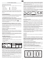 3
3
-
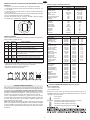 4
4
-
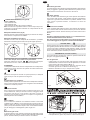 5
5
-
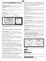 6
6
-
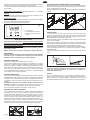 7
7
-
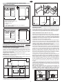 8
8
-
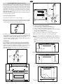 9
9
-
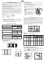 10
10
-
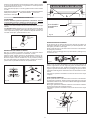 11
11
-
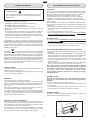 12
12
-
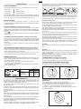 13
13
-
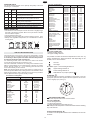 14
14
-
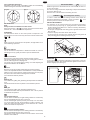 15
15
-
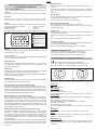 16
16
-
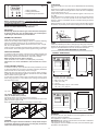 17
17
-
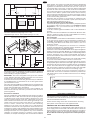 18
18
-
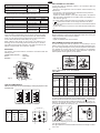 19
19
-
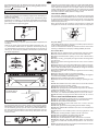 20
20
-
 21
21
-
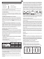 22
22
-
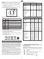 23
23
-
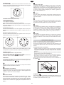 24
24
-
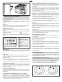 25
25
-
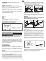 26
26
-
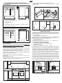 27
27
-
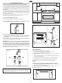 28
28
-
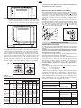 29
29
-
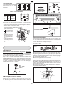 30
30
-
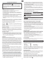 31
31
-
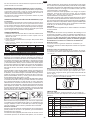 32
32
-
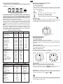 33
33
-
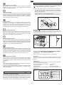 34
34
-
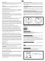 35
35
-
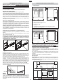 36
36
-
 37
37
-
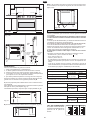 38
38
-
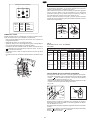 39
39
-
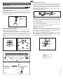 40
40


Brandt DCM390XE1 Manuale del proprietario
- Categoria
- Piani cottura
- Tipo
- Manuale del proprietario
in altre lingue
- English: Brandt DCM390XE1 Owner's manual
- français: Brandt DCM390XE1 Le manuel du propriétaire
- español: Brandt DCM390XE1 El manual del propietario
Altri documenti
-
Hoover HPD90 Manuale utente
-
-
Zoppas PXX900AMS Manuale utente
-
-
Zerowatt-Hoover CFHGR266AMXS Manuale utente
-
Glem GE960CMBK Manuale del proprietario
-
-
Candy CF CC 95 JC Manuale utente
-
-