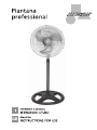
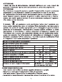
Johnson PIANTANA PROFESSIONAL Manuale utente
- Tipo
- Manuale utente


74,75
54,48
1,59
0,00
64,96
3,53
15,96

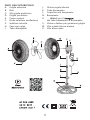
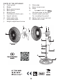
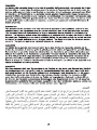
PARTI DELLʼAPPARECCHIO
A. Griglia anteriore
B. Pale
C. Viti griglia posteriore
D. Griglia posteriore
E. Corpo motore
F. Perno selettore oscillazione
G. Selettore velocità
H. Cavo con spina
I. Tubo allungabile
J. Ghiera regola altezza
K. Tubo basamento
L. Copertura viti basamento
N. Basamento
O. Viti e dadi per il
del tubo basamento al basamento
V. Vitina e dadino per giunzione griglie
W. Vite e dado blocca motore
X. Vite blocca pale


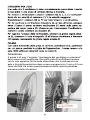
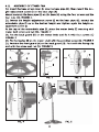
il punto 4 di pag. 7 sezione “montaggio del ventilatore a piantana”
deve essere così modificato: fissare le pale (B) sull’albero motore
con la vite apposita (X) facendo attenzione che la distanza tra la
pala e la griglia posteriore deve essere compresa tra 5 mm e 10 mm
come da foto. Un errato posizionamento della ventola potrebbe
provocare delle vibrazioni.
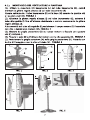
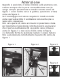
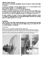
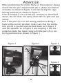
Attenzione

Attenzione
Quando si posiziona il corpo motore sulla piantana con-
trollare sempre che la parte contraddistinta con (A)
venga sempre posizionata in modo corretto come da
figura 1 e non rivolta verso la gabbia, (posizione errata)
come da figura 2.
Se il montaggio non viene eseguito in modo corretto
come sopra descritto il ventilatore non oscilla (da sx
verso dx e viceversa).
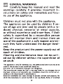
N.B. se la parte (A) viene a trovarsi in posizione errata
per riportarla in posizione corretta occorre assicurarsi
che il perno oscillazione (B) sia spinto verso il basso
come in figura 3 e non verso l’alto come in figura
4 e tenendo fermo la piantana ruotare il corpo motore
fino a posizionare correttamente la parte (A) come da
figura 1
figura 1 figura 2
figura 4
figura 3
A
A
A
A
B
B
NO
NO


74,75
54,48
1,59
0,00
64,96
3,53
15,96

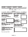
PARTS OF THE APPLIANCE
A. Front guard
B. Blades
C. Back guard screws
D. Back guard
E. Motor body
F. Oscillation selector pin
G. Speed selector
H. Cable with plug
I. Extendable pipe
J. Height-adjustment screw
K. Base pipe
L. Base screw cover
N. Base
O. Screws and nuts for
the base pipe to the base
V. Small screws and nuts
for coupling the guard
W. Motor lock screw and nut
X. Blade lock screw


point 4 on p. 15 section "mounting the floor fan"
it must be modified as follows: fix the blades (B) on the motor shaft
with the appropriate screw (X) making sure that the distance between
the blade and rear grill must be between 5 mm and 10 mm as in the
photo. Incorrect positioning of the fan could cause vibrations.
Attention

Attention
When positioning the motor body on the pedestal, always
check that the part marked with (A) is always positioned
correctly as shown in figure 1 and not facing the cage,
(wrong position) as shown in figure 2.
If the assembly is not carried out correctly as described
above, the fan does not swing (from left to right and vice
versa).
N.B. if the part (A) is in the wrong position to bring it
back to the correct position, make sure that the oscilla-
tion pin (B) is pushed and pushed down as in figure 3
and not upwards as in figure 4 and keeping it still the
pedestal rotate the motor body until the part (A) is cor-
rectly positioned as shown in figure 1
figura 1 figura 2
figura 4
figura 3
A
A
A
A
B
B
NO
NO


-
 1
1
-
 2
2
-
 3
3
-
 4
4
-
 5
5
-
 6
6
-
 7
7
-
 8
8
-
 9
9
-
 10
10
-
 11
11
-
 12
12
-
 13
13
-
 14
14
-
 15
15
-
 16
16
-
 17
17
-
 18
18
-
 19
19
-
 20
20


