RKC INSTRUMENT SRZ Communication Instruction Manual
- Tipo
- Communication Instruction Manual

Communication Extension
Module
Z
-
CO
M
Host Communication
Instruction Manual
Module Type Controller SRZ
IMS01T23-E4
RKC INSTRUMENT INC.
®

All Rights Reserved, Copyright 2008, RKC INSTRUMENT INC.
Modbus is a registered trademark of Schneider Electric.
The name of each programmable controller (PLC) means the products of each manufacturer.
Company names and product names used in this manual are the trademarks or registered trademarks of
the respective companies.

IMS01T23-E4
i-1
Thank you for purchasing this RKC product. In order to achieve maximum performance and ensure proper
operation of the instrument, carefully read all the instructions in this manual. Please place the manual in a
convenient location for easy reference.
SYMBOLS
: This mark indicates that all precautions should be taken for safe usage.
: This mark indicates important information on installation, handling and operating
procedures.
: This mark indicates supplemental information on installation, handling and
operating procedures.
: This mark indicates where additional information may be located.
To prevent injury to persons, damage to the instrument and the equipment, a
suitable external protection device shall be required.
All wiring must be completed before power is turned on to prevent electric
shock, fire or damage to the instrument and the equipment.
This instrument must be used in accordance with the specifications to prevent
fire or damage to the instrument and the equipment.
This instrument is not intended for use in locations subject to flammable or
explosive gases.
Do not touch high-voltage connections such as power supply terminals, etc. to
avoid electric shock.
RKC is not responsible if this instrument is repaired, modified or disassembled
by other than factory-approved personnel. Malfunction may occur and
warranty is void under these conditions.
: This mark indicates precautions that must be taken if there is danger of electric
shock, fire, etc., which could result in loss of life or injury.
: This mark indicates that if these precautions and operating procedures are not taken,
damage to the instrument may result.
WARNING
!
CAUTION
WARNING
!

IMS01T23-E4
i-2
This product is intended for use with industrial machines, test and measuring equipment.
(It is not designed for use with medical equipment and nuclear energy plant.)
This is a Class A instrument. In a domestic environment, this instrument may cause radio
interference, in which case the user may be required to take additional measures.
This instrument is protected from electric shock by reinforced insulation. Provide reinforced
insulation between the wire for the input signal and the wires for instrument power supply,
source of power and loads.
Be sure to provide an appropriate surge control circuit respectively for the following:
- If input/output or signal lines within the building are longer than 30 meters.
- If input/output or signal lines leave the building, regardless the length.
This instrument is designed for installation in an enclosed instrumentation panel. All
high-voltage connections such as power supply terminals must be enclosed in the
instrumentation panel to avoid electric shock to operating personnel.
All precautions described in this manual should be taken to avoid damage to the instrument or
equipment.
If the equipment is used in a manner not specified by the manufacturer, the protection
provided by the equipment may be impaired.
All wiring must be in accordance with local codes and regulations.
All wiring must be completed before power is turned on to prevent electric shock, instrument
failure, or incorrect action. The power must be turned off before repairing work for input break
and output failure including replacement of sensor, contactor or SSR, and all wiring must be
completed before power is turned on again.
To prevent instrument damage as a result of failure, protect the power line and the
input/output lines from high currents with a suitable overcurrent protection device with
adequate breaking capacity such as a fuse, circuit breaker, etc.
A malfunction in this product may occasionally make control operations impossible or prevent
alarm outputs, resulting in a possible hazard. Take appropriate measures in the end use to
prevent hazards in the event of malfunction.
Prevent metal fragments or lead wire scraps from falling inside instrument case to avoid
electric shock, fire or malfunction.
Tighten each terminal screw to the specified torque found in the manual to avoid electric shock,
fire or malfunction.
For proper operation of this instrument, provide adequate ventilation for heat dissipation.
Do not connect wires to unused terminals as this will interfere with proper operation of the
instrument.
Turn off the power supply before cleaning the instrument.
Do not use a volatile solvent such as paint thinner to clean the instrument. Deformation or
discoloration may occur. Use a soft, dry cloth to remove stains from the instrument.
To avoid damage to the instrument display, do not rub with an abrasive material or push the
front panel with a hard object.
Do not connect modular connectors to telephone line.
NOTICE
This manual assumes that the reader has a fundamental knowledge of the principles of electricity,
process control, computer technology and communications.
The figures, diagrams and numeric values used in this manual are only for explanation purpose.
RKC is not responsible for any damage or injury that is caused as a result of using this instrument,
instrument failure or indirect damage.
RKC is not responsible for any damage and/or injury resulting from the use of instruments made by
imitating this instrument.
Periodic maintenance is required for safe and proper operation of this instrument. Some components
have a limited service life, or characteristics that change over time.
Every effort has been made to ensure accuracy of all information contained herein. RKC makes no
warranty, expressed or implied, with respect to the accuracy of the information. The information in this
manual is subject to change without prior notice.
No portion of this document may be reprinted, modified, copied, transmitted, digitized, stored,
processed or retrieved through any mechanical, electronic, optical or other means without prior written
approval from RKC.
CAUTION

IMS01T23-E4 i-3
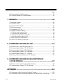
CONTENTS
Page
1. OUTLINE .............................................................................. 1
2. COMMUNICATION SPECIFICATION .................................. 2
3. WIRING ................................................................................. 4
3.1 When Connected with RS-422A ...................................................................... 5
When the interface of host computer is RS-232C ........................................................... 6
When the interface of host computer is RS-422A............................................................ 7
When the host computer has a USB connector .............................................................. 8
3.2 When Connected with RS-485 ........................................................................ 9
When the interface of host computer is RS-232C ......................................................... 10
When the interface of host computer is RS-485 ............................................................ 11
When the host computer has a USB connector ............................................................ 12
3.3 Multiple SRZ Unit Connections ...................................................................... 13
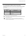
3.4 Termination Resistor of Z-COM Module ........................................................ 14
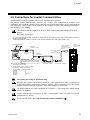
3.5 Connections for Loader Communication ....................................................... 15
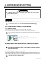
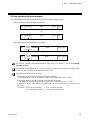
4. COMMUNICATION SETTING ............................................ 16
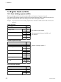
4.1 Communication Setting of Z-COM Module .................................................... 16
4.1.1 Address setting ........................................................................................................ 16
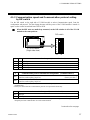
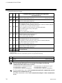
4.1.2 Communication speed and Communication protocol setting by DIP switch ............. 17
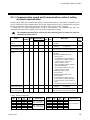
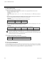
4.1.3 Communication speed and Communication protocol setting via Host communication .. 19
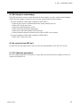
4.1.4 Communication setting for Loader communication .................................................. 21
4.2 Communication Setting of the Function Modules .......................................... 22
4.2.1 Address setting of the function modules .................................................................. 22
4.2.2 Channel of the SRZ unit ........................................................................................... 23
5. COMMUNICATION REQUIREMENTS ............................... 24
6. RKC COMMUNICATION .................................................... 26
6.1 Polling ............................................................................................................ 26
6.1.1 Polling procedures ................................................................................................... 27
6.1.2 Polling procedure example (when the host computer sends data) ............................... 31
6.2 Selecting ........................................................................................................ 32
6.2.1 Selecting procedures ............................................................................................... 32
6.2.2 Selecting procedure example (when the host computer sends data) ........................... 36

IMS01T23-E4
i-4
Page
6.3 Communication Data Structure ...................................................................... 37
6.4 Channel Number of Communication .............................................................. 39
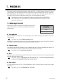
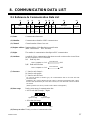
7. MODBUS............................................................................. 42
7.1 Message Format ............................................................................................ 42
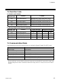
7.2 Function Code ............................................................................................... 43
7.3 Communication Mode .................................................................................... 43
7.4 Slave Responses ........................................................................................... 44
7.5 Calculating CRC-16 ....................................................................................... 45
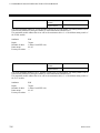
7.6 Register Read and Write ............................................................................... 48
7.6.1 Read holding registers [03H] .................................................................................... 48
7.6.2 Preset single register [06H] ...................................................................................... 49
7.6.3 Diagnostics (Loopback test) [08H] ........................................................................... 50
7.6.4 Preset multiple registers [10H] ................................................................................. 51
7.7 Data Processing Precautions ........................................................................ 52
7.8 How to Use Memory Area Data ..................................................................... 53
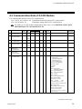
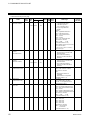
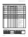
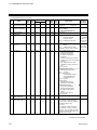
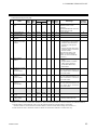
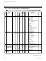
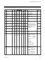
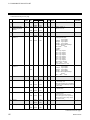
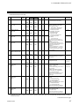
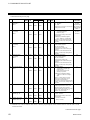
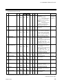
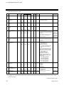
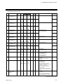
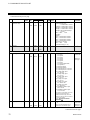
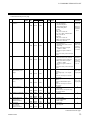
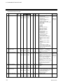
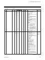
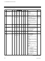
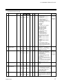
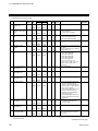
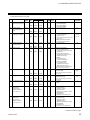
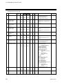
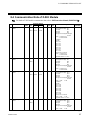
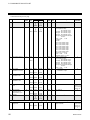
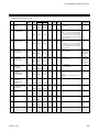
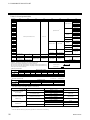
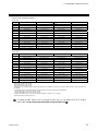
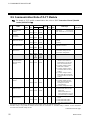
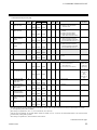
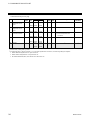
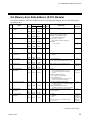
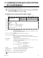
8. COMMUNICATION DATA LIST ......................................... 57
8.1 Reference to Communication Data List ......................................................... 57
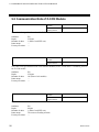
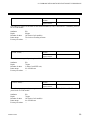
8.2 Communication Data of Z-COM Module ........................................................ 59
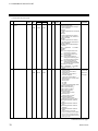
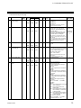
8.3 Communication Data of Z-TIO Module .......................................................... 64
8.4 Communication Data of Z-DIO Module .......................................................... 87
8.5 Communication Data of Z-CT Module ........................................................... 92
8.6 Memory Area Data Address (Z-TIO Module) ................................................. 95
9. COMMUNICATION DATA DESCRIPTION OF
Z-COM MODULE ............................................................... 97
9.1 Reference to Communication Data Contents ................................................ 97
9.2 Communication Data of Z-COM Module ........................................................ 98
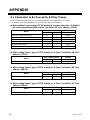
APPENDIX ............................................................................ 118
A.1 Parameters to Be Unused by Setting Change............................................. 118
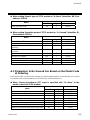
A.2 Parameters to Be Unused Are Based on the Model Code at Ordering ......... 119

IMS01T23-E4 1
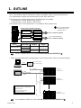
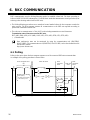
1. OUTLINE
The Z-COM module interfaces with the host computer via Modbus or RKC communication protocols.
The communication interface used for both protocols is RS-422A and RS-485.
The following two communication systems of Z-COM module are available.
Communication 1 (COM. PORT1, COM. PORT2)
Communication 2 (COM. PORT3, COM.PORT4)
Both communication 1 and communication 2 are available as Host communication.
Z-COM module internal block diagram
COM
Communication 1
COM. PORT1
Communication 2
Host communication
COM. PORT2
COM. PORT3
COM. PORT4
There is isolation between
“Communication 1” and
“Communication 2.”
PLC communication or
Host communication
COM. PORT
Usage 1 Usage 2
Communication 1
COM. PORT1
Host
communication
Host
communication
COM. PORT2
Communication 2
COM. PORT3
PLC
communication
Host
communication
COM. PORT4
For PLC communication, refer to Z-COM Instruction Manual (IMS01T22-E).
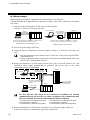
Usage example (When both communication 1 and communication 2 are Host communication.)
Host computer
RS-232C
Host communication
(RKC communication)
RS-232C/
RS-422A
converter
RS-422A
Up to 16 SRZ units can be multi-drop connected
to one host computer (or operation panel)
communication port.
Number of temperature control:
1024 channels maximum
RS-422A
Host communication
(Modbus)
Operation panel
SRZ unit 1
(Unit address 0)
SRZ unit 2
(Unit address 1)
SRZ unit 16
(Unit address 15 [F])
For configuration of SRZ unit, refer to Z-COM Instruction Manual (IMS01T22-E).

2 IMS01T23-E4
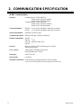
2. COMMUNICATION SPECIFICATION
RKC communication
Interface: Communication 1 (COM. PORT1/2):
Based on EIA, RS-422A standard
Based on EIA, RS-485 standard
Communication 2 (COM. PORT3/4):
Based on EIA, RS-422A standard
Based on EIA, RS-485 standard
Connection method: RS-422A 4-wire system, half-duplex multi-drop connection
RS-485 2-wire system, half-duplex multi-drop connection
Synchronous method: Start/Stop synchronous type
Communication speed: 4800 bps, 9600 bps, 19200 bps, 38400 bps
Data bit configuration: Start bit: 1
Data bit: 7 or 8
Parity bit: Without, Odd or Even
Stop bit: 1
Protocol: Based on ANSI X3.28-1976 subcategories 2.5 and B1
Polling/Selecting type
Error control: Vertical parity (with parity bit selected)
Horizontal parity (BCC check)
Data types: ASCII 7-bit code
Interval time: 0 to 250 ms
Maximum connections: 16 SRZ units per communication port of host computer
(Up to one Z-COM module can be connected to one SRZ unit)

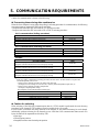
2. COMMUNICATION SPECIFICATION
IMS01T23-E4
3
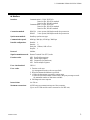
Modbus
Interface: Communication 1 (COM. PORT1/2):
Based on EIA, RS-422A standard
Based on EIA, RS-485 standard
Communication 2 (COM. PORT3/4):
Based on EIA, RS-422A standard
Based on EIA, RS-485 standard
Connection method: RS-422A 4-wire system, half-duplex multi-drop connection
RS-485 2-wire system, half-duplex multi-drop connection
Synchronous method: Start/Stop synchronous type
Communication speed: 4800 bps, 9600 bps, 19200 bps, 38400 bps
Data bit configuration: Start bit: 1
Data bit: 8
Parity bit: Without, Odd or Even
Stop bit: 1
Protocol: Modbus
Signal transmission mode: Remote Terminal Unit (RTU) mode
Function codes: 03H Read holding registers
06H Preset single register
08H Diagnostics (loopback test)
10H Preset multiple registers
Error check method: CRC-16
Error codes: 1: Function code error
(An unsupported function code was specified)
2: When the mismatched address is specified.
3: When the data written exceeds the setting range.
When the specified number of data items in the query message exceeds
the maximum number of data items available
4: Self-diagnostic error response
Interval time: 0 to 250 ms
Maximum connections: 16 SRZ units per communication port of host computer
(Up to one Z-COM module can be connected to one SRZ unit)

4 IMS01T23-E4
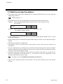
3. WIRING
To avoid noise induction, keep communication signal wire away from instrument power line,
load lines and power lines of other electric equipment.
Connect connectors correctly in the right position. If it is forcibly pushed in with pins in the
wrong positions, the pins may be bent resulting in instrument failure.
When connecting or disconnecting the connectors, do not force it too far to right and left or
up and down, but move it on the straight. Otherwise, the connector pins may be bent,
causing instrument failure.
When disconnecting a connector, hold it by the connector itself. Disconnecting connectors
by yanking on their cables can cause breakdowns.
To prevent malfunction, never touch the contact section of a connector with bare hands or
with hands soiled with oil or the like.
To prevent malfunction, connect cable connectors securely, then firmly tighten the
connector fastening screws.
To prevent damage to cables, do not bend cables over with excessive force.
If the instrument is easily affected by noise, use the ferrite core in the both ends of the
communication cable (nearest the connector).
To prevent electric shock or instrument failure, turn off the power before
connecting or disconnecting the instrument and peripheral equipment.
WARNING
!
CAUTION

3. WIRING
IMS01T23-E4 5
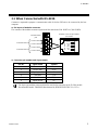
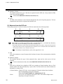
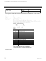
3.1 When Connected with RS-422A
Customer is requested to prepare a communication cable fit for the SRZ unit to be connected by the host
computer.
Pin layout of modular connector
The contents of the modular connector signal are all the same from COM. PORT1 to COM. PORT4.
COM. PORT1
Communication 2
Communication 1
COM. PORT2
COM. PORT3
COM. PORT4
COM
Modular connector pin number
(RS-422A)
1 R (A)
2 R (B)
3 SG
4 T (B)
5 T (A)
6 SG
Communication
port
Connector pin number and signal details
Pin No. Signal name Symbol
1
Receive data R (A)
2
Receive data R (B)
3
Signal ground SG
4
Send data T (B)
5
Send data T (A)
6
Signal ground SG
The 6-pin type modular connector should be used for the connection to the Z-COM module.
Recommended model: TM4P-66P (Manufactured by HIROSE ELECTRIC CO., LTD.)

3. WIRING
IMS01T23-E4
6
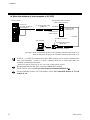
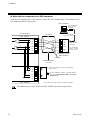
When the interface of host computer is RS-232C
COM
Communication cable
(W-BF-02)
Connect to the communication connector
Host computer
RS-232C
Connect to the
COM. PORT1
RS-422A
Connect to the
COM. PORT2
RS-232C/RS-422A converter
COM-A (RKC product)
Connect to
the COM. PORT1 or
COM. PORT3
Z-COM module
Cable type: W-BF-02-3000 (RKC product, Sold separately) [Standard cable length: 3 m]
W-BF-28-3000 (RKC product, Sold separately) [Standard cable length: 3 m]
Communication cable
(W-BF-28)
D-SUB 9P connector
W-BF-02 * or W-BF-28 communication cable (RKC product) can be used as communication
cable (sold separately). If noise is a factor, customer should use a twisted pair cable (not
included) or something to that effect.
* Shield of the cable are connected to SG (No. 6 pin) of the Z-COM modular connector.
Recommended RS-232C/RS-422A converter: COM-A (RKC product)
For the COM-A, refer to COM-A/COM-B Instruction Manual (IMSRM33-E).
For the termination resistor of Z-COM module, refer to 3.4 Termination Resistor of Z-COM
Module (P. 14).

3. WIRING
IMS01T23-E4
7
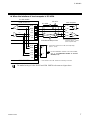
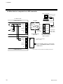
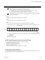
When the interface of host computer is RS-422A
Shielded twisted pair wire
Pair wire
Host computer
T (A)
T (B)
SG
R (A)
R (B)
RS-422A
1
2
3
4
5
6
R1
R1
R1: Termination Resistor
(Example: 120 1/2 W)
(Host computer side)
* COM. PORT1 and COM. PORT2 are internally connected.
R2: Termination resistor for Z-COM (Sold separately)
[120 1/2 W]
1
R (A)
R (B)
SG
T (B)
T (A)
SG
COM. PORT1 *
2
3
4
5
6
R (A)
R (B)
SG
T (B)
T (A)
SG
COM. PORT2 *
R2
R2
Z-COM module
()
()
()
()
()
()
()
()
For the termination resistor of Z-COM module,
refer to 3.4 Termination Resistor of Z-COM
Module (P. 14).
The method wiring of COM. PORT3 and COM. PORT4 is the same as a figure above.

3. WIRING
IMS01T23-E4
8
When the host computer has a USB connector
When the host computer has a USB connector, connect the USB communication converter between the
host computer and the Z-COM module.
Host computer
USB communication
converter COM-K
(RKC product)
Connected to USB
port of personal
computer
USB cable
(COM-K accessory)
Connected to
USB connector
of COM-K
The termination
resistor is built
into the COM-K.
RS-422A
SG
2
4
3
5
T (A)
T (B)
Shielded twisted
pair wire
1
R (A)
R (B)
SG
T (B)
T (A)
SG
COM. PORT1 *
2
3
4
5
6
R (A)
R (B)
SG
T (B)
T (A)
SG
COM. PORT2 *
R2
R2
Z-COM module
R2: Termination resistor for Z-COM (Sold separately)
[120 1/2 W]
R (A)
R (B)
Pair wire
* COM. PORT1 and COM. PORT2 are internally connected.
1
2
3
4
5
6
1
()
(
)
(
)
(
)
For the termination resistor of Z-COM module,
refer to 3.4 Termination Resistor of Z-COM
Module (P. 14).
The method wiring of COM. PORT3 and COM. PORT4 is the same as a figure above.

3. WIRING
IMS01T23-E4
9
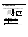
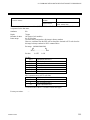
3.2 When Connected with RS-485
Customer is requested to prepare a communication cable fit for the SRZ unit to be connected by the host
computer.
Pin layout of modular connector
The contents of the modular connector signal are all the same from COM. PORT1 to COM. PORT4.
Communication
port
COM. PORT1
Communication 2
Communication 1
COM. PORT2
COM. PORT3
COM. PORT4
COM
Modular connector pin number
(RS-485)
1
T/R (A)
2
T/R (B)
3
SG
4
Unused
5
Unused
6
SG
Connector pin number and signal details
Pin No. Signal name Symbol
1
Send/Receive data T/R (A)
2
Send/Receive data T/R (B)
3
Signal ground SG
4
Unused
5
Unused
6
Signal ground SG
The 6-pin type modular connector should be used for the connection to the Z-COM module.
Recommended model: TM4P-66P (Manufactured by HIROSE ELECTRIC CO., LTD.)

3. WIRING
IMS01T23-E4
10
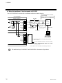
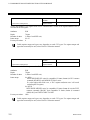
When the interface of host computer is RS-232C
Use a RS-232C/RS-485 converter with an automatic send/receive transfer function.
Host computer
SG
T/R (A)
T/R (B)
RS-232C/RS-485 converter
Rcommended:
CD485, CD485/V manufactured
by Data Link, Inc. or equivalent.
RS-232C
Pair wire
RS-485
Shielded twisted
pair wire
R1
R1: Termination resistor
Example:
120
1/2 W
Converter side
COM. PORT1 *
1
2
3
4
5
6
T/R (A)
T/R (B)
SG
Unused
Unused
SG
Z-COM module
1
2
3
4
5
6
T/R (A)
T/R (B)
SG
Unused
Unused
SG
COM. PORT2 *
R2
R2: Termination resistor for Z-COM (Sold separately)
[120
1/2 W]
* COM. PORT1 and COM. PORT2 are internally connected.
()
()
For the termination resistor of Z-COM module,
refer to
3.4 Termination Resistor of Z-COM
Module (P. 14)
.
The method wiring of COM.PORT3 and COM.PORT4 is the same as a figure above.

3. WIRING
IMS01T23-E4
11
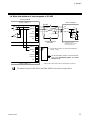
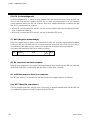
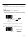
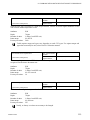
When the interface of host computer is RS-485
Shielded twisted
pair wire
Pair wire
RS-485
R1
Host computer
SG
T/R (B)
T/R (A)
R1: Termination resistor
(Example: 120
1/2 W)
(Host computer side)
COM. PORT1 *
1
2
3
4
5
6
T/R (A)
T/R (B)
SG
Unused
Unused
SG
Z-COM module
1
2
3
4
5
6
T/R (A)
T/R (B)
SG
Unused
Unused
SG
COM. PORT2 *
R2
R2: Termination resistor for Z-COM (Sold separately)
[120
1/2 W]
* COM. PORT1 and COM. PORT2 are internally connected.
()
()
()
()
For the termination resistor of Z-COM module,
refer to
3.4 Termination Resistor of Z-COM
Module (P. 14)
.
The method wiring of COM. PORT3 and COM. PORT4 is the same as a figure above.

3. WIRING
IMS01T23-E4
12
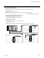
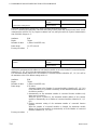
When the host computer has a USB connector
Host computer
USB communication
converter COM-K
(RKC product)
Connected to USB
port of a personal
computer
USB cable
(COM-K accessory)
Connected to
USB connector
of COM-K
The termination
resistor is built
into the COM-K.
RS-485
1
SG
2
4
3
5
T/R (A)
T/R (B)
Unused
Shielded twisted
pair wire
Pair wire
COM. PORT1 *
1
2
3
4
5
6
T/R (A)
T/R (B)
SG
Unused
Unused
SG
Z-COM module
1
2
3
4
5
6
T/R (A)
T/R (B)
SG
Unused
Unused
SG
COM. PORT2 *
R2
R2: Z-COM (Sold separately)
[120
1/2 W]
* COM. PORT1 and COM. PORT2 are internally connected.
()
()
For the termination resistor of Z-COM module,
refer to
3.4 Termination Resistor of Z-COM
Module (P. 14).

3. WIRING
IMS01T23-E4
13
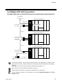
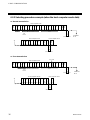
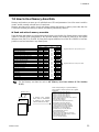
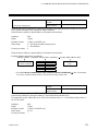
3.3 Multiple SRZ Unit Connections
[Example: When two or more SRZ units are connected to the communication 1]
Connect to the
COM. PORT2
SRZ unit 1 (Unit address 0)
SRZ unit 2 (Unit address 1)
SRZ unit 3 (Unit address 2)
Connect to the
COM. PORT1
Connect to the
COM. PORT2
Communication 1
If communication errors occur frequently,
connect termination resistor to the Z-COM
module.
Connect to the COM. PORT2
Host computer
or
Operation panel
Connect to the
COM. PORT1
Connect to the
COM. PORT1
W-BF-02
W-BF-02
For RS-422A interface, order W-BF-02 connection cable (sold separately) to connect the SRZ
unit. If noise is a factor, customer should use a twisted pair cable (not included) or something to
that effect.
Cable type: W-BF-02-3000 (Sold separately) [Standard cable length: 3 m]
COM. PORT1 and COM. PORT2 are internally connected.
This description also applies even when the communication 2 is connected.
For the termination resistor of Z-COM module, refer to
3.4 Termination Resistor of Z-COM
Module (P. 14).

3. WIRING
IMS01T23-E4
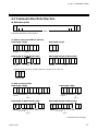
14
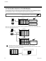
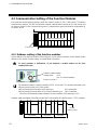
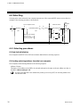
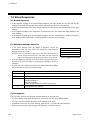
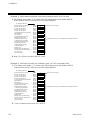
3.4 Termination Resistor of Z-COM Module
If communication errors occur frequently due to the operation environment or the communication distance,
connect termination resistors to the Z-COM module and the other party unit. For the termination resistor of
the Z-COM module, connect a Z-COM termination resistor connector (sold separately).
Termination resistor for Z-COM (Sold separately): W-BW-01 (for RS-485) [120 1/2 W]
W-BW-02 (for RS-422A) [120
1/2 W]
For the termination resistor of the other party unit, refer to the other party unit Instruction Manual.
Host computer
Operation panel
SRZ unit 1
(Unit address 0)
When the COM. PORT1 is used:
Insert the termination resistor to
COM. PORT2.
When the COM. PORT3 is used:
Insert the termination resistor to
COM. PORT4.
When two or more SRZ units are connected, connect a termination resistor to the Z-COM module at the
farthest end of the communication line.
Host computer
Operation panel
SRZ unit 1
(Unit address 0)
SRZ unit 16
(Unit address F)
Connect a termination
resistor to the Z-COM
module at the farthest
end of the communication
line.
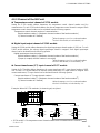
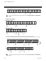
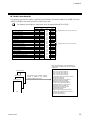
Termination resistor of the function modules (Z-TIO, Z-DIO and Z-CT modules):
When using a Z-COM module joined together with function modules, there is no need to connect
a termination resistor to the function modules.
SRZ unit
12
345
Not necessary
Function modules
There is no need to connect a termination
resistor to the base of the function module.
La pagina si sta caricando...
La pagina si sta caricando...
La pagina si sta caricando...
La pagina si sta caricando...
La pagina si sta caricando...
La pagina si sta caricando...
La pagina si sta caricando...
La pagina si sta caricando...
La pagina si sta caricando...
La pagina si sta caricando...
La pagina si sta caricando...
La pagina si sta caricando...
La pagina si sta caricando...
La pagina si sta caricando...
La pagina si sta caricando...
La pagina si sta caricando...
La pagina si sta caricando...
La pagina si sta caricando...
La pagina si sta caricando...
La pagina si sta caricando...
La pagina si sta caricando...
La pagina si sta caricando...
La pagina si sta caricando...
La pagina si sta caricando...
La pagina si sta caricando...
La pagina si sta caricando...
La pagina si sta caricando...
La pagina si sta caricando...
La pagina si sta caricando...
La pagina si sta caricando...
La pagina si sta caricando...
La pagina si sta caricando...
La pagina si sta caricando...
La pagina si sta caricando...
La pagina si sta caricando...
La pagina si sta caricando...
La pagina si sta caricando...
La pagina si sta caricando...
La pagina si sta caricando...
La pagina si sta caricando...
La pagina si sta caricando...
La pagina si sta caricando...
La pagina si sta caricando...
La pagina si sta caricando...
La pagina si sta caricando...
La pagina si sta caricando...
La pagina si sta caricando...
La pagina si sta caricando...
La pagina si sta caricando...
La pagina si sta caricando...
La pagina si sta caricando...
La pagina si sta caricando...
La pagina si sta caricando...
La pagina si sta caricando...
La pagina si sta caricando...
La pagina si sta caricando...
La pagina si sta caricando...
La pagina si sta caricando...
La pagina si sta caricando...
La pagina si sta caricando...
La pagina si sta caricando...
La pagina si sta caricando...
La pagina si sta caricando...
La pagina si sta caricando...
La pagina si sta caricando...
La pagina si sta caricando...
La pagina si sta caricando...
La pagina si sta caricando...
La pagina si sta caricando...
La pagina si sta caricando...
La pagina si sta caricando...
La pagina si sta caricando...
La pagina si sta caricando...
La pagina si sta caricando...
La pagina si sta caricando...
La pagina si sta caricando...
La pagina si sta caricando...
La pagina si sta caricando...
La pagina si sta caricando...
La pagina si sta caricando...
La pagina si sta caricando...
La pagina si sta caricando...
La pagina si sta caricando...
La pagina si sta caricando...
La pagina si sta caricando...
La pagina si sta caricando...
La pagina si sta caricando...
La pagina si sta caricando...
La pagina si sta caricando...
La pagina si sta caricando...
La pagina si sta caricando...
La pagina si sta caricando...
La pagina si sta caricando...
La pagina si sta caricando...
La pagina si sta caricando...
La pagina si sta caricando...
La pagina si sta caricando...
La pagina si sta caricando...
La pagina si sta caricando...
La pagina si sta caricando...
La pagina si sta caricando...
La pagina si sta caricando...
La pagina si sta caricando...
La pagina si sta caricando...
La pagina si sta caricando...
La pagina si sta caricando...
La pagina si sta caricando...
La pagina si sta caricando...
-
 1
1
-
 2
2
-
 3
3
-
 4
4
-
 5
5
-
 6
6
-
 7
7
-
 8
8
-
 9
9
-
 10
10
-
 11
11
-
 12
12
-
 13
13
-
 14
14
-
 15
15
-
 16
16
-
 17
17
-
 18
18
-
 19
19
-
 20
20
-
 21
21
-
 22
22
-
 23
23
-
 24
24
-
 25
25
-
 26
26
-
 27
27
-
 28
28
-
 29
29
-
 30
30
-
 31
31
-
 32
32
-
 33
33
-
 34
34
-
 35
35
-
 36
36
-
 37
37
-
 38
38
-
 39
39
-
 40
40
-
 41
41
-
 42
42
-
 43
43
-
 44
44
-
 45
45
-
 46
46
-
 47
47
-
 48
48
-
 49
49
-
 50
50
-
 51
51
-
 52
52
-
 53
53
-
 54
54
-
 55
55
-
 56
56
-
 57
57
-
 58
58
-
 59
59
-
 60
60
-
 61
61
-
 62
62
-
 63
63
-
 64
64
-
 65
65
-
 66
66
-
 67
67
-
 68
68
-
 69
69
-
 70
70
-
 71
71
-
 72
72
-
 73
73
-
 74
74
-
 75
75
-
 76
76
-
 77
77
-
 78
78
-
 79
79
-
 80
80
-
 81
81
-
 82
82
-
 83
83
-
 84
84
-
 85
85
-
 86
86
-
 87
87
-
 88
88
-
 89
89
-
 90
90
-
 91
91
-
 92
92
-
 93
93
-
 94
94
-
 95
95
-
 96
96
-
 97
97
-
 98
98
-
 99
99
-
 100
100
-
 101
101
-
 102
102
-
 103
103
-
 104
104
-
 105
105
-
 106
106
-
 107
107
-
 108
108
-
 109
109
-
 110
110
-
 111
111
-
 112
112
-
 113
113
-
 114
114
-
 115
115
-
 116
116
-
 117
117
-
 118
118
-
 119
119
-
 120
120
-
 121
121
-
 122
122
-
 123
123
-
 124
124
-
 125
125
-
 126
126
-
 127
127
-
 128
128


RKC INSTRUMENT SRZ Communication Instruction Manual
- Tipo
- Communication Instruction Manual
in altre lingue
- English: RKC INSTRUMENT SRZ
Documenti correlati
-
RKC INSTRUMENT COM-MY Communication Data List
-
-
-
-
-
-
-
-
-