
Bedienungsanleitung
Operation Manual
Innovation,
die bewegt!
Licht-Sperrsignal
Hohe/niedere Bauart
Colour light stop signal
High/low type
H0: 4017, 4018
TT: 4917
N: 4417, 4418
Z: 4818
1. Wichtige Hinweise / Important information ..................................................... 2
2. Einleitung / Introduction .................................................................................. 2
3. Signaltechnik / Signal technology ................................................................... 3
4. Einbau / Mounting ........................................................................................... 3
5. Anschluss / Connection .................................................................................. 3
6. Technische Daten / Technical data ................................................................. 4

2
DE EN
1. Wichtige Hinweise
Bitte lesen Sie vor der ersten Anwendung des Produktes
bzw. dessen Einbau diese Bedienungsanleitung aufmerksam
durch. Bewahren Sie diese auf, sie ist Teil des Produktes.
1.1 Sicherheitshinweise
Vorsicht:
Verletzungsgefahr!
Aufgrund der detaillierten Abbildung des Originals bzw.
der vorgesehenen Verwendung kann das Produkt Spit-
zen, Kanten und abbruchgefährdete Teile aufweisen. Für
die Montage sind Werkzeuge nötig.
Stromschlaggefahr!
Die Anschlussdrähte niemals in eine Steckdose einfüh-
ren! Verwendetes Versorgungsgerät (Transformator,
Netzteil) regelmäßig auf Schäden überprüfen. Bei Schä-
den am Versorgungsgerät dieses keinesfalls benutzen!
Alle Anschluss- und Montagearbeiten nur bei abgeschal
-
teter Betriebsspannung durchführen!
Ausschließlich nach VDE/EN gefertigte Modellbahn-
transformatoren verwenden!
Stromquellen unbedingt so absichern, dass es bei ei-
nem Kurzschluss nicht zum Kabelbrand kommen kann.
1.2 Das Produkt richtig verwenden
Dieses Produkt ist bestimmt:
- Zum Einbau in Modelleisenbahnanlagen und Dioramen.
- Zum Anschluss an einen Modellbahntransformator
(z. B. Art. 5200) bzw. an eine Modellbahnsteuerung mit
zugelassener Betriebsspannung.
- Zum Betrieb in trockenen Räumen.
Jeder darüber hinausgehende Gebrauch gilt als nicht be-
stimmungsgemäß. Für daraus resultierende Schäden haf-
tet der Hersteller nicht.
1.3 Packungsinhalt überprüfen
Kontrollieren Sie den Lieferumfang auf Vollständigkeit:
- Licht-Sperrsignal mit Steckfuß, 2 Widerständen und Di-
ode
- Haltering
- Etikett mit selbstklebenden Bezeichnungsschildern
- Anleitung
2. Einleitung
Sperrsignale gehören der Kategorie der Rangiersignale an
und haben einen vielfältigen Aufgabenbereich. Sie stehen
in der Regel – in Fahrtrichtung gesehen – rechts vom Gleis.
Man unterscheidet beim Vorbild zwischen Zug- und Ran-
gierfahrten. Während Zugfahrten die Fahrten von Bahnhof
A über die freie Strecke nach Bahnhof B bezeichnen, finden
Rangierfahrten innerhalb von Bahnhöfen bzw. Bahnbetriebs-
werken oder Ähnlichem statt.
Hauptsignale gelten nur für Zugfahrten, Sperrsignale hin-
gegen für Rangierfahrten. Die Signale werden am Anfang
von Rangierwegen aufgestellt. Das ist grundsätzlich nur
in Bahnhofsbereichen erforderlich – z. B. am Ende von
1. Important information
Please read this manual completely and attentively before
using the product for the rst time. Keep this manual. It is
part of the product.
1.1 Safety instructions
Caution:
Risk of injury!
Due to the detailed reproduction of the original and the
intended use, this product can have peaks, edges and
breakable parts. Tools are required for installation.
Electrical hazard!
Never put the connecting wires into a power socket!
Regularly examine the transformer for damage. In case
of any damage, do not use the transformer.
Make sure that the power supply is switched off when
you mount the device and connect the cables!
Only use VDE/EN tested special model train transform-
ers for the power supply!
The power sources must be protected to avoid the risk
of burning cables.
1.2 Using the product for its correct purpose
This product is intended:
- For installation in model train layouts and dioramas.
- For connection to an authorized model train transformer
(e. g. item 5200) or a digital command station.
- For operation in dry rooms only.
Using the product for any other purpose is not approved
and is considered inappropriate. The manufacturer is not
responsible for any damage resulting from the improper
use of this product.
1.3 Checking the package contents
Check the contents of the package for completeness:
- Colour light stop signal with base socket, 2 resistors and
diode
- Retaining ring
- Decal with self-adhesive labels
- Manual
2. Introduction
Stop signals belong to the group of shunting signals and
are used in many ways. Normally these signals are locat-
ed on the right hand side of the track when viewed in the
direction of travel. The prototype differentiates between
train and shunting movements. While train movements are
taking place from station A to station B via the main line,
shunting is generally only permitted within the train station,
in loco sheds resp. similar.
Main signals are only used for train movements, stop sig-
nals for shunting. Stop signals are generally used within
a station, namely on those tracks, which are mainly used
for shunting. They are only necessary within the station

3
Fig. 1
Abb. 1
Bahnsteiggleisen und der Einmündung von Abstellgleisen.
In Rangierbereichen sollten die Sperrsignale so dicht wie
möglich am Gleis stehen, d. h. direkt vor dem Grenzzei-
chen oder dem Weichenanfang. Zwischen den Gleisen
sollte dabei mindestens ein Abstand von 51 mm (H0), 37
mm (TT), 28 mm (N) bzw. 20 mm (Z) zur Aufstellung des
Signals vorhanden sein.
Die Signalschirme sind mit wartungsfreien LEDs bestückt.
3. Signaltechnik
3.1 Lichtsignalkabel zuordnen
Die Anschlusskabel der Lichtsignale sind farbig markiert und ha-
ben an den Enden einen Widerstand. Das Kabel der weiß/gel-
ben LED (Sh1) trägt eine weiße/gelbe Markierung, das Kabel
der roten LED (Sh0) trägt eine rote Markierung. Das Anschluss-
kabel mit schwarzer Markierung und Diode ist der gemeinsame
Rückleiter für alle LEDs (Pluspol). Viele weitere Informationen
über Signale finden Sie im Viessmann Signalbuch, Art. 5299.
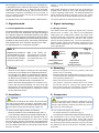
Die Signalbegriffe der Lichtsignale zeigt Abb. 1.
areas e. g. at the end of the station tracks and the branch
of sidings.
Stop signals should be as close to the end of the track as
possible, that is directly in front of the shunting limit signal
or at the beginning of the turnout. The distance between the
tracks should be at least 51 mm (H0), 37 mm (TT), 28 mm
(N) resp. 20 mm (Z) to allow sufcient space for the signal.
The signal shield have maintenance free LEDs.
3. Signal technology
3.1 Assign cables
The cables of the colour light stop signals have coloured
markers and a resistor. The cable of the white/yellow
LEDs (Sh1) has a white/yellow marker, the cable of the
red LEDs (Sh0) has a red marker. The cable with the black
marking and a diode instead of a resistor is the common
pole for all LEDs (positive pole). For more information re-
garding signals, please see Viessmann signal book, item
5299 – German language. Fig. 1 shows the aspects of the
colour light signals.
Sh0
„Halt! Fahrverbot!“
“Stop!
Driving prohibited!“
Sh1
„Fahrverbot
aufgehoben“
“Driving allowed“
Hinweis: Beim Vorbild wird
das Signalbild Sh1 mit wei
-
ßen Lampen dargestellt.
Unsere Modelle enthalten
weiße bzw. gelbe LEDs.
4. Einbau
- Nehmen Sie das Signal vorsichtig aus der Verpackung.
Führen Sie vor dem Einbau eine Funktionskontrolle durch.
- Dem Signal ist ein Etikett mit selbstklebenden Bezeich-
nungsschildern beigelegt. Schneiden Sie die gewünsch-
ten Bezeichnungsschilder aus und kleben Sie es nach
Abziehen der Schutzfolie auf den Signalkasten auf.
- Bohren Sie an der Montagestelle ein Loch (Ø 3,5 mm).
- Führen Sie die Anschlusskabel von oben durch das
Montageloch und stecken Sie dann das Signal mit dem
Steckfuß hinein. Falls erforderlich, Haltering von unten
auf den Steckfuß stecken.
5. Anschluss
Vorsicht:
Widerstände und Diode an den Enden der Anschlusska-
bel sind für die Funktion erforderlich. Keinesfalls entfer-
nen! Widerstände nicht mit Isolationsmaterial umhüllen,
da sonst keine ausreichende Kühlung möglich ist!
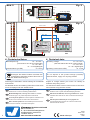
Sie können dieses Signal flexibel anschließen:
- Direkt per Schalter an einen Modellbahntrafo (Abb. 2).
- An ein Viessmann Steuermodul mit Tasten-Stellpult (Abb. 3).
Wir empfehlen die Verwendung des Steuermoduls, Art.
5221 und des Tasten-Stellpults, Art. 5547. Dann verfügt
das Signal über weichen Lichtwechsel und Zugbeeinflus-
sung. Für Digitalbetrieb eignen sich der Schaltdecoder, Art.
5213 für Märklin (Motorola) und der Multiprotokoll-Schalt-
decoder, Art. 5285.
4. Mounting
- Remove the signal from the box carefully. Check the
function prior to mounting.
- Adhesive labels are supplied with the signal. Simply cut
out the desired sign and attach it to the signal box after
removing the protection foil.
- Drill a hole (Ø 3.5 mm) at the mounting place.
- The signal‘s connection cables have to be insert-
ed into the hole first. Then put the signal with the
base socket into the hole. If necessary, screw the retain-
ing ring from the bottom onto the base socket.
5. Connection
Caution:
Resistors and diode at the cables are needed for proper
function of the lamp. Never cut them off! Never cover the
resistors with insulation material, because they have to
be cooled by surrounding air!
You can connect the signal very exible:
- Via switch directly to a transformer (fig. 2).
- To a Viessmann control module with push-button panel (fig. 3).
We recommend to use a control module, item 5221 and
the push-button panel, item 5547, which offer smooth
change of the lights and train control. For digital operation
we recommend the switching decoder, item 5213 for Mär-
klin (Motorola) and the multi protocol switching decoder,
item 5285.
LED rot
LED red
LED weiß/gelb
LED white/yellow
Hint: In the original, the
signal image Sh1 is shown
with white lamps. Our mod-
els contain white resp. yel-
low LEDs.

Modellbauartikel, kein Spielzeug! Nicht geeignet für
Kinder unter 14 Jahren! Anleitung aufbewahren!
Model building item, not a toy! Not suitable for children
under the age of 14 years! Keep these instructions!
Ce n’est pas un jouet! Ne convient pas aux enfants de moi-
ns de 14 ans! Conservez cette notice d’instructions!
Não é um brinquedo! Não aconselhável para menores de
14 anos! Conservar o manual de instruções!
Modelbouwartikel, geen speelgoed! Niet geschikt voor
kinderen onder 14 jaar! Gebruiksaanwijzing bewaren!
Articolo di modellismo, non è un giocattolo! Non adatto
a bambini al di sotto dei 14 anni! Conservare istruzioni per
l’uso!
Artículo para modelismo ¡No es un juguete! No
recomendado para menores de 14 años! Conserva las
instrucciones de servicio!
DE
EN
FR
NL
IT
ES
PT
Made in Europe
Viessmann
Modelltec
hnik GmbH
Bahnhofstraße 2a
D - 35116 Hatzfeld-Reddighausen
+49 6452 9340-0
www.viessmann-modell.de
4
Sekundär
0-10-16 V~
16 V
Primär
230 V~
Gefertigt nach
VDE 0570
EN 61558
Lichttransformator
5200
Nur für trockene Räume
Primär 230 V 50 - 60 Hz
Sekundär max. 3,25 A52 VA
ta 25°CIP 40
10 V
0 V
viessmann 5550
Universal-Ein-Aus-Umschalter
weiß / white
schwarz
black
gelb
z. B. / e. g. 5550
rot / red
z. B. / e. g. 5200
yellow
Diode
diode
Sekundär
0-10-16 V~
16 V
Primär
230 V~
Gefertigt nach
VDE 0570
EN 61558
Lichttransformator
5200
Nur für trockene Räume
Primär 230 V 50 - 60 Hz
Sekundär max. 3,25 A52 VA
ta 25°CIP 40
10 V
0 V
viessmann
Steuermodul für
Licht-Blocksignal
rt gn
Vorsignal -
Steuerung
zum Gleis
bn ge
16 V ~
5221
Tasten-Stellpult 2-begriffig
5547
Viessmann
braun / brown
rot / red
2 x schwarz / black
gelb / yellow
z. B.
5200
z. B.
5547
weiß / white
blau / blue
/ e. g.
/ e. g.
diode
Diode
Fig. 3
Abb. 3
Fig. 2
Abb. 2
98108
Stand 11/sw
12/2021
Ho/Kf
6. Technical data
Operating voltage: 10 – 16 V AC ~
(with and without item 5215, power module)
14 – 24 V DC =
13 – 24 V digital signal
Operating current (each LED): ca. 10 mA
6. Technische Daten
Betriebsspannung: 10 – 16 V AC ~
(mit und ohne Art. 5215, Powermodul)
14 – 24 V DC =
13 – 24 V Digitalsignal
Stromaufnahme (je LED): ca. 10 mA
Änderungen vorbehalten. Keine Haftung für Druckfehler
und Irrtümer.
Die aktuelle Version der Anleitung finden Sie auf der Viess-
mann Homepage unter der Artikelnummer.
Subject to change without prior notice. No liability for
mistakes and printing errors.
You will nd the latest version of the manual on the Viess-
mann website using the item number.
Entsorgen Sie dieses Produkt nicht über den
(unsortierten) Hausmüll, sondern führen Sie es
der Wiederverwertung zu.
Do not dispose of this product through (unsorted)
domestic waste, supply it to recycling instead.
-
 1
1
-
 2
2
-
 3
3
-
 4
4


in altre lingue
- English: Viessmann 4017 Owner's manual
- Deutsch: Viessmann 4017 Bedienungsanleitung
Documenti correlati
-
Viessmann 5210 Manuale del proprietario
-
-
-
Viessmann 5224 Manuale del proprietario
-
-
-
Viessmann 5221 Manuale del proprietario
-
-
-