
Bedienungsanleitung
Operation Manual
Innovation,
die bewegt!
5223
Steuermodul für Licht-
Ausfahrsignal
Control module for colour
light departure signal
1. Wichtige Hinweise / Important information ................................................ 2
2. Einleitung / Introduction ............................................................................. 2
3. Anschluss / Connection ............................................................................. 3
4. Steuermodul und Weiche / Control module and point ............................... 5
5. Digitale Ansteuerung / Digital control ......................................................... 6
6. Benutzung der Viessmann-Stecker / Using the Viessmann plugs ............. 6
7. Technische Daten / Technical data ............................................................ 7
AC
~
DC
=

2
1. Wichtige Hinweise
Bitte lesen Sie vor der ersten Anwendung des Produktes
bzw. dessen Einbau diese Bedienungsanleitung auf-
merksam durch. Bewahren Sie diese auf, sie ist Teil des
Produktes.
1.1 Sicherheitshinweise
Vorsicht:
Verletzungsgefahr!
Für die Montage sind Werkzeuge nötig.
Stromschlaggefahr!
Die Anschlussdrähte niemals in eine Steckdose einfüh-
ren! Verwendetes Versorgungsgerät (Transformator,
Netzteil) regelmäßig auf Schäden überprüfen. Bei Schä-
den am Versorgungsgerät dieses keinesfalls benutzen!
Alle Anschluss- und Montagearbeiten nur bei abgeschal
-
teter Betriebsspannung durchführen!
Ausschließlich nach VDE/EN gefertigte Modellbahn-
transformatoren verwenden!
Stromquellen unbedingt so absichern, dass es bei einem
Kurzschluss nicht zum Kabelbrand kommen kann.
1.2 Das Produkt richtig verwenden
Dieses Produkt ist bestimmt:
- Zum Einbau in Modelleisenbahnanlagen und Dioramen.
- Zum Anschluss an einen Modellbahntransformator
(z. B. Art. 5200) bzw. an eine Modellbahnsteuerung mit
zugelassener Betriebsspannung.
- Zum Betrieb in trockenen Räumen.
Jeder darüber hinausgehende Gebrauch gilt als nicht be-
stimmungsgemäß. Für daraus resultierende Schäden haftet
der Hersteller nicht.
1.3 Packungsinhalt überprüfen
Kontrollieren Sie den Lieferumfang auf Vollständigkeit:
- Steuermodul für Licht-Ausfahrsignal, Art. 5223
- 5 rote Stecker
- 4 gelbe Stecker
- 3 grüne Stecker
- 2 weiße Stecker
- 1 brauner Stecker
- 2 Schrauben
- Anleitung
2. Einleitung
Die Steuermodule für Lichtsignale, Art. 5220 bis 5224 von
Viessmann dienen der einfachen und vorbildgerechten
Ansteuerung aller Viessmann Standard-Lichtsignale.
Durch besondere Technik erfolgt der Wechsel zwischen
den einzelnen Signalbildern wie beim Vorbild fließend (die
LEDs glimmen nach). Die Signale werden direkt an die
Steuermodule angeschlossen.
Das Steuermodul für Licht-Ausfahrsignale, Art. 5223 wird
über Taster (z. B. Art. 5545 oder 5547), Gleiskontakte (z. B.
Art. 6840 für Baugröße H0) oder Schaltgleise angesteuert.
1. Important information
Please read this manual completely and attentively before
using the product for the first time. Keep this manual. It is
part of the product.
1.1 Safety instructions
Caution:
Risk of injury!
Tools are required for installation.
Electrical hazard!
Never put the connecting wires into a power socket!
Regularly examine the transformer for damage. In case
of any damage, do not use the transformer.
Make sure that the power supply is switched off when
you mount the device and connect the cables!
Only use VDE/EN tested special model train transform-
ers for the power supply!
The power sources must be protected to avoid the risk
of burning cables.
1.2 Using the product for its correct purpose
This product is intended:
- For installation in model train layouts and dioramas.
- For connection to an authorized model train transformer
(e. g. item 5200) or a digital command station.
- For operation in dry rooms only.
Using the product for any other purpose is not approved
and is considered inappropriate. The manufacturer is not
responsible for any damage resulting from the improper
use of this product.
1.3 Checking the package contents
Check the contents of the package for completeness:
- Control module for colour light departure signal, item 5223
- 5 red plugs
- 4 yellow plugs
- 3 green plugs
- 2 white plugs
- 1 brown plug
- 2 screws
- Manual
2. Introduction
The Viessmann control modules for colour light signals,
items 5220 to 5224 provide a simple and prototypical con-
trol of all Viessmann standard colour light signals. Special
technology enables prototypical transition between signal
aspects by first dimming and then turning off the LED with
subsequent soft start of the LED of the new signal aspect.
The signals are connected directly to the control modules.
The control module for colour light departure signals, item
5223 can be operated with push-button panels (e. g. item
5545 or 5547), track contacts (e. g. item 6840 for H0 gauge)
or switching tracks.

3
Über die Buchsen „Vorsignal-Steuerung“ kann ein Steuer-
modul (z. B. Art. 5220) für das zugehörige Vorsignal an-
gesteuert werden.
Für Licht-Ausfahrsignale, bei denen sich ein Licht-Vorsignal
mit am gleichen Mast befindet, benötigen Sie zusätzlich noch
das Steuermodul für Licht-Vorsignale, Art. 5220.
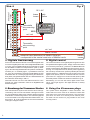
3. Anschluss
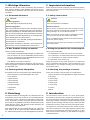
3.1 Anschluss von Versorgungsspannung
und Signal
Zur Spannungsversorgung ist das Modul über die oben links
liegenden Buchsen („bn“ und „ge“, d. h. braun und gelb) an
den 16 V-Wechselspannungsausgang eines Modellbahn-
transformators (z. B. Art. 5200) anzuschließen.
Das Lichtsignal wird an die unten am Steuermodul be-
findlichen, mit den Farben der entsprechenden Signal-
LEDs bezeichneten Buchsen angeschlossen.
Der gemeinsame Rückleiter des Lichtsignals (an dem sich
die Diode befindet) wird an die braune Buchse („bn“) des
Steuermoduls angeschlossen (= „Masse“).
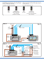
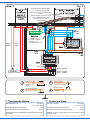
3.2 Abrufen der Signalbilder
Verwenden Sie zum Schalten der Signalbilder ein Tasten-
Stellpult (z. B. Art. 5545 oder 5547). Rückmeldefähige
Tasten-Stellpulte (z. B. Art. 5548 oder 5549) können nicht
verwendet werden! Die Ansteuerung ist auch durch Gleis-
kontakte (z. B. Art. 6840 für H0) oder Schaltgleise möglich
(Abb. 3).
A control module, item 5220 can be controlled via the sock-
ets “Vorsignal-Steuerung” for the corresponding colour light
distant signal.
Whenever a colour light distant signal is installed on the same
mast as the departure signal, an additional control module,
item 5220 for the colour light distant signal is required.
3. Connection
3.1 Connection of power supply and
signal
The upper left sockets (“bn” and “ge” – meaning brown
and yellow) have to be connected to the 16 V AC output of
a model train transformer (e. g. item 5200).
The colour light signal has to be connected with the sock-
ets located at the bottom of the control module. These
sockets are colour-coded with the corresponding colours
of the signal LEDs.
The common return conductor of the colour light signal
(where the diode is located) has to be connected to the
brown socket (“bn”) of the control module resp. the trans-
former (= “common ground”).
3.2 Activating the signal aspects
Use a push-button panel to switch the signal aspects
(e. g. items 5545 or 5547). Do not use push-button panels
with feedback (e. g. items 5548 or 5549)! Controlling is
also possible with track contacts (e. g. item 6840 for H0
gauge) or switching tracks (fig. 3).
Sekundär
0-10-16 V~
16 V
Primär
230 V~
Gefertigt nach
VDE 0570
EN 61558
Lichttransformator
5200
Nur für trockene Räume
Primär 230 V 50 - 60 Hz
Sekundär max. 3,25 A52 VA
ta 25°CIP 40
10 V
0 V
z. B. / e. g. 5200
braun / brown
gelb / yellow
rot / red gelb / yellow
weiß / whitegrün / green
Fig. 1
Abb. 1

4
Grundsätzlich ist zu beachten, dass immer gegen die
braune Betriebsspannungsleitung („bn“) des Signal-
moduls (= „Masse“) geschaltet wird.
Es ergeben sich folgende Signalbilder:
Please note that the contacts always have to be con-
nected to the brown pole (“bn”) of the signal module (=
“common ground”).
The possible signal aspects are:
16 V~AC
viessmann
5545
Stellpult fürAusfahrsignale
Hp0Hp1
Sh1 Hp2
rt1 ws
zum Gleis gn
Vorsignal -
Steuerung
rt2
viessmann
Steuermodul für
Licht-Ausfahrsignal 5223
16 V
bn ge
ge
blau / blue
braun
brown
gelb
yellow
Fig. 2
Abb. 2
rt1 ws
zum Gleis gn
Vorsignal -
Steuerung
rt2
viessmann
Steuermodul für
Licht-Ausfahrsignal 5223
16 V
bn ge
ge
5223
Signal
auf Hp0
(„Halt")
signal
shows Hp0
("stop")
Signal auf Hp2
(„Langsamfahrt")
signal shows Hp2
("
d")
proceed at reduced
spee
16 V~ AC
Schaltgleise oder
Gleiskontakte
(z. B. Art. 6840)
switching tracks or
track contacts
(e. g. item 6840)
Signal auf
Hp0 / Sh1
(„Rangierfahrt")
signal shows
Hp0 / Sh1
("shunting")
Signal auf Hp1
(„Fahrt")
signal shows
Hp1 ("proceed")
blau / blue
braun
brown
gelb
yellow
Fig. 3
Abb. 3
Hp0
„Halt“
“stop“
Hp2
„Langsamfahrt“
(max. 40 km/h)
“proceed at reduced speed“
(max. 40 km/h)
Hp1
„Fahrt“
“proceed“
Hp0 / Sh1
„Zughalt / Rangier-
verbot aufgehoben“
“stop / shunting
prohibition cancel ed„l
5223
z. B. / e. g.
5545

5
3.3 Anschluss der Vorsignal-
Steuerleitungen
Verbinden Sie die Buchsen „Vorsignal-Steuerung“ von Art.
5223 mit der grünen und gelben Eingangsbuchse am Steu-
ermodul, Art. 5220 des vorhergehenden Licht-Vorsignals
(Abb. 4).
3.3 Connection of the distant signal
control wires
Simply connect the sockets “Vorsignal-Steuerung” (=
“distant signal control”) of item 5223 with the green and
yellow input sockets of the control module, item 5220 of
the associated colour light distant signal (fig. 4).
4010, 4030,
4410, 4910 4013, 4413,
4913
Fig. 4
Abb. 4
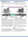
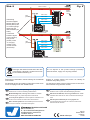
3.4 Zugbeeinussung
Die Signalsteuermodule sind mit einem Kontakt für die Zug
-
beeinflussung ausgestattet. Bei „Halt“-zeigendem Signal
(Hp0) kann damit der Strom am Gleis abgeschaltet werden,
sodass die Lokomotive vor dem Signal automatisch anhält.
Hierzu ist in einem Bereich von ca. 2 Lokomotivlängen vor
dem Signal ein Schienenprofil bzw. bei Märklin-Gleisen der
Mittelleiter mittels Isolierschienenverbindern Ihres Gleis-
systemherstellers (bzw. Mittelleiterisolierungen) elektrisch
zu trennen (siehe Abb. 6). In der Regel wird hierzu das
in Fahrtrichtung rechts liegende Schienenprofil gewählt.
Dieses Symbol neben dem Gleis kennzeichnet eine elekt-
rische Trennstelle (z. B. mit Isolierschienenverbindern) an
der gekennzeichneten Gleisseite. Bei Märklin-H0-Gleisen
entspricht dieses einer Mittelleiter-Trennstelle.
3.4 Automatic train control
Viessmann signal control modules are equipped with a
contact for automatic train control. When the signal shows
the “stop” aspect (Hp0) the track in front of the signal is
disconnected and the locomotive stops automatically.
To achieve this you must electrically isolate a track
section (or the centre rail contacts of the Märklin tracks)
of approx. 2 locomotive lengths in front of the signal
by means of insulating rail connectors matching your
track system (or insulate the centre rail contacts).
Usually the right hand track (in direction of travel) is
insulated (see fig. 6).
This sign next to the track designates an electrical track
insulation (e. g. with insulating track connectors) at the
marked side of the track. For Märklin H0 tracks, this is a
neutral conductor disconnecting point.
4. Steuermodul und Weiche
Das Signalbild Hp2 („Langsamfahrt“) wird geschaltet, wenn
mindestens eine der folgenden Weichen auf „abzweigen“
gestellt ist. Abb. 7 zeigt, wie Steuermodul und Weiche
gemeinsam geschaltet werden können.
4. Control module and point
The signal has to show the Hp2 aspect (“proceed at re-
duced speed”) if minimum one of the following turnouts is
set to “branch off”. Fig. 7 shows how you can switch the
control module and the point together.

6
Fahrstrom
traction
current
ca. 2 Loklängen
approx. 2 locomotive lengths
direction of
travel
entspricht dem Mittelleiter bei Märklin-Schienen
corresponds to the of M rklin tracksneutral conductor ä
N2
Fahrtrichtung
Trennstelle
disconnecting
5223
16 V~AC
rt1 ws
zum Gleis gn
Vorsignal -
Steuerung
rt2
viessmann
Steuermodul für
Licht-Ausfahrsignal 5223
16 V
bn ge
ge
point
Trennstelle
disconnecting
point
braun
brown
gelb
yellow
rot / red
rot / red
rot / red
braun / brown
Fig. 6
Abb. 6
5. Digitale Ansteuerung
Sie können das Steuermodul für Licht-Ausfahrsignale auch
mit einem Digitalsystem über einen Magnetartikeldecoder
(z. B. Art. 5211 für Märklin-Motorola-Format oder Art. 5280
für das NMRA- und DCC-Format) ansteuern (Abb. 8). Wich-
tig ist, dass der Magnetartikeldecoder positive Schaltimpul-
se liefert (d. h. er schaltet gegen „+“)! Außerdem muss bei
Art. 5211 eine Verbindung zwischen Digital-Masse (braun)
und Masse der 16 V-Versorgungsspannung des Steuermo-
duls (braun) hergestellt werden. Bei Art. 5280 beachten Sie
die markierte Verbindung in Abb. 8.
Alternativ können sie auch das Steuermodul für Licht-
Signale, Art. 5224 verwenden. Dort ist ein Digitaldecoder
bereits integriert!
6. Benutzung der Viessmann-Stecker
Das obenstehende Symbol kennzeichnet eine Leitungs-
verbindung. Die sich hier kreuzenden Leitungen müssen
an einer beliebigen Stelle ihres Verlaufs elektrisch leitend
miteinander in Verbindung stehen. Der Verbindungspunkt
muss nicht exakt an der eingezeichneten Stelle sitzen, son-
dern kann z. B. zu einem Stecker an einer der kreuzenden
Leitungen verlagert werden.
5. Digital control
The control module for colour light departure signals can also
be operated with a digital system. Simply connect the cables
to an accessory decoder (e. g. item 5211 for Märklin-Motorola
format or item 5280 for the NMRA and DCC format). Also re-
fer to fig. 8. It is important to know, that the pulses supplied by
the accessory decoder have positive potential (the decoder
switches against “+”)! With item 5211 the common pole of the
digital circuit (brown) must be connected with the common
pole of the 16 V supply for the control module (brown). With
item 5280 please consider the marked connection in fig. 8.
Alternatively you can use item 5224, digital control mod-
ule for colour light signals. The digital decoder is already
integrated!
6. Using the Viessmann plugs
The symbol above designates a cable connection. The
cables that cross here must be in electrical contact with
each other at any point along their length. The connection
point does not have to be exactly at the marked point,
but rather can be moved to a plug located at one of the
crossing cables.

7
Schaltgleise oder Gleiskontakte
(z. B. Art. 6840) schalten das
Signal automatisch zurück auf Hp0
(”Halt”)
Switching tracks or track contacts
(e. g. item 6840) switch the
signal back to Hp0 (”stop”)
automatically
1 A Dioden (z. B.
Art. 6834, 10 Stück)
1 A diodes (e. g.
item 6834, 10 pieces)
traction current
rot
red
braun
brown
braun / brown
gelb / yellow
rot / red
gelb / yellow
weiß / white
grün / green
blau
blue
Fig. 7
Abb. 7
34
1
2
Litzen verdrillen
Twist wires together
Kabel abisolieren
ca. 1,5 cm
Stecker aufschieben
Push plug on
Draht umbiegen
Dismantle the
cable
Bend wire
7. Technische Daten
Betriebsspannung: 16 V AC~
14 – 24 V DC=
Stromaufnahme (ohne Signal): 5 mA
Stromaufnahme im Schaltmoment: 50 mA
Geeignet für LED-Lichtsignale mit gemeinsamer Anode
(Plus-Pol).
7. Technical data
Operating voltage: 16 V AC~
14 – 24 V DC=
Operating current (without signal): 5 mA
Operating current at switching moment: 50 mA
Suitable for light signals with LED and common anode
(positive pole).

Änderungen vorbehalten. Keine Haftung für Druckfehler
und Irrtümer.
Die aktuelle Version der Anleitung finden Sie auf der Viess-
mann Homepage unter der Artikelnummer.
Subject to change without prior notice. No liability for
mistakes and printing errors.
You will find the latest version of the manual on the Viess-
mann website using the item number.
Entsorgen Sie dieses Produkt nicht über den
(unsortierten) Hausmüll, sondern führen Sie
es der Wiederverwertung zu.
Do not dispose of this product through (unsorted)
domestic waste, supply it to recycling instead.
Modellbauartikel, kein Spielzeug! Nicht geeignet für
Kinder unter 14 Jahren! Anleitung aufbewahren!
Model building item, not a toy! Not suitable for children
under the age of 14 years! Keep these instructions!
Ce n’est pas un jouet! Ne convient pas aux enfants de moi-
ns de 14 ans! Conservez cette notice d’instructions!
Não é um brinquedo! Não aconselhável para menores de
14 anos! Conservar o manual de instruções!
Modelbouwartikel, geen speelgoed! Niet geschikt voor
kinderen onder 14 jaar! Gebruiksaanwijzing bewaren!
Articolo di modellismo, non è un giocattolo! Non adatto
a bambini al di sotto dei 14 anni! Conservare istruzioni per
l’uso!
Artículo para modelismo ¡No es un juguete! No
recomendado para menores de 14 años! Conserva las
instrucciones de servicio!
DE
EN
FR
NL
IT
ES
PT
Made in Europe
Viessmann
Modelltec
hnik GmbH
Bahnhofstraße 2a
D - 35116 Hatzfeld-Reddighausen
+49 6452 9340-0
www.viessmann-modell.de
digital
traction
current
blau / blue
blau / blue
blau / blue
blau / blue
gelb
yellow
braun / brown
rot / red
Fig. 8
Abb. 8
92074
Stand 06/sw
07/2021
Ho/Kf
Verbindung
zwischen Digital-
Masse (braun) und
Masse (braun) der
16 V-Versorgungs-
spannung des
Steuermoduls (Art.
5223).
Connection
between digital
ground (brown)
and ground
(brown) of the
16 V supply
voltage of the
control module
(item 5223).
digital
traction
current
5280
blau / blue
blau / blue
blau / blue
blau / blue
gelb
yellow
braun / brown
rot / red
-
 1
1
-
 2
2
-
 3
3
-
 4
4
-
 5
5
-
 6
6
-
 7
7
-
 8
8


in altre lingue
- English: Viessmann 5223 Owner's manual
- Deutsch: Viessmann 5223 Bedienungsanleitung
Documenti correlati
-
Viessmann 5221 Manuale del proprietario
-
Viessmann 5224 Manuale del proprietario
-
Viessmann 5222 Manuale del proprietario
-
-
-
-
-
-
-