Cameo OTOS® SP6 Manuale utente
- Categoria
- Proiettori
- Tipo
- Manuale utente

USER´S MANUAL
BEDIENUNGSANLEITUNG
MANUEL D`UTILISATION
MANUAL DE USUARIO
INSTRUKCJA OBSŁUGI
MANUALE D‘ USO
OTOS® SP6
OUTDOOR LED MOVING HEAD
CLOTOSSP6
ANIMATION WHEEL

CONTENTS / INHALTSVERZEICHNIS / CONTENU / CONTENIDO / TREŚĆ /
CONTENUTO
ENGLISH
INFORMATION ON THIS USER MANUAL 6
INTENDED USE 6
DEFINITIONS AND SYMBOL EXPLANATIONS 6
SAFETY INSTRUCTIONS 7
NOTES ON PORTABLE OUTDOOR DEVICES 10
INCLUDED 11
INTRODUCTION 11
CONNECTIONS, OPERATING AND DISPLAY ELEMENTS 12
OPERATION 15
SETUP AND INSTALLATION 29
CARE, MAINTENANCE AND REPAIR 29
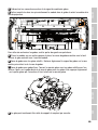
REPLACING GOBOS 30
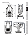
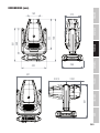
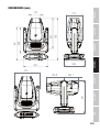
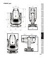
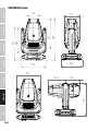
DIMENSIONS 33
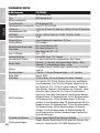
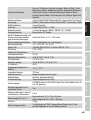
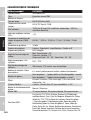
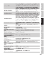
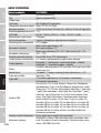
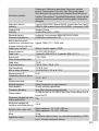
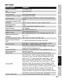
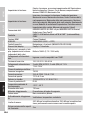
TECHNICAL DATA 34
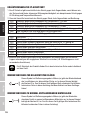
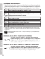
EXPLANATION OF IP PROTECTION CLASS 36
MINIMUM DISTANCE TO ILLUMINATED SURFACE 36
MINIMUM DISTANCE TO NORMALLY FLAMMABLE MATERIALS 36
DISPOSAL 37
MANUFACTURER’S DECLARATIONS 37
DEUTSCH
INFORMATIONEN ZU DIESER BEDIENUNGSANLEITUNG 39
BESTIMMUNGSGEMÄSSER GEBRAUCH 39
BEGRIFFS- UND SYMBOLERKLÄRUNGEN 39
SICHERHEITSHINWEISE 40
HINWEISE FÜR ORTSVERÄNDERLICHE OUTDOOR-GERÄTE 44
LIEFERUMFANG 44
EINFÜHRUNG 44
ANSCHLÜSSE, BEDIEN- UND ANZEIGEELEMENTE 45
BEDIENUNG 48
AUFSTELLUNG UND MONTAGE 62
PFLEGE, WARTUNG UND REPARATUR 62
GOBOS AUSTAUSCHEN 64
ABMESSUNGEN 67
TECHNISCHE DATEN 68
ERLÄUTERUNGEN ZUR IP-SCHUTZART 70

MINDESTABSTAND ZUR BELEUCHTETEN FLÄCHE 70
MINDESTABSTAND ZU NORMAL ENTFLAMMBAREN MATERIALIEN 70
ENTSORGUNG 71
HERSTELLERERKLÄRUNGEN 71
FRANÇAIS
INFORMATIONS SUR CE MANUEL D’UTILISATION 72
UTILISATION PRÉVUE 72
DÉFINITIONS ET EXPLICATION DES PICTOGRAMMES 72
CONSIGNES DE SÉCURITÉ 73
NOTES SUR LES APPAREILS PORTABLES POUR EXTÉRIEUR 77
CONTENU DU CARTON 77
INTRODUCTION 77
BRANCHEMENTS, UTILISATION ET INDICATEURS 78
FONCTIONNEMENT 81
MONTAGE ET INSTALLATION 96
ENTRETIEN, MAINTENANCE ET RÉPARATIONS 97
REMPLACEMENT DES GOBOS 98
DIMENSIONS 101
CARACÉRISTIQUES TECHNIQUES 102
EXPLICATION DE LA CLASSE DE PROTECTION IP 104
DISTANCE MINIMALE PAR RAPPORT À LA SURFACE ÉCLAIRÉE 105
DISTANCE MINIMALE PAR RAPPORT AUX MATÉRIAUX NORMALEMENT INFLAMMABLES 105
MISE AU REBUT 105
DÉCLARATIONS DU FABRICANT 106
ESPAÑOL
INFORMACIÓN SOBRE ESTE MANUAL DEL USUARIO 107
USO PREVISTO 107
DEFINICIONES Y EXPLICACIONES DE LOS SÍMBOLOS 107
INSTRUCCIONES DE SEGURIDAD 108
NOTAS SOBRE LOS DISPOSITIVOS PORTÁTILES DE EXTERIOR 112
CONTENIDO DE LA ENTREGA 112
INTRODUCCIÓN 112
CONEXIONES, MANDOS E INDICADORES 113
FUNCIONAMIENTO 116
CONFIGURACIÓN E INSTALACIÓN 130

CUIDADO, MANTENIMIENTO Y REPARACIÓN 131
SUSTITUCIÓN DE GOBOS 132
DIMENSIONES 135
DATOS TÉCNICOS 136
EXPLICACIÓN DE LA CLASE DE PROTECCIÓN IP 138
DISTANCIA MÍNIMA A LA SUPERFICIE ILUMINADA 139
DISTANCIA MÍNIMA A MATERIALES NORMALMENTE INFLAMABLES 139
RECICLAJE 139
DECLARACIONES DEL FABRICANTE 140
POLSKI
INFORMACJE NA TEMAT NINIEJSZEJ INSTRUKCJI OBSŁUGI 141
ZAMIERZONE ZASTOSOWANIE 141
DEFINICJE I OBJAŚNIENIA SYMBOLI 141
INSTRUKCJE BEZPIECZEŃSTWA 142
UWAGI DOTYCZĄCE PRZENOŚNYCH URZĄDZEŃ ZEWNĘTRZNYCH 146
ZAKRES DOSTAWY 146
WPROWADZENIE 146
PRZYŁĄCZA, ELEMENTY OBSŁUGI I WSKAŹNIKI 147
OBSŁUGA 150
KONFIGURACJA I INSTALACJA 164
PIELĘGNACJA, KONSERWACJA I NAPRAWA 164
WYMIANA GOBOSÓW 166
WYMIARY 169
DANE TECHNICZNE 170
WYJAŚNIENIE KLASY OCHRONY IP 172
MINIMALNA ODLEGŁOŚĆ OD OŚWIETLANEJ POWIERZCHNI 172
MINIMALNA ODLEGŁOŚĆ OD MATERIAŁÓW NORMALNIE ŁATWOPALNYCH 172
UTYLIZACJA 173
DEKLARACJE PRODUCENTA 173
ITALIANO
INFORMAZIONI SU QUESTO MANUALE DI ISTRUZIONI 174
USO PREVISTO 174
DEFINIZIONI E SPIEGAZIONI DEI SIMBOLI 174
ISTRUZIONI DI SICUREZZA 175
NOTE SUI DISPOSITIVI PORTATILI PER ESTERNI 178

MATERIALE COMPRESO NELLA FORNITURA 179
INTRODUZIONE 179
CONNESSIONI, ELEMENTI DI COMANDO E DI VISUALIZZAZIONE 180
FUNZIONAMENTO 183
INSTALLAZIONE E CONFIGURAZIONE 197
CURA, MANUTENZIONE E RIPARAZIONE 198
SOSTITUZIONE DEI GOBOS 199
DIMENSIONI 202
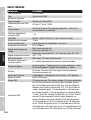
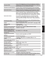
DATI TECNICI 203
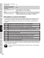
SPIEGAZIONE DELLA CLASSE DI PROTEZIONE IP 205
DISTANZA MINIMA DALLA SUPERFICIE ILLUMINATA 205
DISTANZA MINIMA DAI MATERIALI NORMALMENTE INFIAMMABILI 206
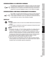
SMALTIMENTO 206
DICHIARAZIONI DEL PRODUTTORE 206
DMX
DMX CONTROL / DMX STEUERUNG / PILOTAGE DMX /
CONTROL DMX / STEROWANIE DMX / CONTROLLO DMX 208

6
DMX
ITALIANO
POLSKI
ESPAÑOL
FRANCAIS
DEUTSCHENGLISH
ENGLISH
You have made the right choice!
This device has been developed and manufactured to the highest quality standards to ensure
many years of problem-free operation. Please read this user manual carefully to be able to use
your new Cameo product quickly and optimally. Further information about Cameo Light is availab-
le on our website CAMEOLIGHT.COM.
INFORMATION ON THIS USER MANUAL
• Carefully read the safety instructions and the entire manual before operating the device.
• Observe the warnings on the device and in the user manual.
• Always keep the user manual within reach.
• If you sell or pass on the device, it is important that you also include this user manual, as it is an
integral part of the product.
INTENDED USE
The product is a device for event technology!
This product has been developed for professional use in the field of event technology and is not
suitable for use as domestic lighting!
Furthermore, this product is only intended for qualified users with specialist knowledge of event
technology!
Use of the product outside the specified technical data and operating conditions is considered
improper use!
Liability for damage and third-party damage to persons and property due to inappropriate use is
excluded!
The product is not suitable for:
• Use by persons (including children) with limited physical, sensory or mental abilities or lack of
experience and knowledge.
• Children (children must be instructed not to play with the device).
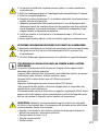
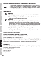
DEFINITIONS AND SYMBOL EXPLANATIONS
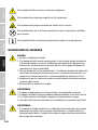
1. DANGER: The word DANGER, possibly in combination with a symbol, indicates immediately
dangerous situations or conditions for life and limb.
2. WARNING: The word WARNING, possibly in combination with a symbol, indicates potentially
dangerous situations or conditions for life and limb.
3. CAUTION: The word CAUTION, possibly in combination with a symbol, is used to indicate situa-
tions or conditions that may lead to injury.
4. ATTENTION: The word ATTENTION, possibly in combination with a symbol, refers to situations
or states that can lead to damage to property and/or the environment.
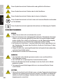
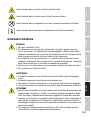
This symbol identifies hazards that can cause electric shock.
This symbol identifies hazardous areas or hazardous situations.

7
DMX DEUTSCHFRANCAIS
ESPAÑOL ENGLISH
ITALIANO POLSKI
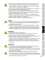
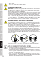
This symbol indicates hazards caused by hot surfaces.
This symbol indicates hazards caused by intense light sources.
This symbol indicates a device in which there are no user-replaceable parts.
This symbol indicates additional information on the operation of the product.
SAFETY INSTRUCTIONS
HAZARD:
1. Do not open or modify the unit.
2. If your device no longer functions properly, if liquids or objects get inside it or if it
has been damaged in any other way, switch it off immediately and disconnect it
from the mains. The device may be repaired only by authorised repair technicians.
3. For devices of protection class 1, the protective conductor must be connected
correctly. Never disconnect the protective conductor. Devices of protection class 2
do not have a protective conductor.
4. Ensure that live cables are not kinked or otherwise mechanically damaged.
5. Never bypass the unit fuse.
WARNING:
1. The device may not be operated if it shows obvious signs of damage.
2. The device may only be installed in a voltage-free state.
3. If the mains cable of the device is damaged, do not operate the device.
4. Permanently connected power cables may only be replaced by a qualified person.
ATTENTION:
1. Do not operate the unit if it has been exposed to large temperature fluctuations
(for example, after transport). Moisture and condensation can damage the device.
Switch on the device only when it has reached room temperature.
2. Make sure that the voltage and frequency of the mains supply correspond to the
values indicated on the unit. If the device has a voltage selector switch, do not
connect the device until it has been set correctly. Use only suitable power cables.
3. To disconnect the unit from the mains at all poles, it is not sufficient to press the
on/off switch on the unit.
4. Make sure that the fuse used corresponds to the type printed on the unit.

8
DMX
ITALIANO
POLSKI
ESPAÑOL
FRANCAIS
DEUTSCHENGLISH
5. Make sure that appropriate measures have been taken against overvoltage (e.g.
lightning strike).
6. Observe the specified maximum output current on units with Power Out connec-
tion. Ensure that the total current consumption of all connected devices does not
exceed the specified value.
7. Replace pluggable mains cables only with original cables.
HAZARD:
1. Danger of suffocation! Plastic bags and small parts must be kept out of reach of
persons (including children) with reduced physical, sensory or mental capabilities.
2. Danger from falling down! Make sure that the device is securely installed and will
not fall down. Only use suitable stands or mounts (particularly for fixed installa-
tions). Ensure that accessories are properly installed and secured. Ensure that
applicable safety regulations are observed.
WARNING:
1. Use the device only in the manner intended.
2. Operate the device only with the accessories recommended and intended by the
manufacturer.
3. During installation, observe the safety regulations applicable in your country.
4. After connecting the unit, check all cable routes to avoid damage or accidents, e.g.
due to tripping hazards.
5. Always observe the specified minimum distance to normally flammable materials!
Unless explicitly stated, the minimum distance is 0.3 m.
6. Always observe the minimum distance to the illuminated surface that can be read
on the device!
CAUTION:
1. In the case of moving components such as mounting brackets or other moving
components, there is a possibility of jamming.
2. In the case of units with motor-driven components, there is a risk of injury from the
movement of the unit. Sudden movement of the device can cause shock reactions.
3. The housing surface of the device can become very hot during regular operation.
Ensure that accidental touching of the housing is not possible. Always allow the
lamp to cool sufficiently before removal, maintenance work and charging etc.
ATTENTION:
1. Do not install or operate the device near any radiators, heat registers, stoves or other
heat sources. Ensure that the device is always installed in such a way that it is suffi-
ciently cooled and cannot overheat.
2. Do not place ignition sources such as burning candles near the device.
3. Ventilation openings must not be covered and fans must not be blocked.

9
DMX DEUTSCHFRANCAIS
ESPAÑOL ENGLISH
ITALIANO POLSKI
4. Use the original packaging or packaging provided by the manufacturer for transport.
5. Avoid shock or impact to the unit.
6. Observe the IP protection class as well as the ambient conditions such as tempera-
ture and humidity according to the specification.
7. Devices can be constantly further developed. In the event of deviating information on
operating conditions, performance or other device properties between the user manual
and the device labelling, the information on the device always takes priority.
8. The unit is not suitable for tropical climates and for operation above 2000 m above
sea level.
9. Unless explicitly stated, the unit is not suitable for operation in marine conditions .
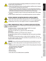
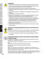
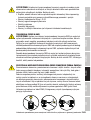
CAUTION! IMPORTANT INFORMATION REGARDING LIGHTING PRODUCTS!
1. Never look directly into the beam of light, not even for a short period of time.
2. Never look into the beam of light using optical devices such as a magnifying glass.
3. Stroboscopic effects may cause epileptic seizures in susceptible individuals!
SIGNAL TRANSMISSION BY RADIO (E.G. W-DMX OR AUDIO RADIO SYSTEMS):
The quality and performance of wireless signal transmissions generally depends on
the ambient conditions.
The following factors can impact range and signal stability, for example:
Shielding (e.g. masonry, metal structures, water)
High volume of radio traffic (e.g. powerful wireless LAN networks)
Interference
Electromagnetic radiation (e.g. LED video screens, dimmers)
All range specifications refer to free-field application with visual contact and without
interference!
The operation of transmission systems is subject to official regulations. These may
vary from region to region and must be checked by the operator before use (e.g. radio
frequency and transmission power).
WARNING: Devices with wireless signal transmission are not suitable for use in sen-
sitive areas in which radio operation can lead to potential detrimental effects. These
include:
• Hospitals, health centres or other healthcare facilities that provide patient treatment
with skilled personnel and equipment.
• Hazardous areas Class I, II and III
• Restricted areas
• Military facilities
• Aircraft or vehicles
• Areas where the use of mobile phones is prohibited

10
DMX
ITALIANO
POLSKI
ESPAÑOL
FRANCAIS
DEUTSCHENGLISH
TRANSMISSION VIA W-DMX
WARNING: In general, wireless DMX transmission must not be used for applications
involving safety-related factors that might result in personal injury or property dama-
ge in the event of a failure.
This applies in particular to moving scene or traverse structures, DMX-controlled mo-
tors/lifts or lifting devices for operating DMX-operated platform lifts, hydraulic systems
or comparable moving components.
Furthermore, wireless DMX transmission must not be used to trigger flame or pyro-
technic devices, explosion-driven effects, or to control gas or liquid effects. These
include CO2 cannons, confetti shooters, water effects or similar.
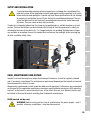
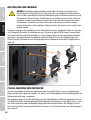
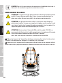
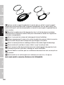
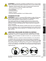
CAUTION! POTENTIAL DAMAGE FROM EXTERNAL LIGHT SOURCES!
Solar radiation, laser radiation and bundled light beams from other spotlights can da-
mage the housing and internal components such as filters, gobo and colour wheels,
motors, cables, belts, etc., as well as light sources!
Do not expose the unit and especially the lens opening to direct sunlight, laser radi-
ation and bundled light beams from other spotlights during unpacking, installation,
prolonged non-use and operation! Always point the lens opening towards the floor
when the unit is not in use! For this purpose, also use the Sun Protection function,
which can be activated via DMX command (see Device Settings channel in the DMX
table). An integrated gyroscope sensor detects the position of use.
Damage caused by external light sources is excluded from the manufacturer's warranty!
NOTES ON PORTABLE OUTDOOR DEVICES
1. Temporary operation! Event equipment is generally only designed for temporary
operation.
2. Continuous operation or permanent structural installation – particularly outdoors –
can impair the function, surfaces and seals and accelerate material fatigue.
3. Damage to the surface coating can impair the device's corrosion protection.
Damaged surface coating (e.g. scratches) must be promptly repaired by suitable
measures.

11
DMX DEUTSCHFRANCAIS
ESPAÑOL ENGLISH
ITALIANO POLSKI
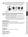
INCLUDED
Remove the product from the packaging and remove all packaging material.
Please check the completeness and integrity of the delivery and notify your distribution partner
immediately after purchase if the delivery is not complete or if it is damaged.
The packaging includes:
X 1 x OTOS SP6 Moving Head
X 1x Power cord
X 2 x Omega bracket
X User manual
INTRODUCTION
PROFESSIONAL OUTDOOR LED MOVING HEAD
CLOTOSSP6
CONTROL FUNCTIONS:
33, 36 and 50 channel DMX control
Master/slave operation
Standalone operation
W-DMX™
FEATURES:
Protection class IP65. 600 W LED. DMX512. W-DMX™. Artnet and sACN. 5-pin DMX connections.
2x Omega mounting brackets included. Operating voltage: 100–240 V AC.
The spotlight features the RDM standard (Remote Device Management). This remote device
management enables the status query and configuration of RDM end devices via an RDM-capable
controller, such as the optionally available Cameo UNICON (item number CLIREMOTE).

12
DMX
ITALIANO
POLSKI
ESPAÑOL
FRANCAIS
DEUTSCHENGLISH
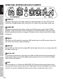
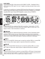
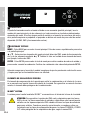
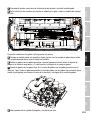
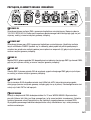
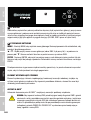
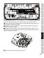
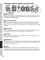
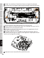
CONNECTIONS, OPERATING AND DISPLAY ELEMENTS
1 POWER IN
IP65 power input socket with rubber sealing cap. Operating voltage 100–240 V AC/50–60 Hz.
Connection via supplied power cable (when not in use, always close with rubber sealing cap).
2 POWER OUT
IP65 power output socket with rubber sealing cap. Facilitates power supply to other CAMEO
spotlights. Ensure that the total current consumption of all connected devices does not exceed
the value specified on the device in amperes (A) (when not in use, always close with the rubber
sealing cap).
3 DMX IN
Male IP65 5-pin XLR socket for connecting a DMX control device (e.g. DMX console; when not in
use, always close with the rubber sealing cap).
4 DMX OUT
Female IP65 5-pin XLR socket for sending DMX control signal (when not in use, always close with
the rubber sealing cap).
5 NET IN / OUT
RJ45 network connections for connecting to an ArtNet or sACN network and for forwarding the
control signal (always close with the rubber sealing cap when not in use). Use CAT 5e or better
cables to set up the network.
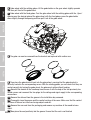
6 FUSE
IP65 fuse holder for 5 x 20mm fuses. IMPORTANT NOTE: Replace the fuse only with one of the
same type and rating. Carefully close the fuse holder again so that the IP65 tightness is still gua-
ranteed. In the event of repeated fuse failure, please contact an authorised service centre.
1 2 3 4
56

13
DMX DEUTSCHFRANCAIS
ESPAÑOL ENGLISH
ITALIANO POLSKI
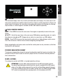
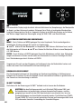
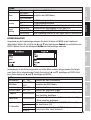
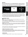
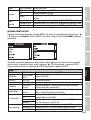
7 LC DISPLAY
The illuminated display shows the currently activated mode (main display), the menu items in the
main menu and sub-menus and the numerical value or status in certain menu items. If there is no
control signal to the device, the characters in the centre of the display start flashing; the flashing
stops as soon as a control signal is available (W-DMX, DMX and slave operation).
8 TOUCH-SENSITIVE CONTROLS
MENU – Press MENU to access the main menu. Press again or repeatedly to return to the main
display.
and – Select the menu items in the main menu (DMX address, operating mode, etc.) and in
the submenus using and . Change value or status in a menu item, e.g. DMX address.
ENTER – Press ENTER to access the menu level to make value or status changes, and to access
one of the sub-menus. Confirm value or status changes by pressing ENTER.
Before navigating the unit menu, make sure that the control panels are dry and clean so that their
functionality is not impaired.
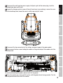
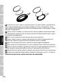
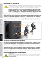
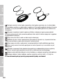
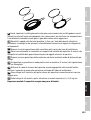
PRESSURE EQUALISATION ELEMENT
The pressure compensation element to prevent condensation inside the housing is located in the
rear part of the unit head. In order to ensure its proper function, the element must be protected
from contamination.
W-DMX™ ANTENNA
The antenna for control via W-DMX™ is located inside the unit base.
ATTENTION: To ensure IP65 splash protection for the DMX and network sockets,
the special input and output sockets must be correctly sealed with the IP65 special
plugs or the rubber sealing caps must be used for sealing. When connected correct-
ly, or when sealed correctly with the rubber sealing caps, the POWER IN and POWER
OUT sockets are protected from spraying water, as in accordance with IP65.
8
7

14
DMX
ITALIANO
POLSKI
ESPAÑOL
FRANCAIS
DEUTSCHENGLISH
The battery-powered display can be activated, even if the device is not connected to
the mains. To do this, press and hold MENU for about 10 seconds. You can now access
device information to change and save system settings without mains connection.
External control of the spotlight is not activated in this case. For this reason, the display
shows that there is no DMX signal even if a DMX signal is available at the device.
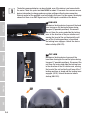
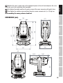
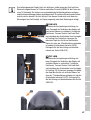
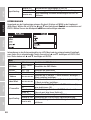
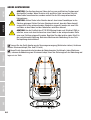
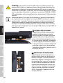
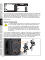
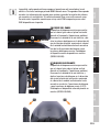
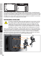
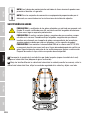
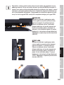
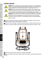
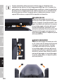
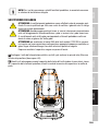
9 PAN LOCK
Mechanical locking device to prevent the head
from turning on the horizontal plane during
transport (8 possible positions). Disconnect
the unit from the mains and slide the locking
lever in the direction of the pan rotation axis,
moving the head of the unit horizontally until
one of the 8 locking positions is found and
the locking lever engages. Unlock the device
before startup (UNLOCK).
10 TILT LOCK
Mechanical locking device to prevent the
head from turning on the vertical plane during
transport (7 possible positions). Disconnect the
unit from the mains and slide the locking lever
in the direction of the tilt rotation axis, moving
the head of the unit vertically until one of the 7
locking positions is found and the locking lever
engages (LOCK). Unlock the device before
startup (UNLOCK).
10
UNLOCK
LOCK
9
UNLOCKLOCK
11 11

15
DMX DEUTSCHFRANCAIS
ESPAÑOL ENGLISH
ITALIANO POLSKI
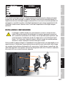
11 RECESSED GRIPS
In addition to the two transport handles on the base of the unit, there are practical recessed grips
at the top of the inner sides of the two device arms.
OPERATION
NOTES
Once the fixture is correctly connected to the mains, the display will show "Software
Update ...please wait", the software version, "Welcome to Cameo" and "...RESET"
during the start-up procedure and motor reset. After this process, the spotlight is
ready for operation and the previously activated operating mode is launched. The
main display is activated automatically if no input is made within approximately 30
seconds.
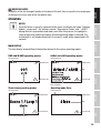
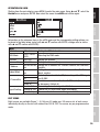
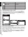
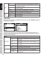
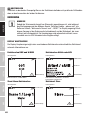
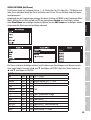
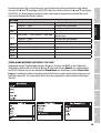
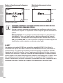
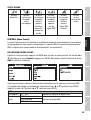
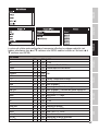
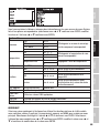
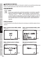
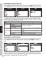
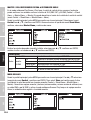
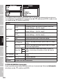
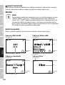
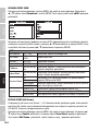
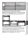
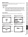
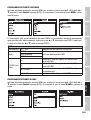
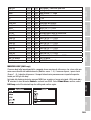
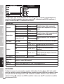
MAIN DISPLAY
The main display shows different information relevant to the various operating modes.
DMX and W-DMX operating modes ArtNet and sACN operating modes
LED-Temperature
W-DMX Status
Error Message
DMX-Starting Address and DMX-Mode
LED-Temperature
W-DMX Status
Error Message
Mode
DMX-Mode, DMX-Address, IP-Adress, Subnet
Mask and Galaxy
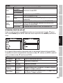
Stand-alone operating modes Operating mode Slave
LED-Temperature
W-DMX Status
Error Message
Scene / Loop and Signal Output
LED-Temperature
W-DMX Status
Error Message
Mode

16
DMX
ITALIANO
POLSKI
ESPAÑOL
FRANCAIS
DEUTSCHENGLISH
NOTE REGARDING THE MAIN DISPLAY IN OPERATING MODES WITH EXTERNAL
CONTROL:
As soon as the control signal is interrupted, the characters in the centre of the display
begin to flash. The flashing stops when a control signal is present.
Error message: If the warning symbol (triangle with exclamation mark) appears in
the display, there is an error in one or more components of the unit. Which compo-
nents are affected can be seen in the System Info Menu under Error Info. If the
error cannot be rectified by a restart or reset, please contact an authorised service
centre.
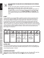
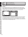
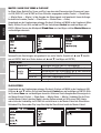
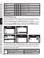
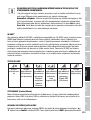
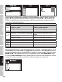
W-DMX™
To pair a W-DMX receiver with a W-DMX compatible transmitter, the Reset command must be
executed in the menu item WDMX under Receiver (select and confirm Reset). The receiver is
now in pairing standby and waiting for a pairing request from a transmitter. Start the pairing
by selecting Link in the menu of the transmitter and confirming; the pairing now takes place
automatically. In the same way, several receivers can be paired simultaneously or one after the
other to a transmitter (e.g. for master/slave operation). A W-DMX connection is always maintained
until the connection is disconnected by means of the Reset command in the receiver or the Unlink
command in the transmitter, regardless of whether a device has been disconnected from the
power supply in the meantime.
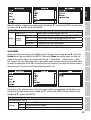
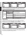
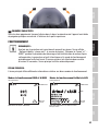
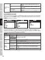
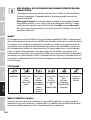
W-DMX™ STATUS
?
W-DMX
deactivated
W-DMX
as receiver
activated,
not paired
W-DMX
as receiver
activated and
paired,
Transmitter
switched off
or out of
range
W-DMX
as receiver
activated and
paired,
no
DMX signal
W-DMX
as receiver
activated and
paired,
DMX signal
is present
W-DMX
as transmitter
activated,
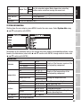
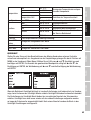
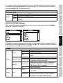
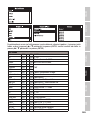
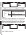
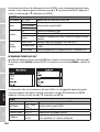
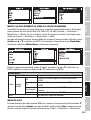
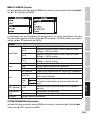
CONTROL MENU
The control menu enables selection of the various operating modes and their setting options in
the relevant sub-menus. DMX address and DMX operating mode are set in each operating mode
across all operating modes, if relevant.
OPERATION VIA DMX CABLE
Starting from the main display, press MENU to enter the main menu. Using and , select the
Control menu and press ENTER. Now select the DMX menu item and confirm again.

17
DMX DEUTSCHFRANCAIS
ESPAÑOL ENGLISH
ITALIANO POLSKI
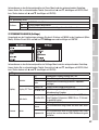
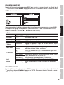
Information on the submenu items in the DMX menu and the corresponding setting options can be
found in the table below (select with and confirm with ENTER, change value or status with
and confirm with ENTER).
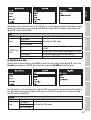
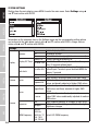
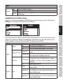
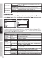
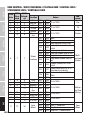
DMX
DMX Address 001 - 4xx Setting the DMX start address
Mode
33CH Basic
Selecting the DMX mode36CH Standard
50CH Extended
W-DMX Trans-
mitter
Off Deactivate sending of the DMX control signal via
W-DMX
On Activate DMX control signal forwarding via W-DMX
Force to pair Pairing with ready-to-pair W-DMX devices
Unlink All Disconnect all W-DMX connections
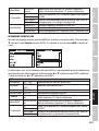
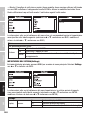
OPERATION VIA W-DMX
Starting from the main display, press MENU to enter the main menu. Using and , select the
Control menu and press ENTER. Now select the menu item W-DMX and confirm again.
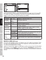
For information on the submenu items in the W-DMX menu and the corresponding setting options,
see the table below (select with and confirm with ENTER, change value or status with
and confirm with ENTER).
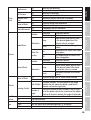
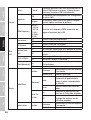
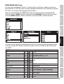
W-DMX
DMX Address 001 - 4xx Setting the DMX start address
Mode
33CH Basic
Selecting the DMX mode36CH Standard
50CH Extended

18
DMX
ITALIANO
POLSKI
ESPAÑOL
FRANCAIS
DEUTSCHENGLISH
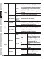
Receive
Off Deactivate W-DMX reception
On Activate W-DMX reception
Unlink Disconnect W-DMX connections and put them in coupling standby
Signal
routing
Send to XLR Forwarding the control signal to XLR (DMX OUT)
Backup by XLR Control via XLR (DMX IN) with W-DMX signal interruption
Receive only No connection between W-DMX signal and XLR connectors
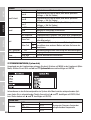
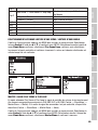
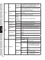
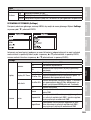
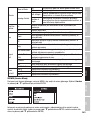
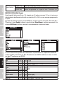
OPERATION VIA ART-NET
Starting from the main display, press MENU to enter the main menu. Using and , select the
Control menu and press ENTER. Now select the menu item ArtNet and confirm again.
Information on the submenu items in the ArtNet menu and the corresponding setting options can
be found in the table below (select with and confirm with ENTER, change value or status
with and confirm with ENTER).
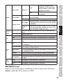
ArtNet
DMX Address 001 - 4xx Setting the DMX start address
DMX Mode 33CH / 36CH /
50CH Selecting the DMX mode
Universe 000–255 Setting the universe
Universe Group 000–127 Setting the Universe Group
IP Address xxx.xxx.xxx.
xxx.xxx
Setting the IP address: Set 1st block, confirm, Set 2nd block,
confirm..
Subnet Mask xxx.xxx.xxx.
xxx.xxx
Setting the subnet mask: Set 1st block, confirm, Set 2nd
block, confirm..
W-Transmitter
On Activate (On) or deactivate (Off) forwarding of the DMX signal
via W-DMX.
Off
Force to pair Establish a connection with other W-DMX units (Force to
pair) or disconnect them (Unlink all).
Unlink all
Signal Routing
Send to XLR Forwarding the control signal to XLR Out
Backup by XLR Control via XLR with ArtNet signal interruption
Receive only No connection between network signal and XLR connectors

19
DMX DEUTSCHFRANCAIS
ESPAÑOL ENGLISH
ITALIANO POLSKI
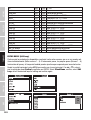
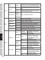
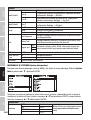
OPERATION VIA SACN
Starting from the main display, press MENU to enter the main menu. Using and , select the
Control menu and press ENTER. Now select the menu item sACN and confirm again.
Information on the submenu items in the sACN menu and the corresponding setting options can
be found in the table below (select with and confirm with ENTER, change value or status
with and confirm with ENTER).
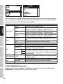
sACN
DMX Address 001 - 4xx Setting the DMX start address
DMX Mode 33CH / 36CH /
50CH Selecting the DMX mode
Universe 000–255 Setting the universe
Universe Group 000–127 Setting the Universe Group
IP Address xxx.xxx.xxx.xxx.
xxx
Setting the IP address: Set 1st block, confirm, Set 2nd block,
confirm..
Subnet Mask xxx.xxx.xxx.xxx.
xxx
Setting the subnet mask: Set 1st block, confirm, Set 2nd
block, confirm..
W-Transmitter
On Activate (On) or deactivate (Off) forwarding of the DMX signal
via W-DMX.
Off
Force to pair Establish a connection with other W-DMX units (Force to pair)
or disconnect (Unlink all).
Unlink all
Signal Routing
Send to XLR Forwarding the control signal to XLR Out
Backup by XLR Control via XLR with ArtNet signal interruption
Receive only No connection between network signal and XLR connectors
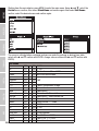
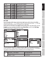
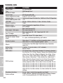
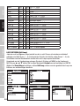
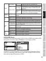
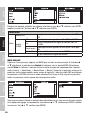
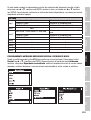
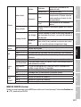
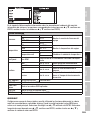
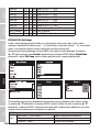
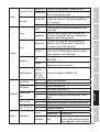
EDIT SCENE
Eight scenes are available (Scene 1 - 8). Set pan, tilt, gobo, pan / tilt macros etc. of each scene
individually directly on the unit with values from 000 to 255. The scenes are pre-programmed ex
works.

20
DMX
ITALIANO
POLSKI
ESPAÑOL
FRANCAIS
DEUTSCHENGLISH
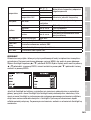
Starting from the main display, press MENU to enter the main menu. Using and , select the
Control menu, confirm, then select Stand Alone and confirm again. Now select Edit Scene,
confirm, select the desired scene and confirm again.
The scene is activated when confirmed and you can make the settings as desired (see table,
select with and confirm with ENTER, change value or status with and confirm with
ENTER).
Edit Scene
Pan 000 – 255 0-100
Tilt 000 – 255 0-100
Dimmer 000 – 255 Master dimmer 0% -> 100%
Strobe 000 – 255 Multi-functional strobe
Cyan 000 – 255
CMYMagenta 000 – 255
Yellow 000 – 255
CTO 000 – 255 Colour Transmission Orange
Colour wheel 000 – 255 Colour wheel
Gobo 000 – 255 Gobo wheel 1
Gobo rot. 000 – 255 Gobo wheel 1 Gobo rotation
red Fine 000 – 255 Gobo wheel 1 Gobo rotation fine
Gobo2 000 – 255 Gobo wheel 2
Zoomz 000 – 255 Zoom narrow <-> wide
Focus 000 – 255 0-100
Iris 000 – 255 0-100
Prism 000 – 255 Prism
Prism red. 000 – 255 (Prism rotation)
Frost1 000 – 255 Frost 1 0% <-> 100%
Frost2 000 – 255 Frost 2 0% <-> 100%
Animation 000 – 255 Animation wheel
La pagina si sta caricando...
La pagina si sta caricando...
La pagina si sta caricando...
La pagina si sta caricando...
La pagina si sta caricando...
La pagina si sta caricando...
La pagina si sta caricando...
La pagina si sta caricando...
La pagina si sta caricando...
La pagina si sta caricando...
La pagina si sta caricando...
La pagina si sta caricando...
La pagina si sta caricando...
La pagina si sta caricando...
La pagina si sta caricando...
La pagina si sta caricando...
La pagina si sta caricando...
La pagina si sta caricando...
La pagina si sta caricando...
La pagina si sta caricando...
La pagina si sta caricando...
La pagina si sta caricando...
La pagina si sta caricando...
La pagina si sta caricando...
La pagina si sta caricando...
La pagina si sta caricando...
La pagina si sta caricando...
La pagina si sta caricando...
La pagina si sta caricando...
La pagina si sta caricando...
La pagina si sta caricando...
La pagina si sta caricando...
La pagina si sta caricando...
La pagina si sta caricando...
La pagina si sta caricando...
La pagina si sta caricando...
La pagina si sta caricando...
La pagina si sta caricando...
La pagina si sta caricando...
La pagina si sta caricando...
La pagina si sta caricando...
La pagina si sta caricando...
La pagina si sta caricando...
La pagina si sta caricando...
La pagina si sta caricando...
La pagina si sta caricando...
La pagina si sta caricando...
La pagina si sta caricando...
La pagina si sta caricando...
La pagina si sta caricando...
La pagina si sta caricando...
La pagina si sta caricando...
La pagina si sta caricando...
La pagina si sta caricando...
La pagina si sta caricando...
La pagina si sta caricando...
La pagina si sta caricando...
La pagina si sta caricando...
La pagina si sta caricando...
La pagina si sta caricando...
La pagina si sta caricando...
La pagina si sta caricando...
La pagina si sta caricando...
La pagina si sta caricando...
La pagina si sta caricando...
La pagina si sta caricando...
La pagina si sta caricando...
La pagina si sta caricando...
La pagina si sta caricando...
La pagina si sta caricando...
La pagina si sta caricando...
La pagina si sta caricando...
La pagina si sta caricando...
La pagina si sta caricando...
La pagina si sta caricando...
La pagina si sta caricando...
La pagina si sta caricando...
La pagina si sta caricando...
La pagina si sta caricando...
La pagina si sta caricando...
La pagina si sta caricando...
La pagina si sta caricando...
La pagina si sta caricando...
La pagina si sta caricando...
La pagina si sta caricando...
La pagina si sta caricando...
La pagina si sta caricando...
La pagina si sta caricando...
La pagina si sta caricando...
La pagina si sta caricando...
La pagina si sta caricando...
La pagina si sta caricando...
La pagina si sta caricando...
La pagina si sta caricando...
La pagina si sta caricando...
La pagina si sta caricando...
La pagina si sta caricando...
La pagina si sta caricando...
La pagina si sta caricando...
La pagina si sta caricando...
La pagina si sta caricando...
La pagina si sta caricando...
La pagina si sta caricando...
La pagina si sta caricando...
La pagina si sta caricando...
La pagina si sta caricando...
La pagina si sta caricando...
La pagina si sta caricando...
La pagina si sta caricando...
La pagina si sta caricando...
La pagina si sta caricando...
La pagina si sta caricando...
La pagina si sta caricando...
La pagina si sta caricando...
La pagina si sta caricando...
La pagina si sta caricando...
La pagina si sta caricando...
La pagina si sta caricando...
La pagina si sta caricando...
La pagina si sta caricando...
La pagina si sta caricando...
La pagina si sta caricando...
La pagina si sta caricando...
La pagina si sta caricando...
La pagina si sta caricando...
La pagina si sta caricando...
La pagina si sta caricando...
La pagina si sta caricando...
La pagina si sta caricando...
La pagina si sta caricando...
La pagina si sta caricando...
La pagina si sta caricando...
La pagina si sta caricando...
La pagina si sta caricando...
La pagina si sta caricando...
La pagina si sta caricando...
La pagina si sta caricando...
La pagina si sta caricando...
La pagina si sta caricando...
La pagina si sta caricando...
La pagina si sta caricando...
La pagina si sta caricando...
La pagina si sta caricando...
La pagina si sta caricando...
La pagina si sta caricando...
La pagina si sta caricando...
La pagina si sta caricando...
La pagina si sta caricando...
La pagina si sta caricando...
La pagina si sta caricando...
La pagina si sta caricando...
La pagina si sta caricando...
La pagina si sta caricando...
La pagina si sta caricando...
La pagina si sta caricando...
La pagina si sta caricando...
La pagina si sta caricando...
La pagina si sta caricando...
La pagina si sta caricando...
La pagina si sta caricando...
La pagina si sta caricando...
La pagina si sta caricando...
La pagina si sta caricando...
La pagina si sta caricando...
La pagina si sta caricando...
La pagina si sta caricando...
La pagina si sta caricando...
La pagina si sta caricando...
La pagina si sta caricando...
La pagina si sta caricando...
La pagina si sta caricando...
La pagina si sta caricando...
La pagina si sta caricando...
La pagina si sta caricando...
La pagina si sta caricando...
La pagina si sta caricando...
La pagina si sta caricando...
La pagina si sta caricando...
La pagina si sta caricando...
La pagina si sta caricando...
La pagina si sta caricando...
La pagina si sta caricando...
La pagina si sta caricando...
La pagina si sta caricando...
La pagina si sta caricando...
La pagina si sta caricando...
La pagina si sta caricando...
La pagina si sta caricando...
La pagina si sta caricando...
La pagina si sta caricando...
La pagina si sta caricando...
La pagina si sta caricando...
La pagina si sta caricando...
La pagina si sta caricando...
La pagina si sta caricando...
La pagina si sta caricando...
-
 1
1
-
 2
2
-
 3
3
-
 4
4
-
 5
5
-
 6
6
-
 7
7
-
 8
8
-
 9
9
-
 10
10
-
 11
11
-
 12
12
-
 13
13
-
 14
14
-
 15
15
-
 16
16
-
 17
17
-
 18
18
-
 19
19
-
 20
20
-
 21
21
-
 22
22
-
 23
23
-
 24
24
-
 25
25
-
 26
26
-
 27
27
-
 28
28
-
 29
29
-
 30
30
-
 31
31
-
 32
32
-
 33
33
-
 34
34
-
 35
35
-
 36
36
-
 37
37
-
 38
38
-
 39
39
-
 40
40
-
 41
41
-
 42
42
-
 43
43
-
 44
44
-
 45
45
-
 46
46
-
 47
47
-
 48
48
-
 49
49
-
 50
50
-
 51
51
-
 52
52
-
 53
53
-
 54
54
-
 55
55
-
 56
56
-
 57
57
-
 58
58
-
 59
59
-
 60
60
-
 61
61
-
 62
62
-
 63
63
-
 64
64
-
 65
65
-
 66
66
-
 67
67
-
 68
68
-
 69
69
-
 70
70
-
 71
71
-
 72
72
-
 73
73
-
 74
74
-
 75
75
-
 76
76
-
 77
77
-
 78
78
-
 79
79
-
 80
80
-
 81
81
-
 82
82
-
 83
83
-
 84
84
-
 85
85
-
 86
86
-
 87
87
-
 88
88
-
 89
89
-
 90
90
-
 91
91
-
 92
92
-
 93
93
-
 94
94
-
 95
95
-
 96
96
-
 97
97
-
 98
98
-
 99
99
-
 100
100
-
 101
101
-
 102
102
-
 103
103
-
 104
104
-
 105
105
-
 106
106
-
 107
107
-
 108
108
-
 109
109
-
 110
110
-
 111
111
-
 112
112
-
 113
113
-
 114
114
-
 115
115
-
 116
116
-
 117
117
-
 118
118
-
 119
119
-
 120
120
-
 121
121
-
 122
122
-
 123
123
-
 124
124
-
 125
125
-
 126
126
-
 127
127
-
 128
128
-
 129
129
-
 130
130
-
 131
131
-
 132
132
-
 133
133
-
 134
134
-
 135
135
-
 136
136
-
 137
137
-
 138
138
-
 139
139
-
 140
140
-
 141
141
-
 142
142
-
 143
143
-
 144
144
-
 145
145
-
 146
146
-
 147
147
-
 148
148
-
 149
149
-
 150
150
-
 151
151
-
 152
152
-
 153
153
-
 154
154
-
 155
155
-
 156
156
-
 157
157
-
 158
158
-
 159
159
-
 160
160
-
 161
161
-
 162
162
-
 163
163
-
 164
164
-
 165
165
-
 166
166
-
 167
167
-
 168
168
-
 169
169
-
 170
170
-
 171
171
-
 172
172
-
 173
173
-
 174
174
-
 175
175
-
 176
176
-
 177
177
-
 178
178
-
 179
179
-
 180
180
-
 181
181
-
 182
182
-
 183
183
-
 184
184
-
 185
185
-
 186
186
-
 187
187
-
 188
188
-
 189
189
-
 190
190
-
 191
191
-
 192
192
-
 193
193
-
 194
194
-
 195
195
-
 196
196
-
 197
197
-
 198
198
-
 199
199
-
 200
200
-
 201
201
-
 202
202
-
 203
203
-
 204
204
-
 205
205
-
 206
206
-
 207
207
-
 208
208
-
 209
209
-
 210
210
-
 211
211
-
 212
212
-
 213
213
-
 214
214
-
 215
215
-
 216
216


Cameo OTOS® SP6 Manuale utente
- Categoria
- Proiettori
- Tipo
- Manuale utente
in altre lingue
- français: Cameo OTOS® SP6 Manuel utilisateur
- español: Cameo OTOS® SP6 Manual de usuario
- Deutsch: Cameo OTOS® SP6 Benutzerhandbuch
- polski: Cameo OTOS® SP6 Instrukcja obsługi
Documenti correlati
-
Cameo OTOS® H5 Manuale utente
-
-
-
-
-
-
-
-
-
