
USER´S MANUAL
BEDIENUNGSANLEITUNG
MANUEL D`UTILISATION
MANUAL DE USUARIO
INSTRUKCJA OBSŁUGI
MANUALE D‘ USO
G4 FC
GALLERY LIGHT WITH RGBL LED
CLG4FC / CLG4FCWH

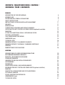
CONTENTS / INHALTSVERZEICHNIS / CONTENU /
CONTENIDO / TREŚĆ / CONTENUTO
ENGLISH
INFORMATION ON THIS USER MANUAL 6
INTENDED USE 6
DEFINITIONS AND SYMBOL EXPLANATIONS 6
SAFETY INSTRUCTIONS 7
INSTRUCTIONS FOR INDOOR INSTALLATION EQUIPMENT 11
INCLUDED 11
INTRODUCTION 11
CONNECTIONS, OPERATING AND DISPLAY ELEMENTS 12
OPERATION PER UNIT CONTROLLER CAMEO UNICON (optionally available) 14
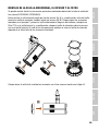
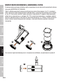
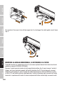
MOUNTING 22
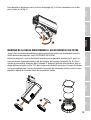
FITTING THE DIRECTIONAL GRILLE, DIFFUSER AND FILTER 23
OPTIONAL ACCESSORIES 24
CARE, MAINTENANCE AND REPAIR 24
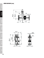
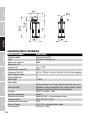
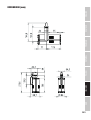
DIMENSIONS (mm) 25
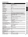
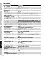
TECHNICAL DATA 26
MINIMUM DISTANCE TO ILLUMINATED SURFACE 27
MINIMUM DISTANCE TO NORMALLY FLAMMABLE MATERIALS 27
DISPOSAL 27
MANUFACTURER’S DECLARATIONS 28
DEUTSCH
INFORMATIONEN ZU DIESER BEDIENUNGSANLEITUNG 29
BESTIMMUNGSGEMÄSSER GEBRAUCH 29
BEGRIFFS- UND SYMBOLERKLÄRUNGEN 29
SICHERHEITSHINWEISE 30
HINWEISE FÜR INDOOR-INSTALLATIONSGERÄTE 34
LIEFERUMFANG 34
EINFÜHRUNG 35
ANSCHLÜSSE, BEDIEN- UND ANZEIGEELEMENTE 36
BEDIENUNG PER UNIT CONTROLLER CAMEO UNICON (optional erhältlich) 38
MONTAGE 46
RICHTGITTER, STREUSCHEIBE UND FILTER MONTIEREN 47
OPTIONALES ZUBEHÖR 48
PFLEGE, WARTUNG UND REPARATUR 49
ABMESSUNGEN (mm) 50
TECHNISCHE DATEN 51

MINDESTABSTAND ZUR BELEUCHTETEN FLÄCHE 52
MINDESTABSTAND ZU NORMAL ENTFLAMMBAREN MATERIALIEN 52
ENTSORGUNG 52
HERSTELLERERKLÄRUNGEN 53
FRANÇAIS
INFORMATIONS SUR CE MANUEL D'UTILISATION 54
UTILISATION PRÉVUE 54
DÉFINITIONS ET EXPLICATION DES PICTOGRAMMES 54
CONSIGNES DE SÉCURITÉ 55
INSTRUCTIONS POUR L'INSTALLATION DE L'APPAREIL EN INTÉRIEUR 59
CONTENU DU CARTON 59
INTRODUCTION 60
BRANCHEMENTS, UTILISATION ET INDICATEURS 61
UTILISATION AVEC CONTRÔLEUR CAMEO UNICON (disponible en option) 63
MONTAGE 72
MONTAGE DE LA GRILLE DIRECTIONNELLE, DU DIFFUSEUR ET DU FILTRE 73
ACCESSOIRES EN OPTION 74
ENTRETIEN, MAINTENANCE ET RÉPARATIONS 74
DIMENSIONS (mm) 75
CARACÉRISTIQUES TECHNIQUES 76
DISTANCE MINIMALE PAR RAPPORT À LA SURFACE ÉCLAIRÉE 77
DISTANCE MINIMALE PAR RAPPORT AUX MATÉRIAUX NORMALEMENT INFLAMMABLES 77
MISE AU REBUT 78
DÉCLARATIONS DU FABRICANT 78
ESPAÑOL
INFORMACIÓN SOBRE ESTE MANUAL DEL USUARIO 80
USO PREVISTO 80
DEFINICIONES Y EXPLICACIONES DE LOS SÍMBOLOS 80
INSTRUCCIONES DE SEGURIDAD 81
NOTAS PARA LOS EQUIPOS QUE SE INSTALAN EN INTERIORES 85
CONTENIDO DEL EMBALAJE 86
INTRODUCCIÓN 86
CONEXIONES, MANDOS E INDICADORES 87
FUNCIONAMIENTO POR UNIDAD CONTROLADOR CAMEO UNICON (disponible opcionalmente) 89
MONTAJE 97

MONTAJE DE LA REJILLA DIRECCIONAL, EL DIFUSOR Y EL FILTRO 99
ACCESORIOS OPCIONALES 100
CUIDADO, MANTENIMIENTO Y REPARACIÓN 100
DIMENSIONES (mm) 101
DATOS TÉCNICOS 102
DISTANCIA MÍNIMA A LA SUPERFICIE ILUMINADA 103
DISTANCIA MÍNIMA A MATERIALES NORMALMENTE INFLAMABLES 103
RECICLAJE 103
DECLARACIÓN DEL FABRICANTE 104
POLSKI
INFORMACJE NA TEMAT NINIEJSZEJ INSTRUKCJI OBSŁUGI 105
ZAMIERZONE ZASTOSOWANIE 105
DEFINICJE I OBJAŚNIENIA SYMBOLI 105
INSTRUKCJE BEZPIECZEŃSTWA 106
INSTRUKCJE DLA URZĄDZEŃ MONTOWANYCH W POMIESZCZENIACH 110
ZAWARTOŚĆ OPAKOWANIA 110
WPROWADZENIE 111
PRZYŁĄCZA, ELEMENTY OBSŁUGI I WSKAŹNIKI 112
OPERACJA NA JEDNOSTCE STERUJĄCEJ CAMEO UNICON (opcja) 114
MOCOWANIE 122
MONTAŻ KRATKI KIERUNKOWEJ, NAWIEWNIKA I FILTRA 124
AKCESORIA OPCJONALNE 125
PIELĘGNACJA, KONSERWACJA I NAPRAWA 125
WYMIARY (mm) 126
DANE TECHNICZNE 127
MINIMALNA ODLEGŁOŚĆ OD OŚWIETLANEJ POWIERZCHNI 128
MINIMALNA ODLEGŁOŚĆ OD MATERIAŁÓW NORMALNIE ŁATWOPALNYCH 128
UTYLIZACJA 128
DEKLARACJE PRODUCENTA 129
ITALIANO
INFORMAZIONI SU QUESTO MANUALE DI ISTRUZIONI 130
USO PREVISTO 130
DEFINIZIONI E SPIEGAZIONI DEI SIMBOLI 130
ISTRUZIONI DI SICUREZZA 131
ISTRUZIONI PER LE APPARECCHIATURE DA INSTALLARE IN INTERNI 135

CONTENUTO DEL L’IMBALLAGGIO 135
INTRODUZIONE 136
CONNESSIONI, ELEMENTI DI COMANDO E DI VISUALIZZAZIONE 137
FUNZIONAMENTO PER UNITÀ CONTROLLER CAMEO UNICON (disponibile come opzione) 139
MONTAGGIO 147
MONTARE LA GRIGLIA DIREZIONALE, IL DIFFUSORE E IL FILTRO 148
ACCESSORI OPZIONALI 149
CURA, MANUTENZIONE E RIPARAZIONE 150
DIMENSIONI (mm) 151
DATI TECNICI 152
DISTANZA MINIMA DALLA SUPERFICIE ILLUMINATA 153
DISTANZA MINIMA DA MATERIALI NORMALMENTE INFLAMMABILI 153
SMALTIMENTO 153
DICHIARAZIONI DEL PRODUTTORE 154
DMX CONTROL / DMX STEUERUNG / PILOTAGE DMX /
CONTROL DMX / STEROWANIE DMX / CONTROLLO DMX 155

6
DMX
ITALIANO
POLSKI
ESPAÑOL
FRANCAIS
DEUTSCHENGLISH
ENGLISH
You have made the right choice!
This device has been developed and manufactured to the highest quality standards to ensure
many years of problem-free operation. Please read this user manual carefully to be able to use
your new Cameo product quickly and optimally. Further information about Cameo Light is availab-
le on our website CAMEOLIGHT.COM.
INFORMATION ON THIS USER MANUAL
• Carefully read the safety instructions and the entire manual before operating the device.
• Observe the warnings on the device and in the user manual.
• Always keep the user manual within reach.
• If you sell or pass on the device, it is important that you also include this user manual, as it is an
integral part of the product.
INTENDED USE
This product is a spotlight for permanent installation!
This spotlight is intended exclusively for professional users and is not suitable for private house-
holds or third parties!
Use of the product outside the specified technical data and operating conditions, as well as incor-
rect installation, is considered inappropriate!
Liability for damage and third-party damage to persons and property due to inappropriate use is
excluded!
The product is not suitable for:
• Use by persons (including children) with limited physical, sensory or mental abilities or lack of
experience and knowledge.
• Children (children must be instructed not to play with the device).
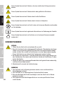
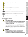
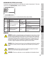
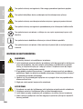
DEFINITIONS AND SYMBOL EXPLANATIONS
1. DANGER: The word DANGER, possibly in combination with a symbol, indicates immediately
dangerous situations or conditions for life and limb.
2. WARNING: The word WARNING, possibly in combination with a symbol, indicates potentially
dangerous situations or conditions for life and limb.
3. CAUTION: The word CAUTION, possibly in combination with a symbol, is used to indicate situa-
tions or conditions that may lead to injury.
4. ATTENTION: The word ATTENTION, possibly in combination with a symbol, refers to situations
or states that can lead to damage to property and/or the environment.
This symbol identifies hazards that can cause electric shock.

7
DMX DEUTSCHFRANCAIS
ESPAÑOL ENGLISH
ITALIANO POLSKI
This symbol identifies hazardous areas or hazardous situations.
This symbol indicates hazards caused by hot surfaces.
This symbol indicates hazards caused by intense light sources.
This symbol indicates a device in which there are no user-replaceable parts.
This symbol indicates additional information on the operation of the product.
This symbol indicates a device that may only be used in dry rooms.
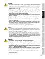
SAFETY INSTRUCTIONS
HAZARD:
1. Do not open or modify the unit.
2. If your device no longer functions properly, if liquids or objects get inside it or if it
has been damaged in any other way, switch it off immediately and disconnect it
from the mains. The device may be repaired only by authorised repair technicians.
3. For devices of protection class 1, the protective conductor must be connected
correctly. Never disconnect the protective conductor. Devices of protection class 2
do not have a protective conductor.
4. Ensure that live cables are not kinked or otherwise mechanically damaged.
5. Never bypass the appliance fuse.
WARNING:
1. The device may not be operated if it shows obvious signs of damage.
2. The device may only be installed in a voltage-free state.
3. If the mains cable of the device is damaged, do not operate the device.
4. Permanently connected power cables may only be replaced by a qualified person.
ATTENTION:
1. Do not operate the unit if it has been exposed to large temperature fluctuations
(for example, after transport). Moisture and condensation can damage the device.
Switch on the device only when it has reached room temperature.

8
DMX
ITALIANO
POLSKI
ESPAÑOL
FRANCAIS
DEUTSCHENGLISH
2. Make sure that the voltage and frequency of the mains supply correspond to the
values indicated on the unit. If the device has a voltage selector switch, do not
connect the device until it has been set correctly. Use only suitable power cables.
3. To disconnect the unit from the mains at all poles, it is not sufficient to press the
on/off switch on the unit.
4. Make sure that the fuse used corresponds to the type printed on the unit.
5. Make sure that appropriate measures have been taken against overvoltage (e.g.
lightning strike).
6. Observe the specified maximum output current on units with Power Out connec-
tion. Ensure that the total current consumption of all connected devices does not
exceed the specified value.
7. Replace pluggable mains cables only with original cables.
HAZARD:
1. Danger of suffocation! Plastic bags and small parts must be kept out of reach of
persons (including children) with reduced physical, sensory or mental capabilities.
2. Danger from falling down! Make sure that the device is securely installed and will
not fall down. Only use suitable stands or mounts (particularly for fixed installa-
tions). Ensure that accessories are properly installed and secured. Ensure that
applicable safety regulations are observed.
WARNING:
1. Use the device only in the manner intended.
2. Operate the device only with the accessories recommended and intended by the
manufacturer.
3. During installation, observe the safety regulations applicable in your country.
4. After connecting the unit, check all cable routes to avoid damage or accidents, e.g.
due to tripping hazards.
5. Always observe the specified minimum distance to normally flammable materials!
Unless explicitly stated, the minimum distance is 0.3 m.
6. Always observe the minimum distance to the illuminated surface that can be read
on the device!
CAUTION:
1. In the case of moving components such as mounting brackets or other moving
components, there is a possibility of jamming.
2. In the case of units with motor-driven components, there is a risk of injury from the
movement of the unit. Sudden movement of the device can cause shock reactions.
3. The housing surface of the device can become very hot during regular operation.
Ensure that accidental touching of the housing is not possible. Always allow the
lamp to cool sufficiently before removal, maintenance work and charging etc.

9
DMX DEUTSCHFRANCAIS
ESPAÑOL ENGLISH
ITALIANO POLSKI
ATTENTION:
1. Do not install or operate the device near any radiators, heat registers, stoves or
other heat sources. Ensure that the device is always installed in such a way that it
is sufficiently cooled and cannot overheat.
2. Do not place ignition sources such as burning candles near the device.
3. Ventilation openings must not be covered and fans must not be blocked.
4. Use the original packaging or packaging provided by the manufacturer for transport.
5. Avoid shock or impact to the unit.
6. Observe the IP protection class as well as the ambient conditions such as tempera-
ture and humidity according to the specification.
7. Devices can be constantly further developed. In the event of deviating informati-
on on operating conditions, performance or other device properties between the
user manual and the device labelling, the information on the device always takes
priority.
8. The unit is not suitable for tropical climates and for operation above 2000 m above
sea level.
9. Unless explicitly stated, the unit is not suitable for operation in marine conditions .
For conversion or retrofit sets or accessories provided by the manufacturer, it is
essential to observe the instructions included.
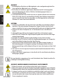
CAUTION! IMPORTANT INFORMATION REGARDING LIGHTING PRODUCTS!
1. Never look directly into the beam of light, not even for a short period of time.
2. Never look into the beam of light using optical devices such as a magnifying glass.
3. Stroboscopic effects may cause epileptic seizures in susceptible individuals!
4. Permanently installed lamps are built into these lighting units. These may not
be replaced by the user. The lamps contained in this lighting unit may only be
replaced by the manufacturer, its service partner, or a similarly qualified person.
SIGNAL TRANSMISSION BY RADIO (e.g. W-DMX or audio radio systems):
The quality and performance of wireless signal transmissions generally depends on
the ambient conditions. The following factors can impact range and signal stability,
for example:
Shielding (e.g. masonry, metal structures, water)
High volume of radio traffic (e.g. powerful wireless LAN networks)
Interference
Electromagnetic radiation (e.g. LED video screens, dimmers)

10
DMX
ITALIANO
POLSKI
ESPAÑOL
FRANCAIS
DEUTSCHENGLISH
All range specifications refer to free-field application with visual contact and without
interference!
The operation of transmission systems is subject to official regulations. These may
vary from region to region and must be checked by the operator before use (e.g. radio
frequency and transmission power).
WARNING: Devices with wireless signal transmission are not suitable for use in sen-
sitive areas in which radio operation can lead to potential detrimental effects. These
include:
• Hospitals, health centres or other healthcare facilities that provide patient treat-
ment with skilled personnel and equipment.
• Hazardous areas Class I, II and III
• Restricted areas
• Military facilities
• Aircraft or vehicles
• Areas where the use of mobile phones is prohibited
TRANSMISSION VIA W-DMX
WARNING: In general, wireless DMX transmission must not be used for applications
involving safety-related factors that might result in personal injury or property dama-
ge in the event of a failure.
This applies in particular to moving scene or traverse structures, DMX-controlled
motors/lifts or lifting devices for operating DMX-operated platform lifts, hydraulic
systems or comparable moving components.
Furthermore, wireless DMX transmission must not be used to trigger flame or pyro-
technic devices, explosion-driven effects, or to control gas or liquid effects. These
include CO2 cannons, confetti shooters, water effects or similar.
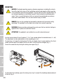
AMBIENT TEMPERATURE
Please observe the maximum ambient temperature in operation specified in the tech-
nical data. A special protection circuit in the headlamp ensures that the brightness
is reduced if the ambient temperature is too high to protect the unit components. If
you notice a significant loss of brightness in the headlamp, please check the ambient
temperature in the direct vicinity of the headlamp and, if necessary, ensure that the
temperature is brought to or below the maximum permitted value.

11
DMX DEUTSCHFRANCAIS
ESPAÑOL ENGLISH
ITALIANO POLSKI
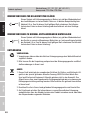
INSTRUCTIONS FOR INDOOR INSTALLATION EQUIPMENT
1. Equipment for installation applications is designed for continuous operation.
2. Equipment for indoor installation is not weather-resistant.
3. Surfaces and plastic parts can also age in installation equipment, e.g. due to UV ir-
radiation and temperature fluctuations. This generally does not impair functionality.
4. With permanently installed devices, the accumulation of impurities, e.g. dust, is to
be expected. Always observe the care instructions.
5. Unless explicitly stated otherwise on the device or in the technical data, the devices
are intended for installation heights of less than 5 m.
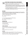
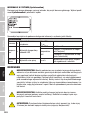
INCLUDED
Remove the product from the packaging and remove all packaging material. Please check the
completeness and integrity of the delivery and notify your distribution partner immediately after
purchase if the delivery is not complete or if it is damaged.
Included in the scope of delivery of the product CLG4FC are:
X1 x Cameo G4FC Spotlight, black
XUser manual
The scope of delivery of the product CLG4FCWH includes:
X1 x Cameo G4FCWH Spotlight, white
XUser manual
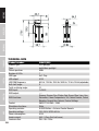
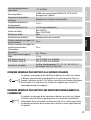
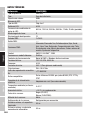
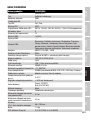
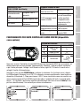
INTRODUCTION
LED Gallery Light with one 40 W RGBL LED
CLG4FC (black housing)
CLG4FCWH (white housing)
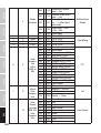
CONTROL FUNCTIONS
1CH, 2CH 16 bit, 3CH CCT, 3CH Presets, 4CH Direct, 5CH HSI,
8CH Direct + CCT and 12CH 16 Bit Full Access DMX Control
W-DMX™
Standalone function (set up via Cameo Unicon)
FEATURES
Compatible with GLOBAL pro (formerly NOKIA) XTS, XTTS and XTSC 3-phase tracks.
40 W RGBL LED. W-DMX™. DMX512. RJ45-Anschluss. Operating voltage: 100–240 V AC.
Diffusing screens, filters and straightening grids optionally available.

12
DMX
ITALIANO
POLSKI
ESPAÑOL
FRANCAIS
DEUTSCHENGLISH
The spotlight features the RDM standard (Remote Device Management). This remote device
management enables the status query and configuration of RDM end devices via an RDM-capable
controller, such as the optionally available Cameo UNICON (item number CLIREMOTE).
The Cameo UNICON also allows access to the entire fixture menu.
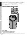
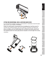
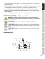
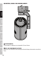
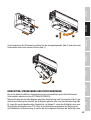
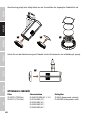
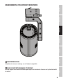
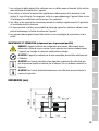
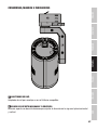
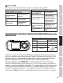
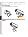
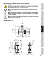
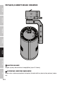
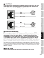
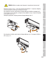
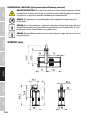
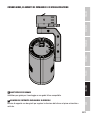
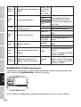
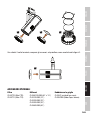
CONNECTIONS, OPERATING AND DISPLAY ELEMENTS
1 RAIL ADAPTER
Rail adapter for mounting on a compatible 3-phase rail.
2 TILTABLE AND SWIVELLING SUPPORT ARM
Support arm with two joints for adjusting the beam direction on the horizontal and vertical plane.
1
2
3
4
5

13
DMX DEUTSCHFRANCAIS
ESPAÑOL ENGLISH
ITALIANO POLSKI
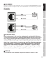
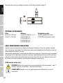
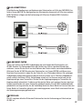
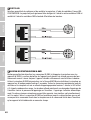
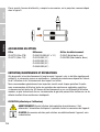
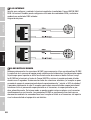
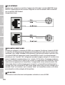
3 RJ45 INTERFACE
Interface for configuring and controlling the fixture using the Cameo UNICON DMX/RDM controller.
The fixture can also be configured using another RDM controller and controlled using a standard
DMX controller.
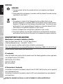
Pin assignment:
4 W-DMX RESET BUTTON
Button for disconnecting W-DMX connections and for pairing the spotlight with W-DMX devices.
The housing surface of the device can become very hot during regular operation. Always allow the
unit to cool down sufficiently before operating the button. Activate the fixture's W-DMX receiver
via Cameo UNICON and reset the receiver by pressing the button for about 3 seconds. All previous
connections are disconnected and the receiver is put into pairing standby for about 1 minute, the
status LED no. 5 flashes red quickly. The receiver is now waiting for a transmitter pairing request.
Start the pairing process on the transmitter; the pairing occurs automatically. In the same way,
several receivers can be paired to a transmitter either simultaneously or one after the other. A
W-DMX connection is always maintained until the connection is disconnected by means of the
Reset command in the receiver or the Unlink command in the transmitter, regardless of whether a
device has been disconnected from the power supply in the meantime.
5 STATUS LED
The LED shows the current status of the spotlight when controlled via cable and W-DMX.

14
DMX
ITALIANO
POLSKI
ESPAÑOL
FRANCAIS
DEUTSCHENGLISH
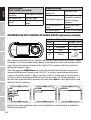
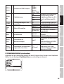
Control via cable
(RJ45, W-DMX deactivated)
LED lights up perma-
nently blue DMX signal is present
LED flashes blue No DMX signal
LED off Stand-alone oper-
ation
Control via W-DMX™
LED flashes red with
approx.1Hz Activate W-DMX
LED flashes red quickly
Pairing with a
transmitter cancelled
and set to pairing
readiness
LED is permanently lit
green
Paired, DMX signal
present
LED flashes green Paired, no DMX signal
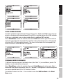
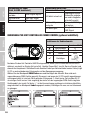
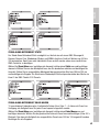
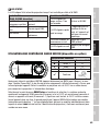
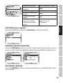
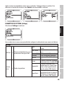
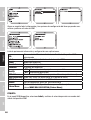
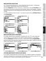
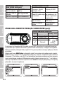
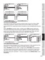
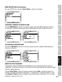
OPERATION PER UNIT CONTROLLER CAMEO UNICON (optionally available)
Functions of the controls
Display Encoder + BACK
Value up ↻
Value down ↺
Back Back
✔Confirm
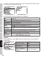
After you have switched on the Unit Controller UNICON (briefly press BACK to switch on), "Update,
Please Wait" (for service purposes only) appears in the display for a short time and then the main
menu. Connect the remote unit to the Gallery Light G4 FC via network cable and connect the
spotlight to the power supply.
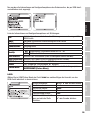
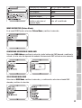
Select the menu item RDM/Fixture and confirm the selection. Now the system searches for
connected RDM devices (Discovery) and if the G4 FC is correctly connected and switched on,
a device is found (Discovered: 1). After a short time, the G4 FC is displayed as the only unit in a
list (the first part of the displayed RDM unit shows the unit model, the second part behind "/" is
the label and can be individually adjusted in the menu item Label for easier identification). Now
confirm to enter the submenu.
All information and configuration options for the spotlight that can be called up and edited via
RDM are now displayed.

15
DMX DEUTSCHFRANCAIS
ESPAÑOL ENGLISH
ITALIANO POLSKI
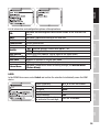
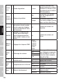
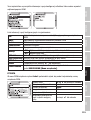
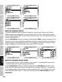
List of information and configuration options with explanations:
UID: Individual and unchangeable identification number of the selected RDM
device
Label: Individually adjustable marking of the RDM unit
Model: Device model
Manufacturer: Device manufacturer
Firmware: Device firmware
Identify: ON Selected spotlight flashes with approx. 1 Hz
OFF Flashing disabled
DMX address Current DMX start address (can be edited in the menu option)
DMX Personality: Current DMX mode (can be edited in the menu option)
DMX slots: Number of channels in current DMX mode
Sensor LED temperature (press ✔ to display)
Fixture Menu Individual Cameo device menu for editing settings (see DEVICE MENU
(Fixture Menu))
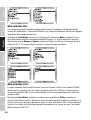
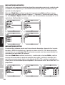
LABEL
In the RDM/Fixture menu, select Label and confirm the selection to individually name the RDM
device.
Select characters: or or turn the encoder
Delete all characters: Reset
Set space: Space
Reset position: Clean
Secure labelling: Save
Confirm command or charac-
ter and select the next digit: Press ✔ or encoder

16
DMX
ITALIANO
POLSKI
ESPAÑOL
FRANCAIS
DEUTSCHENGLISH
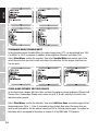
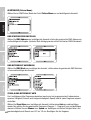
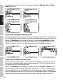
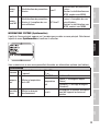
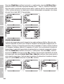
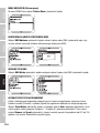
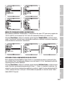
DEVICE MENU (Fixture Menu):
In the RDM/Fixture menu, select Fixture Menu and confirm the selection.
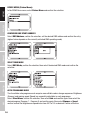
CONFIGURE DMX START ADDRESS
Select DMX Address, confirm the selection, set the desired DMX address and confirm the entry.
(highest value depends on the currently activated DMX operating mode)
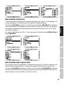
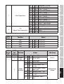
SELECT DMX MODE
Select DMX Mode, confirm the selection, then select the desired DMX mode and confirm the
selection.
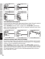
AUTO STANDALONE MODE
The 6 available auto-programs each comprise non-editable colour-change sequences. Brightness
(Dimmer) and running speed (Speed) are separately adjustable in each programme.
Select Stand Alone, confirm the selection, then select Auto and confirm again. Now select the
desired program (Program 1- Program 6) and confirm again. Now select Dimmer or Speed,
confirm and set the brightness or speed value from 001 to 100 as desired. Confirm all entries.

17
DMX DEUTSCHFRANCAIS
ESPAÑOL ENGLISH
ITALIANO POLSKI
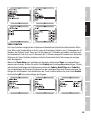
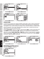
STATIC STANDALONE MODE
The Static standalone mode allows the Dimmer, Dimmer Fine, Strobe and RGBAL values to be set
directly on the device with values between 000 and 255, in a similar way to with a DMX controller.
In this way, an individual scene can be created without an additional DMX controller.
Select Stand Alone, confirm the selection, then select Static and confirm again. Now select the
menu item you wish to edit and confirm the selection. In the selected menu item, set the desired
value from 000 to 255 and confirm the entry. The values for the strobe effect correspond to the
values in channel 2 of the DMX table 3 CH presets.
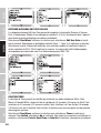
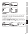
STANDALONE MODE COLOR MACRO
15 different colour macros and 4 individual colours (User Color 1-4) are available as presets. The
brightness can be adjusted for each preset.
Select Stand Alone, confirm the selection, then select Color Macro and confirm again. Select
the desired colour preset and confirm (Color Off = blackout). The brightness of the selected preset
can now be adjusted from 000 to 100. Confirm all entries.
The individual colours User Color 1-4 are created in menu item Edit User Color in the Stand
Alone menu.

18
DMX
ITALIANO
POLSKI
ESPAÑOL
FRANCAIS
DEUTSCHENGLISH
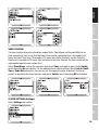
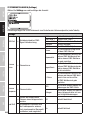
STANDALONE MODE TUNEABLE WHITE
In the standalone mode Tuneable White, the colour temperature (CCT) can be adjusted from 1800
K to 6500 K in 100 K increments, in addition to the brightness (Dimmer) and colour (Tint).
Select Stand Alone, confirm the selection, then select Tunable White and confirm again. Now
select the menu item you wish to edit and confirm the selection. Set the desired value and con-
firm the entry.
STAND-ALONE CATEGORY EDIT USER COLOUR
In the stand-alone category Edit User Color, you have the option of saving brightness (Dimmer and
Dimmer Fine), stroboscope (Strobe) and a colour mix of R, G, B and L directly in the unit in four
individual colour presets.
Select Stand Alone, confirm the selection, then select Edit User Color and confirm again. Select
the desired preset (Color 1- Color 4) and confirm the selection. Now select the menu item you
wish to edit and confirm. Set the desired value from 000 to 255 and confirm again. The values for
the strobe effect correspond to the values in channel 2 of the DMX table 3 CH presets.

19
DMX DEUTSCHFRANCAIS
ESPAÑOL ENGLISH
ITALIANO POLSKI
TIMER FUNCTION
The timer function allows the standalone modes Static, Color Macro and Tuneable White to be
timer controlled in such a way that the Fade In time can be configured from 0.5 seconds to 24
hours, the Dwell Time from 0.5 seconds to 24 hours and infinite (Limitless) and the Fade Out
time from 0.5 seconds to 24 hours. After activation of the timer function, the timer control will be
implemented upon the next system start.
Select Stand Alone, confirm the selection, then select Timer and confirm again. Under Switch,
select the setting On and confirm. For the individual timer control settings, select Fade In, Dwell
Time or Fade Out and confirm. You can now set the respective value as desired. Confirm all
entries. To deactivate the timer function, under point Switch, select the setting Off and confirm.
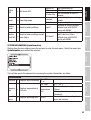
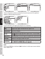
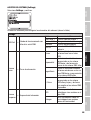
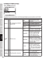
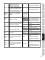
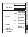
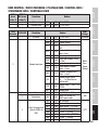
SYSTEM SETTINGS (Settings)
Select Settings and confirm.

20
DMX
ITALIANO
POLSKI
ESPAÑOL
FRANCAIS
DEUTSCHENGLISH
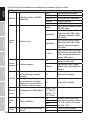
This will take you to the submenu for configuring the submenu items (see table):
Settings
DMX Fail = Operational status with DMX
signal fault
Hold Last command is retained
User Colour 1 Activates User Color 1
Fade out 10s 10 seconds fade to blackout
Blackout Activates blackout
Full On All LEDs 100% output
Dimmer
Curve = Dimmer curve
Linear Light intensity increases linearly
with DMX value
Exponential
Light intensity can be finely
adjusted at lower DMX values
and broadly adjusted at higher
DMX values
Logarithmic
Light intensity can be broadly
adjusted at lower DMX values
and finely adjusted at higher
DMX values
S-curve
Light intensity can be finely ad-
justed at lower and higher DMX
values and broadly adjusted at
medium DMX values
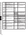
Dimmer
Response = Dimmer response
LED Light responds abruptly to
changes in DMX value
Halogen
Light behaves like a halogen
spotlight with slight brightness
changes
Red Shift
=
Accurately mimics the colour
drift of dimming a halogen
spotlight.
Off Colour drift is disabled
Spotlight, the colour tempera-
ture automatically changes
progressively to warm white
and amber (and vice versa).
On Colour drift is enabled
PWM Fre-
quency =Configuration of PWM frequen-
cy
800 Hz / 1200
Hz / 2000 Hz /
3600 Hz / 12
kHz / 25 kHz
Calibra-
tion = Colour calibration
Red Individual colour calibration.
Cross-mode brightness setting
of R, G, B, A and L with values
from 000 - 255.
Green
Blue
Lime
W-DMX = Switching wireless control on
and off
Off Wireless control disabled
On Wireless control activated
La pagina si sta caricando...
La pagina si sta caricando...
La pagina si sta caricando...
La pagina si sta caricando...
La pagina si sta caricando...
La pagina si sta caricando...
La pagina si sta caricando...
La pagina si sta caricando...
La pagina si sta caricando...
La pagina si sta caricando...
La pagina si sta caricando...
La pagina si sta caricando...
La pagina si sta caricando...
La pagina si sta caricando...
La pagina si sta caricando...
La pagina si sta caricando...
La pagina si sta caricando...
La pagina si sta caricando...
La pagina si sta caricando...
La pagina si sta caricando...
La pagina si sta caricando...
La pagina si sta caricando...
La pagina si sta caricando...
La pagina si sta caricando...
La pagina si sta caricando...
La pagina si sta caricando...
La pagina si sta caricando...
La pagina si sta caricando...
La pagina si sta caricando...
La pagina si sta caricando...
La pagina si sta caricando...
La pagina si sta caricando...
La pagina si sta caricando...
La pagina si sta caricando...
La pagina si sta caricando...
La pagina si sta caricando...
La pagina si sta caricando...
La pagina si sta caricando...
La pagina si sta caricando...
La pagina si sta caricando...
La pagina si sta caricando...
La pagina si sta caricando...
La pagina si sta caricando...
La pagina si sta caricando...
La pagina si sta caricando...
La pagina si sta caricando...
La pagina si sta caricando...
La pagina si sta caricando...
La pagina si sta caricando...
La pagina si sta caricando...
La pagina si sta caricando...
La pagina si sta caricando...
La pagina si sta caricando...
La pagina si sta caricando...
La pagina si sta caricando...
La pagina si sta caricando...
La pagina si sta caricando...
La pagina si sta caricando...
La pagina si sta caricando...
La pagina si sta caricando...
La pagina si sta caricando...
La pagina si sta caricando...
La pagina si sta caricando...
La pagina si sta caricando...
La pagina si sta caricando...
La pagina si sta caricando...
La pagina si sta caricando...
La pagina si sta caricando...
La pagina si sta caricando...
La pagina si sta caricando...
La pagina si sta caricando...
La pagina si sta caricando...
La pagina si sta caricando...
La pagina si sta caricando...
La pagina si sta caricando...
La pagina si sta caricando...
La pagina si sta caricando...
La pagina si sta caricando...
La pagina si sta caricando...
La pagina si sta caricando...
La pagina si sta caricando...
La pagina si sta caricando...
La pagina si sta caricando...
La pagina si sta caricando...
La pagina si sta caricando...
La pagina si sta caricando...
La pagina si sta caricando...
La pagina si sta caricando...
La pagina si sta caricando...
La pagina si sta caricando...
La pagina si sta caricando...
La pagina si sta caricando...
La pagina si sta caricando...
La pagina si sta caricando...
La pagina si sta caricando...
La pagina si sta caricando...
La pagina si sta caricando...
La pagina si sta caricando...
La pagina si sta caricando...
La pagina si sta caricando...
La pagina si sta caricando...
La pagina si sta caricando...
La pagina si sta caricando...
La pagina si sta caricando...
La pagina si sta caricando...
La pagina si sta caricando...
La pagina si sta caricando...
La pagina si sta caricando...
La pagina si sta caricando...
La pagina si sta caricando...
La pagina si sta caricando...
La pagina si sta caricando...
La pagina si sta caricando...
La pagina si sta caricando...
La pagina si sta caricando...
La pagina si sta caricando...
La pagina si sta caricando...
La pagina si sta caricando...
La pagina si sta caricando...
La pagina si sta caricando...
La pagina si sta caricando...
La pagina si sta caricando...
La pagina si sta caricando...
La pagina si sta caricando...
La pagina si sta caricando...
La pagina si sta caricando...
La pagina si sta caricando...
La pagina si sta caricando...
La pagina si sta caricando...
La pagina si sta caricando...
La pagina si sta caricando...
La pagina si sta caricando...
La pagina si sta caricando...
La pagina si sta caricando...
La pagina si sta caricando...
La pagina si sta caricando...
La pagina si sta caricando...
La pagina si sta caricando...
La pagina si sta caricando...
La pagina si sta caricando...
La pagina si sta caricando...
La pagina si sta caricando...
La pagina si sta caricando...
La pagina si sta caricando...
-
 1
1
-
 2
2
-
 3
3
-
 4
4
-
 5
5
-
 6
6
-
 7
7
-
 8
8
-
 9
9
-
 10
10
-
 11
11
-
 12
12
-
 13
13
-
 14
14
-
 15
15
-
 16
16
-
 17
17
-
 18
18
-
 19
19
-
 20
20
-
 21
21
-
 22
22
-
 23
23
-
 24
24
-
 25
25
-
 26
26
-
 27
27
-
 28
28
-
 29
29
-
 30
30
-
 31
31
-
 32
32
-
 33
33
-
 34
34
-
 35
35
-
 36
36
-
 37
37
-
 38
38
-
 39
39
-
 40
40
-
 41
41
-
 42
42
-
 43
43
-
 44
44
-
 45
45
-
 46
46
-
 47
47
-
 48
48
-
 49
49
-
 50
50
-
 51
51
-
 52
52
-
 53
53
-
 54
54
-
 55
55
-
 56
56
-
 57
57
-
 58
58
-
 59
59
-
 60
60
-
 61
61
-
 62
62
-
 63
63
-
 64
64
-
 65
65
-
 66
66
-
 67
67
-
 68
68
-
 69
69
-
 70
70
-
 71
71
-
 72
72
-
 73
73
-
 74
74
-
 75
75
-
 76
76
-
 77
77
-
 78
78
-
 79
79
-
 80
80
-
 81
81
-
 82
82
-
 83
83
-
 84
84
-
 85
85
-
 86
86
-
 87
87
-
 88
88
-
 89
89
-
 90
90
-
 91
91
-
 92
92
-
 93
93
-
 94
94
-
 95
95
-
 96
96
-
 97
97
-
 98
98
-
 99
99
-
 100
100
-
 101
101
-
 102
102
-
 103
103
-
 104
104
-
 105
105
-
 106
106
-
 107
107
-
 108
108
-
 109
109
-
 110
110
-
 111
111
-
 112
112
-
 113
113
-
 114
114
-
 115
115
-
 116
116
-
 117
117
-
 118
118
-
 119
119
-
 120
120
-
 121
121
-
 122
122
-
 123
123
-
 124
124
-
 125
125
-
 126
126
-
 127
127
-
 128
128
-
 129
129
-
 130
130
-
 131
131
-
 132
132
-
 133
133
-
 134
134
-
 135
135
-
 136
136
-
 137
137
-
 138
138
-
 139
139
-
 140
140
-
 141
141
-
 142
142
-
 143
143
-
 144
144
-
 145
145
-
 146
146
-
 147
147
-
 148
148
-
 149
149
-
 150
150
-
 151
151
-
 152
152
-
 153
153
-
 154
154
-
 155
155
-
 156
156
-
 157
157
-
 158
158
-
 159
159
-
 160
160
-
 161
161
-
 162
162
-
 163
163
-
 164
164


in altre lingue
- français: Cameo G4 FC Manuel utilisateur
- español: Cameo G4 FC Manual de usuario
- Deutsch: Cameo G4 FC Benutzerhandbuch
- polski: Cameo G4 FC Instrukcja obsługi
Documenti correlati
-
Cameo G4 T Manuale utente
-
-
-
-
-
-
-
-
Cameo F2 FC IP Manuale utente
-


