Cameo OPUS® SP5+ Manuale utente
- Categoria
- Proiettori
- Tipo
- Manuale utente

USER´S MANUAL
BEDIENUNGSANLEITUNG
MANUEL D`UTILISATION
MANUAL DE USUARIO
INSTRUKCJA OBSŁUGI
MANUALE D‘ USO
OPUS SP5 PLUS
PROFILE MOVING HEAD
CLOSP5PLUS

CONTENTS / INHALTSVERZEICHNIS / CONTENU /
CONTENIDO / TREŚĆ / CONTENUTO
ENGLISH
INFORMATION ON THIS USER MANUAL 4
INTENDED USE 4
DEFINITIONS AND SYMBOL EXPLANATIONS 4
SAFETY INSTRUCTIONS 5
NOTES FOR MOBILE INDOOR DEVICES 8
INCLUDED 9
INTRODUCTION 9
CONNECTIONS, OPERATING AND DISPLAY ELEMENTS 10
OPERATION 13
SETUP AND INSTALLATION 20
CARE, MAINTENANCE AND REPAIR 21
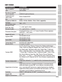
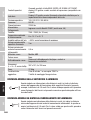
TECHNICAL DATA 22
MINIMUM DISTANCE TO ILLUMINATED SURFACE 23
MINIMUM DISTANCE TO NORMALLY FLAMMABLE MATERIALS 23
DISPOSAL 24
MANUFACTURER’S DECLARATIONS 24
DEUTSCH
INFORMATIONEN ZU DIESER BEDIENUNGSANLEITUNG 25
BESTIMMUNGSGEMÄSSER GEBRAUCH 25
BEGRIFFS- UND SYMBOLERKLÄRUNGEN 25
SICHERHEITSHINWEISE 26
HINWEISE FÜR ORTSVERÄNDERLICHE INDOOR-GERÄTE 30
LIEFERUMFANG 30
EINFÜHRUNG 30
ANSCHLÜSSE, BEDIEN- UND ANZEIGEELEMENTE 31
BEDIENUNG 34
AUFSTELLUNG UND MONTAGE 42
PFLEGE, WARTUNG UND REPARATUR 43
TECHNISCHE DATEN 44
MINDESTABSTAND ZUR BELEUCHTETEN FLÄCHE 46
MINDESTABSTAND ZU NORMAL ENTFLAMMBAREN MATERIALIEN 46
ENTSORGUNG 46
HERSTELLERERKLÄRUNGEN 46

FRANÇAIS
INFORMATIONS SUR CE MANUEL D'UTILISATION 48
UTILISATION PRÉVUE 48
DÉFINITIONS ET EXPLICATION DES PICTOGRAMMES 48
CONSIGNES DE SÉCURITÉ 49
NOTES POUR LES APPAREILS MOBILES D'INTÉRIEUR 53
LIVRAISON INCLUSE 53
INTRODUCTION 54
CONNECTEURS, UTILISATION ET INDICATEURS 55
FONCTIONNEMENT 58
MONTAGE ET INSTALLATION 66
ENTRETIEN, MAINTENANCE ET RÉPARATIONS 67
CARACTÉRISTIQUES TECHNIQUES 68
DISTANCE MINIMALE PAR RAPPORT À LA SURFACE ÉCLAIRÉE 70
DISTANCE MINIMALE PAR RAPPORT AUX MATÉRIAUX NORMALEMENT INFLAMMABLES 70
MISE AU REBUT 70
DÉCLARATIONS DU FABRICANT 71
ESPAÑOL
INFORMACIÓN SOBRE ESTE MANUAL DEL USUARIO 72
USO PREVISTO 72
DEFINICIONES Y EXPLICACIONES DE LOS SÍMBOLOS 72
INSTRUCCIONES DE SEGURIDAD 73
NOTAS PARA LOS EQUIPOS PORTÁTILES QUE SE INSTALAN EN INTERIORES 77
ENTREGA INCLUIDA 77
INTRODUCCIÓN 77
CONEXIONES, MANDOS E INDICADORES 78
FUNCIONAMIENTO 81
INSTALACIÓN Y MONTAJE 89
CUIDADO, MANTENIMIENTO Y REPARACIÓN 90
DATOS TÉCNICOS 91
DISTANCIA MÍNIMA A LA SUPERFICIE ILUMINADA 93
DISTANCIA MÍNIMA A MATERIALES NORMALMENTE INFLAMABLES 93
RECICLAJE 93
DECLARACIÓN DEL FABRICANTE 94

POLSKI
INFORMACJE NA TEMAT NINIEJSZEJ INSTRUKCJI OBSŁUGI 95
ZAMIERZONE ZASTOSOWANIE 95
DEFINICJE I OBJAŚNIENIA SYMBOLI 95
INSTRUKCJE BEZPIECZEŃSTWA 96
UWAGI DOTYCZĄCE MOBILNYCH URZĄDZEŃ WEWNĘTRZNYCH 100
DOSTAWA WLICZONA W CENĘ 100
WPROWADZENIE 101
PRZYŁĄCZA, ELEMENTY OBSŁUGI I WSKAŹNIKI 102
OBSŁUGA 105
KONFIGURACJA I INSTALACJA 113
PIELĘGNACJA, KONSERWACJA I NAPRAWA 113
DANE TECHNICZNE 114
MINIMALNA ODLEGŁOŚĆ OD OŚWIETLANEJ POWIERZCHNI 116
MINIMALNA ODLEGŁOŚĆ OD NORMALNIE ŁATWOPALNYCH MATERIAŁÓW 116
UTYLIZACJA 116
DEKLARACJE PRODUCENTA 117
ITALIANO
INFORMAZIONI SU QUESTO MANUALE DI ISTRUZIONI 118
USO PREVISTO 118
DEFINIZIONI E SPIEGAZIONI DEI SIMBOLI 118
ISTRUZIONI DI SICUREZZA 119
NOTE PER I DISPOSITIVI MOBILI PER INTERNI 123
CONSEGNA INCLUSA 123
INTRODUZIONE 123
CONNESSIONI, ELEMENTI DI COMANDO E DI VISUALIZZAZIONE 124
FUNZIONAMENTO 127
INSTALLAZIONE E MONTAGGIO 135
CURA, MANUTENZIONE E RIPARAZIONE 136
DATI TECNICI 137
DISTANZA MINIMA DALLA SUPERFICIE ILLUMINATA 138
DISTANZA MINIMA DA MATERIALI NORMALMENTE INFLAMMABILI 138
SMALTIMENTO 139
DICHIARAZIONI DEL PRODUTTORE 139


6
DMX
ITALIANO
POLSKI
ESPAÑOL
FRANCAIS
DEUTSCHENGLISH
ENGLISH
You have made the right choice!
This device has been developed and manufactured to the highest quality standards to ensure
many years of problem-free operation. Please read this user manual carefully to be able to use
your new Cameo product quickly and optimally. Further information about Cameo Light is availab-
le on our website CAMEOLIGHT.COM.
INFORMATION ON THIS USER MANUAL
• Carefully read the safety instructions and the entire manual before operating the device.
• Observe the warnings on the device and in the user manual.
• Always keep the user manual within reach.
• If you sell or pass on the device, it is important that you also include this user manual, as it is
an integral part of the product.
INTENDED USE
The product is a device for event technology!
This product has been developed for professional use in the field of event technology and is not
suitable for use as domestic lighting!
Furthermore, this product is only intended for qualified users with specialist knowledge of event
technology!
Use of the product outside the specified technical data and operating conditions is considered
inappropriate!
Liability for damage and third-party damage to persons and property due to inappropriate use is
excluded!
The product is not suitable for:
• Use by persons (including children) with limited physical, sensory or mental abilities or lack of
experience and knowledge.
• Children (children must be instructed not to play with the device).
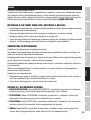
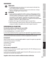
DEFINITIONS AND SYMBOL EXPLANATIONS
1. DANGER: The word DANGER, possibly in combination with a symbol, indicates immediately
dangerous situations or conditions for life and limb.
2. WARNING: The word WARNING, possibly in combination with a symbol, indicates potentially
dangerous situations or conditions for life and limb.
3. CAUTION: The word CAUTION, possibly in combination with a symbol, is used to indicate situa-
tions or conditions that may lead to injury.
4. ATTENTION: The word ATTENTION, possibly in combination with a symbol, refers to situations
or states that can lead to damage to property and/or the environment.

7
DMX DEUTSCHFRANCAIS
ESPAÑOL ENGLISH
ITALIANO POLSKI
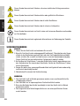
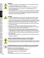
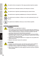
This symbol identifies hazards that can cause electric shock.
This symbol identifies hazardous areas or hazardous situations.
This symbol indicates hazards caused by hot surfaces.
This symbol indicates hazards caused by intense light sources.
This symbol indicates a device in which there are no user-replaceable parts.
This symbol indicates additional information on the operation of the product.
SAFETY INSTRUCTIONS
HAZARD:
1. Do not open or modify the unit.
2. If your device no longer functions properly, if liquids or objects get inside it or if it
has been damaged in any other way, switch it off immediately and disconnect it
from the mains. The device may be repaired only by authorised repair technicians.
3. For devices of protection class 1, the protective conductor must be connected
correctly. Never disconnect the protective conductor. Devices of protection class 2
do not have a protective conductor.
4. Ensure that live cables are not kinked or otherwise mechanically damaged.
5. Never bypass the unit fuse.
WARNING:
1. The device may not be operated if it shows obvious signs of damage.
2. The device may only be installed in a voltage-free state.
3. If the mains cable of the device is damaged, do not operate the device.
4. Permanently connected power cables may only be replaced by a qualified person.
ATTENTION:
1. Do not operate the unit if it has been exposed to large temperature fluctuations
(for example, after transport). Moisture and condensation can damage the device.
Switch on the device only when it has reached room temperature.
2. Make sure that the voltage and frequency of the mains supply correspond to the
values indicated on the unit. If the device has a voltage selector switch, do not
connect the device until it has been set correctly. Use only suitable power cables.

8
DMX
ITALIANO
POLSKI
ESPAÑOL
FRANCAIS
DEUTSCHENGLISH
3. To disconnect the unit from the mains at all poles, it is not sufficient to press the
on/off switch on the unit.
4. Make sure that the fuse used corresponds to the type printed on the unit.
5. Make sure that appropriate measures have been taken against overvoltage (e.g.
lightning strike).
6. Observe the specified maximum output current on units with Power Out connec-
tion. Ensure that the total current consumption of all connected devices does not
exceed the specified value.
7. Replace pluggable mains cables only with original cables.
HAZARD:
1. Danger of suffocation! Plastic bags and small parts must be kept out of reach of
persons (including children) with reduced physical, sensory or mental capabilities.
2. Danger from falling down! Make sure that the device is securely installed and will
not fall down. Only use suitable stands or mounts (particularly for fixed installa-
tions). Ensure that accessories are properly installed and secured. Ensure that
applicable safety regulations are observed.
WARNING:
1. Use the device only in the manner intended.
2. Operate the device only with the accessories recommended and intended by the
manufacturer.
3. During installation, observe the safety regulations applicable in your country.
4. After connecting the unit, check all cable routes to avoid damage or accidents, e.g.
due to tripping hazards.
5. Always observe the specified minimum distance to normally flammable materials!
Unless explicitly stated, the minimum distance is 0.3 m.
6. Always observe the minimum distance to the illuminated surface that can be read
on the device!
CAUTION:
1. In the case of moving components such as mounting brackets or other moving
components, there is a possibility of jamming.
2. In the case of units with motor-driven components, there is a risk of injury from the
movement of the unit. Sudden movement of the device can cause shock reactions.
3. The housing surface of the device can become very hot during regular operation.
Ensure that accidental touching of the housing is not possible. Always allow the
lamp to cool sufficiently before removal, maintenance work and charging etc.

9
DMX DEUTSCHFRANCAIS
ESPAÑOL ENGLISH
ITALIANO POLSKI
ATTENTION:
1. Do not install or use the device in the vicinity of radiators, accumulators, stoves, or
other heat sources. Ensure that the device is always installed in such a way that it is
sufficiently cooled and cannot overheat.
2. Do not place any ignition sources, such as burning candles, near the device.
3. Ventilation openings must not be covered and fans must not be blocked.
4. Use the original packaging or packaging provided by the manufacturer for trans-
port.
5. Avoid shock or impact to the unit.
6. Observe the IP protection class as well as the ambient conditions such as tempera-
ture and humidity according to the specification.
7 Devices can be continuously further developed. In the event of deviating information on
operating conditions, performance or other device properties between the user manual
and the device labelling, the information on the device always takes priority.
8. The unit is not suitable for tropical climates and for operation above 2000 m above
sea level.
9. Unless explicitly stated, the unit is not suitable for operation in marine conditions .
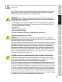
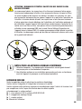
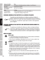
CAUTION! IMPORTANT INFORMATION REGARDING LIGHTING PRODUCTS!
1. Never look directly into the beam of light, not even for a short period of time.
2. Never look into the beam of light using optical devices such as a magnifying glass.
3. Stroboscopic effects may cause epileptic seizures in susceptible individuals!
SIGNAL TRANSMISSION BY RADIO (E.G. W-DMX OR AUDIO RADIO SYSTEMS):
The quality and performance of wireless signal transmissions generally depends on
the ambient conditions.
The following factors can impact range and signal stability, for example:
Shielding (e.g. masonry, metal structures, water)
High volume of radio traffic (e.g. powerful wireless LAN networks)
Interference
Electromagnetic radiation (e.g. LED video screens, dimmers)
All range specifications refer to free-field application with visual contact and without
interference!
The operation of transmission systems is subject to official regulations. These may
vary from region to region and must be checked by the operator before use (e.g. radio
frequency and transmission power).

10
DMX
ITALIANO
POLSKI
ESPAÑOL
FRANCAIS
DEUTSCHENGLISH
WARNING: Devices with wireless signal transmission are not suitable for use in sen-
sitive areas in which radio operation can lead to potential detrimental effects. These
include:
• Hospitals, health centres or other healthcare facilities that provide patient treatment
with skilled personnel and equipment.
• Hazardous areas Class I, II and III
• Restricted areas
• Military facilities
• Aircraft or vehicles
• Areas where the use of mobile phones is prohibited
TRANSMISSION VIA W-DMX
WARNING: Ingeneral, wireless DMX transmission must not be used for applications
with safety-related factors that could result in personal injury or property damage in
the event of failure.
This applies in particular to moving scene or traverse structures, DMX-controlled mo-
tors/lifts or lifting devices for operating DMX-operated platform lifts, hydraulic systems
or comparable moving components.
Furthermore, wireless DMX transmission must not be used to trigger flame or py-
rotechnic devices, explosion-driven effects, or to control gas or liquid effects. These
include CO2 cannons, confetti shooters, water effects or similar.
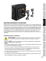
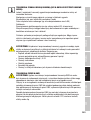
CAUTION! POTENTIAL DAMAGE FROM EXTERNAL LIGHT SOURCES!
Solar radiation, laser radiation and bundled light beams from other spotlights can da-
mage the housing and internal components such as filters, gobo and colour wheels,
motors, cables, belts, etc., as well as light sources!
Do not expose the unit and especially the lens opening to direct sunlight, laser radi-
ation and bundled light beams from other spotlights during unpacking, installation,
prolonged non-use and operation! Always point the lens opening towards the floor
when the unit is not in use! For this purpose, also use the Sun Protection function,
which can be activated via DMX command (see Device Settings channel in the DMX
table). An integrated gyroscope sensor detects the position of use. Damage caused by
external light sources is excluded from the manufacturer's warranty!

11
DMX DEUTSCHFRANCAIS
ESPAÑOL ENGLISH
ITALIANO POLSKI
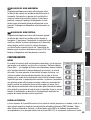
NOTES FOR MOBILE INDOOR DEVICES
1. Temporary operation! Event equipment is generally only designed for temporary
operation.
2. Continuous operation or permanent installation can impair the functioning of the
device and cause premature ageing.
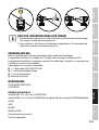
INCLUDED
Remove the product from the packaging and remove all packaging material.
Please check the completeness and integrity of the delivery and notify
Please contact your sales partner immediately after the purchase if the delivery is not complete or
is damaged. The packaging includes:
X1 x OPUS SP5 PLUS LED Moving Head
X2 x Omega mounting bracket
X1x Power cord
XUser manual
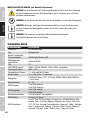
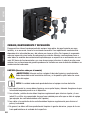
INTRODUCTION
MOVING HEAD OPUS SERIES
CLOSP5PLUS
CONTROL FUNCTIONS:
34-channel and 50-channel DMX control (CLOSP5PLUS)
27-channel and 33-channel DMX control (CLOSP5PLUS with optional CLOSP5AM animation
wheel module)
Art-Net
sACN
W-DMX™
RDM-enabled
Master/slave operation
Standalone functions
FEATURES:
500 W High Efficiency LED. Framing Shutter Module. CMY + CTO colour blending Colour wheel
with 7 brilliant colours + open and split colours. Gobo wheel 1 with 8 fixed gobos + open. Gobo
wheel 2 with 7 rotating gobos + open (gobos interchangeable). 2 rotating prisms. Focusing and
zoom function via DMX. Frosted filter and iris Strobe. Pan and tilt motors with 16-bit resolution.
Battery-powered. Display for mains-independent setting. Automatic position correction. Tempera-
ture-controlled fans. 3- and 5-pole DMX connections. RJ45 network connections. Wireless DMX™
Neutrik powerCON TRUE1 mains connections IN and OUT. 2 Omega mounting brackets included.
Operating voltage 100-240 V AC. Power consumption 800W. The spotlight features the RDM
standard (Remote Device Management). Remote device management allows the user to view the
status and configuration of RDM terminals via an RDM-capable controller.

12
DMX
ITALIANO
POLSKI
ESPAÑOL
FRANCAIS
DEUTSCHENGLISH
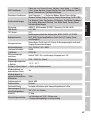
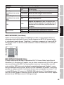
ADDITIONAL PROPERTIES
The CLOSP5P moving head comes equipped with a 4-way framing shutter module. The 4-way
framing shutter module can be interchanged with the CLOSP5AM animation wheel module. The
software and corresponding DMX modes are upgraded automatically.
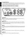
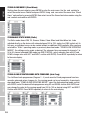
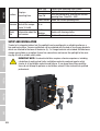
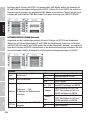
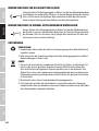
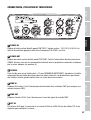
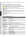
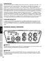
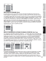
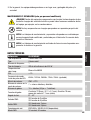
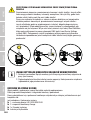
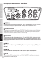
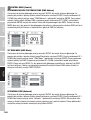
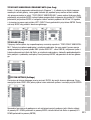
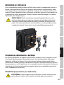
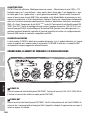
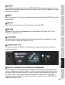
CONNECTIONS, OPERATING AND DISPLAY ELEMENTS
1 23
4 5
6
7
8
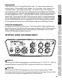
1 POWER IN
Neutrik powerCON TRUE1 mains input socket. Operating voltage 100–240 V AC/50–60 Hz. A
suitable mains cable with powerCON TRUE1 plug is included.
2 POWER OUT
Neutrik powerCON TRUE1 mains output socket. Facilitates power supply to other CAMEO spot-
lights. Ensure that the total power consumption of all devices connected to the device does not
exceed the given ampere (A) value.
3 FUSE
Fuse holder for 5 x 20 mm micro fuses. IMPORTANT NOTE: Replace the fuse only with one of the
same type and rating. In the event of repeated fuse failure, please contact an authorised service
centre.
4 DMX IN
Male 3-pin and 5-pin XLR sockets for connection of a DMX control device (e.g. DMX console).
5 DMX OUT
Female 3-pin or 5-pin XLR sockets for sending the DMX control signal.

13
DMX DEUTSCHFRANCAIS
ESPAÑOL ENGLISH
ITALIANO POLSKI
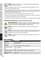
6 NET IN
RJ45 network connector for connecting to an Art-Net or sACN network. Use CAT 5e or better
cables to set up the network.
7 NET OUT
RJ45 network connector for connecting additional Art-Net or sACN-capable devices to the net-
work. Use CAT 5e or better cables to set up the network.
8 ANTENNA FOR W-DMX™
The antenna for control via W-DMX™ remains in the holder (= operating position) during operation.
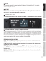
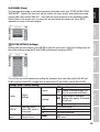
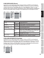
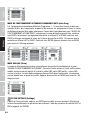
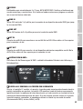
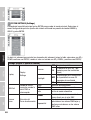
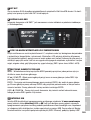
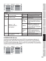
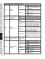
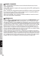
9 PRESSURE SENSITIVE LC DISPLAY WITH ILLUMINATION
Thanks to the pressure-sensitive LC display, the device can be operated directly from the display
(glove-compatible). The LCD display shows the currently activated mode (main display), the menu
items in the selection menu and the numerical value or operating status in certain menu items. If
there is no control signal to the device, the display starts flashing; the flashing stops as soon as a
control signal is present (DMX and slave operation, ArtNet and sACN).
10 TOUCH-SENSITIVE CONTROLS
MODE - Pressing MODE (repeatedly) takes you one level up in the menu structure, to the main
display.
UP and DOWN - Select the individual menu items in the main menu (DMX address, opera-
ting mode, etc.) and in the submenus.
ENTER – Starting from the main display, press ENTER to enter the main menu. In the main menu,
press ENTER to access the menu level in which values can be changed. Confirm value changes by
pressing ENTER.
LEFT and RIGHT X - Use the control panels to change the value of a menu item, such as the
DMX address, as desired.
9
10
11

14
DMX
ITALIANO
POLSKI
ESPAÑOL
FRANCAIS
DEUTSCHENGLISH
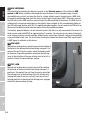
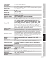
11 USB INTERFACE
USB interface for updating the device firmware. In the Service menu, set the status for USB
update to ON. When available, download the latest firmware from the product page at www.
cameolight.com, unzip it and copy the files to a folder without special characters on a USB stick.
Disconnect the Moving Head from the mains and all input connections (DMX / Ethernet), connect
the USB stick to the USB interface and reconnect the Moving Head to the mains. The USB stick is
automatically recognised and shown in the display. Now navigate to the corresponding folder on
the USB stick and confirm with ON. The update procedure begins. Do not remove the USB stick or
disconnect the Moving Head from the mains during the update procedure.
The battery-powered display can be activated, even if the device is not connected to the mains. To
do this, press and hold MODE for approximately 3 seconds. You can now access device informati-
on to change and save system settings without mains connection. External control of the spotlight
is not activated in this case. For this reason, the display shows that there is no DMX signal even if
a DMX signal is available at the device.
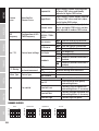
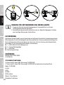
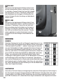
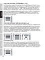
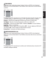
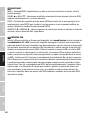
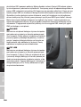
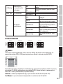
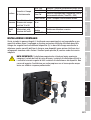
12 PAN LOCK
Mechanical locking device used to prevent the rotation of
the head in the horizontal direction during transport. Dis-
connect the unit from the mains, move the head parallel
to the base (4 possible positions) and push the locking
lever in the direction of the pan rotation axis to lock it in
position. Unlock the device before startup.
13 TILT LOCK
Mechanical locking device used to prevent the rotation
of the head in the vertical direction during transport (7
positions). Disconnect the unit from the mains and slide
the locking lever in the direction of the tilt rotation axis,
moving the head of the unit vertically until one of the 7
locking positions is found and the locking lever engages.
Unlock the device before startup.
13
12

15
DMX DEUTSCHFRANCAIS
ESPAÑOL ENGLISH
ITALIANO POLSKI
OPERATION
NOTES
As soon as the fixture is correctly connected to the mains, "Software
Update Please Wait..." and the Cameo logo with information on the
fixture model are shown in the display one after the other during the
start-up process and the motor reset. After this process, the spotlight is
ready for operation and the previously selected mode will be activa-
ted. On the one hand, the headlamp is operated with the help of the
touch-sensitive control panels next to the display; on the other hand,
the pressure-sensitive display (glove-compatible) itself can be used to
reach all menu items and make settings intuitively as desired. Informa-
tion on which control element in the display and which control panel
next to the display have the same function can be found in the adjacent
table. The following describes the operation using the control panels
next to the display.
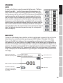
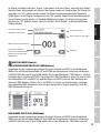
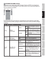
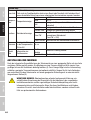
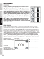
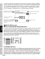
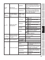
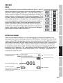
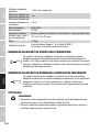
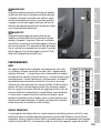
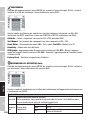
MAIN DISPLAY
The top line of the display shows whether and which control signal is present at the unit, the line
below shows the currently activated operating mode (DMX Standard / Extended, Static, Auto,
Slave) and the DMX start address or the corresponding operating mode (in the example DMX
start address 001) is clearly visible in the middle. As soon as the control signal is interrupted, the
characters in the display start flashing and "None" (no signal) is displayed behind "Signal" in the
upper line. The display can be rotated 180° by tapping the touch-sensitive control panel DOWN; if
the display is already rotated 180°, tap the control panel UP to return the display to the standard
image. The display can also be rotated 180° by pressing the "roof symbol" in the pressure-sensi-
tive display.
Display of the input signal
DMX mode or operating mode
DMX start address or operating mode
Information on the device
model Back to main display =
any position in the display or
Press ENTER
Display battery status
Rotate display by 180
Main menu

16
DMX
ITALIANO
POLSKI
ESPAÑOL
FRANCAIS
DEUTSCHENGLISH
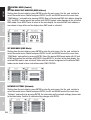
CONTROL MENU (Control)
SETTING DMX START ADDRESS (DMX Address)
Starting from the main display, press ENTER to enter the main menu. Use the and controls to
select the control menu Control and press ENTER. Use UP and DOWN to select the menu item
"DMX Address" and confirm by pressing ENTER. Now set the desired DMX start address using the
LEFT and RIGHT control panels and confirm with ENTER (highest value depends on the activated
DMX mode). Press MODE twice to return to the main display, the selected DMX start address is
now shown in large letters on the display when DMX mode is activated.
SET DMX MODE (DMX Mode)
Starting from the main display, press ENTER to enter the main menu. Use the and controls to
select the control menu Control and press ENTER. Use UP and DOWN to select the menu item
"DMX Mode" and confirm by pressing ENTER. Select the desired DMX mode again with UP and
DOWN and confirm the selection with ENTER. Press MODE 2x to return to the main display, the
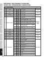
selected DMX mode is now activated. Tables with the channel assignment of the different DMX
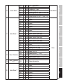
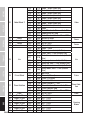
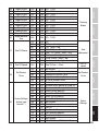
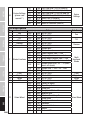
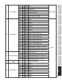
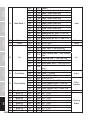
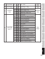
modes can be found in these instructions under DMX CONTROL.
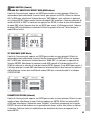
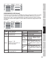
NETWORK SETTINGS (Network)
Starting from the main display, press ENTER to enter the main menu. Use the and controls to
select the control menu Control and press ENTER. Use UP and DOWN to select the menu item
"Network" and confirm by pressing ENTER. For information on the network settings, please refer
to the table below. Confirm all network setting changes with ENTER.

17
DMX DEUTSCHFRANCAIS
ESPAÑOL ENGLISH
ITALIANO POLSKI
Network
Network
Input
Activate / deactivate
network input
OFF Network input deactivated
ON Network input activated
Protocol Network protocol ArtNET ArtNet Protocol
sACN sACN protocol
Address Universe 1 - 256,
Set IP address and subnet mask
Universe
000 - 255
000 to 255. Change value with
LEFT and RIGHT, confirm with
ENTER.
IP Address
Select block with LEFT and RIGHT,
change value with UP and DOWN,
confirm with ENTER.
IP Subnet
Mask
Select block with LEFT and RIGHT,
change value with UP and DOWN,
confirm with ENTER.
DMX OUT Output network signal
via DMX OUT
OFF Do not output signal
ON Output signal
W-DMX SETTINGS (Wireless)
Starting from the main display, press ENTER to enter the main menu. Use the and controls to
select the control menu Control and press ENTER. Use UP and DOWN to select the menu item
"Wireless" and confirm by pressing ENTER. For information on the W-DMX settings, please refer
to the table below. Confirm all changes to the settings with ENTER.
Wireless
W-DMX OFF Deactivate W-DMX
ON Activate W-DMX
Operating
(currently in beta status)
Receiver W-DMX module configured as receiver
Transmitter W-DMX module configured as transmitter
Transmitting
(currently in beta status)
G3 G3 transmission standard
G4s G4S transmission standard
Link Link
Pair with W-DMX devices. W-DMX must be enabled
on all devices, and the pairing with a transmitter
must be reset (Receive Reset)
Unlink Unpair all devices
Receive Reset NO Do not reset transmitter pairing
YES Reset transmitter pairing

18
DMX
ITALIANO
POLSKI
ESPAÑOL
FRANCAIS
DEUTSCHENGLISH
STAND ALONE MODES (Stand Alone)
Starting from the main display, press ENTER to enter the main menu. Use the and controls to
select the control menu Control and press ENTER. Using and , now select the menu item “Stand
Alone” and confirm by pressing ENTER. Now select one of the three stand-alone modes using the
and controls and confirm with ENTER.
STANDALONE STATIC MODE (Static)
The Static mode allows PAN, Tilt, Dimmer, Strobe, Colour Wheel and Gobo Wheel etc. to be
adjusted directly on the device with values between 000 to 255, similar to a DMX control unit. In
this way, an individual scene can be created without an additional DMX controller. After you have
selected the "Static" operating mode, as previously described under "STAND ALONE OPERATING
MODES", the settings can be made as desired. The submenu items correspond to channels 1 to
50 in 50-channel extended DMX mode (see DMX CONTROL, select submenu item with UP and
DOWN, change value with LEFT and RIGHT, confirm with ENTER). Press MODE repeatedly to return
to the main display.
STAND ALONE OPERATION MODE AUTO PROGRAMS (Auto Prog)
The 4 different auto programmes (Program 1 - 4) each consist of fixed programmed head mo-
vements, gobo and colour changes etc., the running speed can be set separately. As previously
described under "STAND ALONE OPERATING MODES", select the Auto operating mode, confirm
with ENTER, select the desired Auto programme using UP and DOWN, confirm with ENTER and
now change the value for the running speed from 000 to 100 as desired using LEFT and RIGHT.
Confirm with ENTER. Press MODE repeatedly to return to the main display.

19
DMX DEUTSCHFRANCAIS
ESPAÑOL ENGLISH
ITALIANO POLSKI
SLAVE MODE (Slave)
The slave operating mode is selected as previously described under item "STAND ALONE OPERA-
TING MODES". Connect the slave unit and the master unit (same model, same software version)
using a DMX cable (master DMX OUT - slave DMX IN) and activate one of the standalone modes
Auto or Static in the master unit. The slave unit will now follow the master unit. Press MODE
repeatedly to return to the main display.
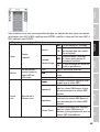
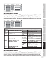
SYSTEM SETTINGS (Settings)
Starting from the main display, press ENTER to enter the main menu. Select the Settings menu for
the system settings using the UP and DOWN control panels and press ENTER.
This will take you to the submenu for setting the submenu items (see table, select with UP and
DOWN, confirm with ENTER, change value or status with UP and DOWN, confirm with ENTER).
Settings (bold = factory setting)
Display Display
Settings
Reverse
OFF No display rotation
ON Display is rotated through 180°
(e.g. for overhead installation)
Backlight OFF
Deactivation of the display
lighting after approx. 30 seconds
of inactivity
ON Display lighting permanently on
DMX fail
Operating status
when DMX signal is
interrupted
Black Activates blackout
Hold Last command is retained
Car activates Auto mode
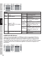
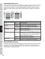
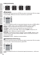
Dimmer
curve
Selecting the
Dimmer curve Linear Light intensity increases linearly with
DMX value

20
DMX
ITALIANO
POLSKI
ESPAÑOL
FRANCAIS
DEUTSCHENGLISH
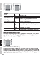
Dimmer
Curve
Selecting the
Dimmer curve
Exponential
Light intensity can be finely adjusted
at lower DMX values and broadly
adjusted at higher DMX values
Logarithmic
Light intensity can be broadly adjusted
at lower DMX values and finely adjus-
ted at higher DMX values
Dimmer curve
Light intensity can be finely adjusted at
lower and higher DMX values and bro-
adly adjusted at medium DMX values
LED
Frequency
Configuration of LED
PWM frequency
650Hz, 1530Hz,
3600Hz, 12KHz,
25KHz
Pan / Tilt Device head settings
Pan reverse OFF Does not reverse pan direction
ON Reverses pan direction
Tilt Reverse OFF Does not reverse tilt direction
ON Reverses tilt direction
Pan Angle 630 Pan angle 630°
540 Pan angle 540°
Feedback
OFF Automatic position correction is
disabled
ON Automatic position correction is
enabled
B.O. Moving Automatic blackout
for head movement
OFF No blackout during head movement
ON Blackout during head movement
Fixture Type Device type: Profile modules
Spot Module
Fan Fan control
Car Automatic fan control
Fan Off Deactivated fan with greatly
reduced brightness
Constant Low Constantly low fan speed with
reduced brightness, if necessary
Constant Mid Constant average fan speed with
reduced brightness, if necessary
Constant High Constant high fan speed
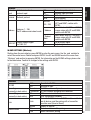
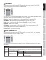
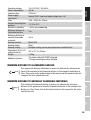
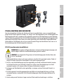
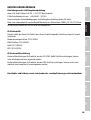
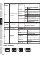
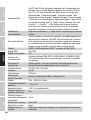
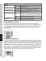
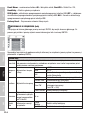
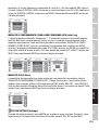
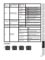
DIMMER CURVES
linear
DMX value
Light intensity
exponential
DMX value
Light intensity
logarithmic
DMX value
Light intensity
S-curve
DMX value
Light intensity
La pagina si sta caricando...
La pagina si sta caricando...
La pagina si sta caricando...
La pagina si sta caricando...
La pagina si sta caricando...
La pagina si sta caricando...
La pagina si sta caricando...
La pagina si sta caricando...
La pagina si sta caricando...
La pagina si sta caricando...
La pagina si sta caricando...
La pagina si sta caricando...
La pagina si sta caricando...
La pagina si sta caricando...
La pagina si sta caricando...
La pagina si sta caricando...
La pagina si sta caricando...
La pagina si sta caricando...
La pagina si sta caricando...
La pagina si sta caricando...
La pagina si sta caricando...
La pagina si sta caricando...
La pagina si sta caricando...
La pagina si sta caricando...
La pagina si sta caricando...
La pagina si sta caricando...
La pagina si sta caricando...
La pagina si sta caricando...
La pagina si sta caricando...
La pagina si sta caricando...
La pagina si sta caricando...
La pagina si sta caricando...
La pagina si sta caricando...
La pagina si sta caricando...
La pagina si sta caricando...
La pagina si sta caricando...
La pagina si sta caricando...
La pagina si sta caricando...
La pagina si sta caricando...
La pagina si sta caricando...
La pagina si sta caricando...
La pagina si sta caricando...
La pagina si sta caricando...
La pagina si sta caricando...
La pagina si sta caricando...
La pagina si sta caricando...
La pagina si sta caricando...
La pagina si sta caricando...
La pagina si sta caricando...
La pagina si sta caricando...
La pagina si sta caricando...
La pagina si sta caricando...
La pagina si sta caricando...
La pagina si sta caricando...
La pagina si sta caricando...
La pagina si sta caricando...
La pagina si sta caricando...
La pagina si sta caricando...
La pagina si sta caricando...
La pagina si sta caricando...
La pagina si sta caricando...
La pagina si sta caricando...
La pagina si sta caricando...
La pagina si sta caricando...
La pagina si sta caricando...
La pagina si sta caricando...
La pagina si sta caricando...
La pagina si sta caricando...
La pagina si sta caricando...
La pagina si sta caricando...
La pagina si sta caricando...
La pagina si sta caricando...
La pagina si sta caricando...
La pagina si sta caricando...
La pagina si sta caricando...
La pagina si sta caricando...
La pagina si sta caricando...
La pagina si sta caricando...
La pagina si sta caricando...
La pagina si sta caricando...
La pagina si sta caricando...
La pagina si sta caricando...
La pagina si sta caricando...
La pagina si sta caricando...
La pagina si sta caricando...
La pagina si sta caricando...
La pagina si sta caricando...
La pagina si sta caricando...
La pagina si sta caricando...
La pagina si sta caricando...
La pagina si sta caricando...
La pagina si sta caricando...
La pagina si sta caricando...
La pagina si sta caricando...
La pagina si sta caricando...
La pagina si sta caricando...
La pagina si sta caricando...
La pagina si sta caricando...
La pagina si sta caricando...
La pagina si sta caricando...
La pagina si sta caricando...
La pagina si sta caricando...
La pagina si sta caricando...
La pagina si sta caricando...
La pagina si sta caricando...
La pagina si sta caricando...
La pagina si sta caricando...
La pagina si sta caricando...
La pagina si sta caricando...
La pagina si sta caricando...
La pagina si sta caricando...
La pagina si sta caricando...
La pagina si sta caricando...
La pagina si sta caricando...
La pagina si sta caricando...
La pagina si sta caricando...
La pagina si sta caricando...
La pagina si sta caricando...
La pagina si sta caricando...
La pagina si sta caricando...
La pagina si sta caricando...
La pagina si sta caricando...
La pagina si sta caricando...
La pagina si sta caricando...
La pagina si sta caricando...
La pagina si sta caricando...
La pagina si sta caricando...
La pagina si sta caricando...
La pagina si sta caricando...
La pagina si sta caricando...
La pagina si sta caricando...
La pagina si sta caricando...
La pagina si sta caricando...
La pagina si sta caricando...
-
 1
1
-
 2
2
-
 3
3
-
 4
4
-
 5
5
-
 6
6
-
 7
7
-
 8
8
-
 9
9
-
 10
10
-
 11
11
-
 12
12
-
 13
13
-
 14
14
-
 15
15
-
 16
16
-
 17
17
-
 18
18
-
 19
19
-
 20
20
-
 21
21
-
 22
22
-
 23
23
-
 24
24
-
 25
25
-
 26
26
-
 27
27
-
 28
28
-
 29
29
-
 30
30
-
 31
31
-
 32
32
-
 33
33
-
 34
34
-
 35
35
-
 36
36
-
 37
37
-
 38
38
-
 39
39
-
 40
40
-
 41
41
-
 42
42
-
 43
43
-
 44
44
-
 45
45
-
 46
46
-
 47
47
-
 48
48
-
 49
49
-
 50
50
-
 51
51
-
 52
52
-
 53
53
-
 54
54
-
 55
55
-
 56
56
-
 57
57
-
 58
58
-
 59
59
-
 60
60
-
 61
61
-
 62
62
-
 63
63
-
 64
64
-
 65
65
-
 66
66
-
 67
67
-
 68
68
-
 69
69
-
 70
70
-
 71
71
-
 72
72
-
 73
73
-
 74
74
-
 75
75
-
 76
76
-
 77
77
-
 78
78
-
 79
79
-
 80
80
-
 81
81
-
 82
82
-
 83
83
-
 84
84
-
 85
85
-
 86
86
-
 87
87
-
 88
88
-
 89
89
-
 90
90
-
 91
91
-
 92
92
-
 93
93
-
 94
94
-
 95
95
-
 96
96
-
 97
97
-
 98
98
-
 99
99
-
 100
100
-
 101
101
-
 102
102
-
 103
103
-
 104
104
-
 105
105
-
 106
106
-
 107
107
-
 108
108
-
 109
109
-
 110
110
-
 111
111
-
 112
112
-
 113
113
-
 114
114
-
 115
115
-
 116
116
-
 117
117
-
 118
118
-
 119
119
-
 120
120
-
 121
121
-
 122
122
-
 123
123
-
 124
124
-
 125
125
-
 126
126
-
 127
127
-
 128
128
-
 129
129
-
 130
130
-
 131
131
-
 132
132
-
 133
133
-
 134
134
-
 135
135
-
 136
136
-
 137
137
-
 138
138
-
 139
139
-
 140
140
-
 141
141
-
 142
142
-
 143
143
-
 144
144
-
 145
145
-
 146
146
-
 147
147
-
 148
148
-
 149
149
-
 150
150
-
 151
151
-
 152
152
-
 153
153
-
 154
154


Cameo OPUS® SP5+ Manuale utente
- Categoria
- Proiettori
- Tipo
- Manuale utente
in altre lingue
- English: Cameo OPUS® SP5+ User manual
- français: Cameo OPUS® SP5+ Manuel utilisateur
- español: Cameo OPUS® SP5+ Manual de usuario
- Deutsch: Cameo OPUS® SP5+ Benutzerhandbuch
- polski: Cameo OPUS® SP5+ Instrukcja obsługi
Documenti correlati
-
Cameo OTOS® H5 Manuale utente
-
-
-
-
-
-
-
Cameo F2 FC IP Manuale utente
-
-