Deagostini HMS Bounty Admiralty Ship Guida utente
- Tipo
- Guida utente

PACK 04

PHASE PAGE
26 Cradle 106
27 Culverin 04 109
28 Theory - Beveled corners 110
29 Frame 11 118
30 Frame 12 122
31 Frame G 126
32 Frame H 130
33 Hawse Pieces 02 134
34 Lifeboat Yard 152
Design and production by Incipit srl
Assembly guide edited by Milanoedit srl - www.milanoedit.com
Published in Italy by De Agostini Publishing Italia S.p.A., 28100 Novara, Via G. da Verrazano 15
All rights reserved © 2020.
UNSUITABLE FOR CHILDREN UNDER 14. THE PRODUCT IS NOT A TOY
AND MUST BE USED UNDER ADULT SUPERVISION.
PARTS MAY BE DIFFERENT FROM THE PICTURED ONESW

PACK 04
105
ASSEMBLY INSTRUCTIONS
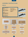
PACK 04
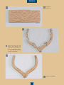
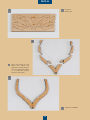
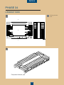
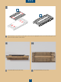
List of components
Cradle:
MDF board 4-08
Cantiere scialuppa:
MDF board 4-09
Frames:
wooden tablet 4-01
wooden tablet 4-02
wooden tablet 4-03
wooden tablet 4-04
Keel boat/pumps:
wooden tablet 4-07 *
Hawse Pieces:
wooden tablet 4-05
wooden tablet 4-06
2 culverins
2 forks
4-014-06
4-07 4-08 4-09
4-05
4-02
4-03 4-04
* Note: store tablet 4-07 with care, you will use it in the next packs.

PACK 04
106
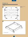
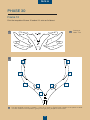
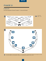
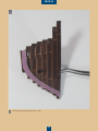
Completed cradle
1
2
3
4
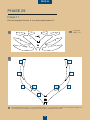
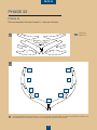
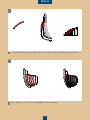
PHASE 26
Cradle
B
ADrawing of board
4-08.
A

PACK 04
107
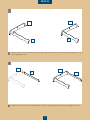
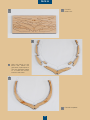
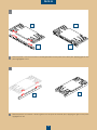
Detach pieces 1 and 2 from board 4-08 and glue them into the joints of the cradle by applying glue onto the
parts highlighted in red.
1
1
Detach piece 3 from board 4-08 and glue it to piece 1 by applying glue onto the part highlighted in red.
2
2
3
1
2
1
2
3
1
1

PACK 04
108
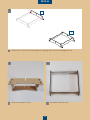
4
4
3
4 5
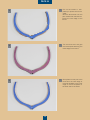
Detach piece 4 from board 4-08 and glue it by applying glue onto the part highlighted in red.
3
Completed cradle (front view).
4Completed cradle (top view).
5

PACK 04
109
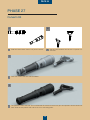
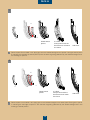
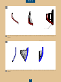
PHASE 27
Culverin 04
A
1
B
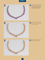
Side and axonometric view of 1/2 pound culverin.
A
Paint the culverin and fork with Gun Metal.
1
2
The painted culverin and fork. Do not assemble the culverin and the fork yet: this operation will be carried out
later. Store the two pieces with care so as not to risk losing them.
2
Side and axonometric view of the 1/2 pound cul-
verin fork.
B

PACK 04
110
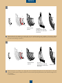
A
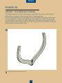
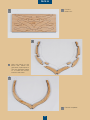
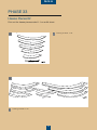
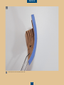
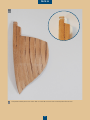
Drawing of the frame without beveled corner.
A
PHASE 28
THEORY - THE BEVELED CORNER
As already explained in Pack 03, the beveled corner allows the courses of the planking,
which rests on the frames of the bow and stern, to adhere perfectly.
To make the beveled corner, it is necessary to remove a portion of wood from each frame,
from the upper part to its lower tip. Depending on the length of the model, the exception
is for the frames in the centre of the ship, which often do not have the beveled corner. The
frames mostly involved in the beveled corner will be those of the bow and stern, where the
planking has more accentuated curves.

PACK 04
111
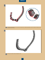
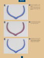
B
C
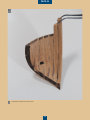
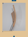
Drawing of the section to be removed from the frame to create the beveled corner. The section marked in red is
the part to be removed.
B
Drawing of the frame with the beveled corner.
C

PACK 04
112
E F G H I L
17 16 15 14 13 12 11 10 9 8 7
6 5 4 3 2 1 # A B C D
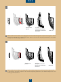
A
Drawing of side view of the ship.
A

PACK 04
113
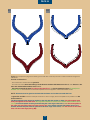
B1 B2
Figure A on the previous page is the drawing of the side view of the ship with the numbers and letters assigned to
the frames.
General considerations:
- the main frame is marked with the symbol #
- from the main frame, the frames that go to the bow are marked with letters from A to L, while those to - the
stern are marked with numbers from 1 to 17.
- the frames towards the bow (in red) from the letter E to L and those towards the stern (in green) from
number 7 to 17 are the frames to which the templates are to be applied to create the beveled corner.
NOTE: All frames must be glued to the keel with the letters and numbers towards the bow.
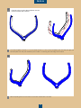
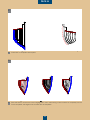
In gures B1 and B2 we have an example of frames on which to apply the two templates to be printed on an A4
sheet scaled 1:1.
The blue template must always be applied on the side with the number or letter; the red template must
always be applied on the other side. The important dierence is that on the frames with numbers (from
7 to 17) the blue template must be glued following the outer edge of the frame, while the red template on
the other side must follow the inner edge (see g. B1). In the frames marked with letters (from E to L),
instead, the blue template must be glued onto the inner edge of the frame, while the red one on the other
side, onto the outer edge (see g. B2).

PACK 04
114
PROFILO ESTERNO DIMA BLU COINCIDENTE CON PROFILO ESTERNO (ROSSO) SPIGOLO ORDINATA
PROFILO INTERNO DIMA ROSSA COINCIDENTE CON PROFILO INTERNO (ROSSO) SPIGOLO ORDINATA
PROFILO ESTERNO DIMA BLU COINCIDENTE CON PROFILO ESTERNO (ROSSO) SPIGOLO ORDINATA
PROFILO INTERNO DIMA ROSSA COINCIDENTE CON PROFILO INTERNO (ROSSO) SPIGOLO ORDINATA
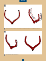
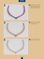
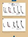
B
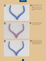
AExample of how to glue the templates onto the
frames marked with numbers
Blue template glued onto the frame on the side marked with a number.
B
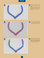
Print the template of frame 11 on an A4 sheet scaled 1:1. Cut out the templates (red and blue) and glue the
blue template onto the part marked by the number 11 following the outer edge of the frame.
A

PACK 04
115
PROFILO ESTERNO DIMA BLU COINCIDENTE CON PROFILO ESTERNO (ROSSO) SPIGOLO ORDINATA
PROFILO INTERNO DIMA ROSSA COINCIDENTE CON PROFILO INTERNO (ROSSO) SPIGOLO ORDINATA
PROFILO ESTERNO DIMA BLU COINCIDENTE CON PROFILO ESTERNO (ROSSO) SPIGOLO ORDINATA
PROFILO INTERNO DIMA ROSSA COINCIDENTE CON PROFILO INTERNO (ROSSO) SPIGOLO ORDINATA
D
C
The red template glued onto frame 11.
D
On the frames with numbers the red template must be glued following the inner edge of the other side.
C

PACK 04
116
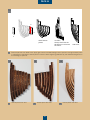
RIMUOVERE DIME
RASTREMAZIONE INTERMEDIA
RIMUOVERE DIME
RASTREMAZIONE INTERMEDIA
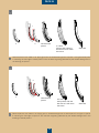
F
E
E1
F1
E2
F2
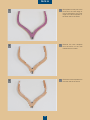
With the le begin to remove the outer corners of the frame from the outer corner of the blue template to the
outer corner of the red template glued onto the other side (g. E1). Then begin to remove the inner corners
of the frame from the inner corner of the red template to the inner corner of the blue template glued onto the
other side (g. E2).
E
Gently nish the operation with an abrasive sponge until a smooth surface is obtained between the external
and internal edges of the templates (gures F1 and F2).
F

PACK 04
117
RIMUOVERE DIME
RASTREMAZIONE INTERMEDIA
RIMUOVERE DIME
RASTREMAZIONE INTERMEDIA
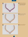
H
G
Frame 11 with the completed beveled edge (opposite side without number)
H
Frame 11 with the completed beveled edge (side with number)
G

PACK 04
118
B
A
2
3
4
5
7
69
8
1
19
2 8
3 7
4
5
6
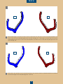
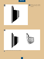
Drawing of
tablet 4-01
A
PHASE 29
Frame 11
Print the template of frame 11 onto an A4 sheet scaled 1:1.
Print the template of frame 11 on an A4 sheet scaled 1:1. In Figure B the numbers of the pieces of tablet 4-01
are marked on the template to give you the right gluing sequence of the frame.
B

PACK 04
119
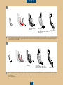
1
2
3
Glue the pieces of the
frame and before the
glue dries, superimpose it
onto the template scaled
1:1 to check the correct
course of the frame.
2
Frame 11
tablet 4-01.
1
Frame 11 completed.
3

PACK 04
120
4
6
5
Gently le the inner part of the
frame from the inner edge of
the blue template to the inner
edge of the red template on
the other side of the frame.
6
Turn the frame over and glue
on the red template following
the inside edge of the frame.
5
Cut out the scaled 1:1 tem-
plates you printed onto an A4
sheet.
Glue the blue template onto
the part marked with a number
following the outer edge of the
frame.
4

PACK 04
121
7
9
8
Gently le the outer part of the
frame from the outer edge of
the red template to the outer
edge of the blue template on
the other side of the frame.
7
Remove the blue template
from the frame on the side
marked with a number.
8
Remove the red template from
the other side of the frame.
9

PACK 04
122
B
A
2
3
4
57
6
9
8
1
19
28
37
4
5
6
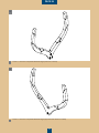
Drawing of
tablet 4-02
A
PHASE 30
Frame 12
Print the template of frame 12 scaled 1:1 onto an A4 sheet.
Print the template of frame 12 scaled 1:1 onto an A4 sheet. In Figure B the numbers of the pieces of tablet
4-02 are marked on the template to give you the right gluing sequence of the frame.
B
La pagina si sta caricando...
La pagina si sta caricando...
La pagina si sta caricando...
La pagina si sta caricando...
La pagina si sta caricando...
La pagina si sta caricando...
La pagina si sta caricando...
La pagina si sta caricando...
La pagina si sta caricando...
La pagina si sta caricando...
La pagina si sta caricando...
La pagina si sta caricando...
La pagina si sta caricando...
La pagina si sta caricando...
La pagina si sta caricando...
La pagina si sta caricando...
La pagina si sta caricando...
La pagina si sta caricando...
La pagina si sta caricando...
La pagina si sta caricando...
La pagina si sta caricando...
La pagina si sta caricando...
La pagina si sta caricando...
La pagina si sta caricando...
La pagina si sta caricando...
La pagina si sta caricando...
La pagina si sta caricando...
La pagina si sta caricando...
La pagina si sta caricando...
La pagina si sta caricando...
La pagina si sta caricando...
La pagina si sta caricando...
-
 1
1
-
 2
2
-
 3
3
-
 4
4
-
 5
5
-
 6
6
-
 7
7
-
 8
8
-
 9
9
-
 10
10
-
 11
11
-
 12
12
-
 13
13
-
 14
14
-
 15
15
-
 16
16
-
 17
17
-
 18
18
-
 19
19
-
 20
20
-
 21
21
-
 22
22
-
 23
23
-
 24
24
-
 25
25
-
 26
26
-
 27
27
-
 28
28
-
 29
29
-
 30
30
-
 31
31
-
 32
32
-
 33
33
-
 34
34
-
 35
35
-
 36
36
-
 37
37
-
 38
38
-
 39
39
-
 40
40
-
 41
41
-
 42
42
-
 43
43
-
 44
44
-
 45
45
-
 46
46
-
 47
47
-
 48
48
-
 49
49
-
 50
50
-
 51
51
-
 52
52


Deagostini HMS Bounty Admiralty Ship Guida utente
- Tipo
- Guida utente
in altre lingue
Documenti correlati
Altri documenti
-
Boston Whaler 250 Outrage Manuale del proprietario
-
 Hangar 9 HAN4770 Manuale del proprietario
-
Brother Innov-is XV8550D Manuale utente
-
ROBBE PAULA IV Building Instructions
-
Simrad MO Series Monitors Istruzioni per l'uso
-
-
Pulse Pacesetter BES Lettering 2 Manuale utente
-
 Hangar 9 HAN2990 Manuale del proprietario
-
Stovax Studio Air Profil Guida d'installazione

