Deagostini HMS Bounty Admiralty Ship Guida utente
- Tipo
- Guida utente

PACK 03

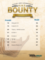
PHASE PAGE
18 Shipyard 03 59
19 Culverin 03 66
20 Theory - Mitred corner 67
21 Frame 5 75
22 Frame 6 77
23 Frame I 79
24 Frame L 83
25 Hawse Pieces 01 87
Design and production by Incipit srl
Assembly guide edited by Milanoedit srl - www.milanoedit.com
Published in Italy by De Agostini Publishing Italia S.p.A., 28100 Novara, Via G. da Verrazano 15
All rights reserved © 2020.
UNSUITABLE FOR CHILDREN UNDER 14. THE PRODUCT IS NOT A TOY
AND MUST BE USED UNDER ADULT SUPERVISION.
PARTS MAY BE DIFFERENT FROM THE PICTURED ONES

PACK 03
58
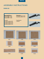
ASSEMBLY INSTRUCTIONS
PACK 03
Shipyard Base:
Board MDF 3-07
Board MDF 3-08
Board MDF 3-09
Frames:
wooden plate 3-01
wooden plate 3-02
wooden plate 3-03
wooden plate 3-04
Oarlocks:
wooden plate 3-05
wooden plate 3-06
2 culverins
2 forks
3-013-06
3-07 3-08 3-09
3-05
3-02
3-03 3-04

PACK 03
59
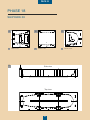
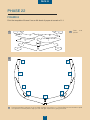
Side view
Top view
1
1
1
2 3
2
2
PHASE 18
SHIPYARD 03
A B C
D
Board 3-07
ABoard 3-08
BBoard 3-09
C

PACK 03
60
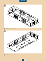
Axonometric view 2
Axonometric view 1
E
F
Shipyard - axonometric view 2
F
Shipyard - axonometric view 1
E

PACK 03
61
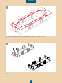
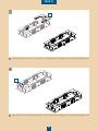
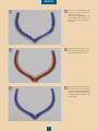
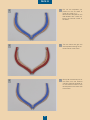
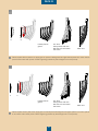
The parts highlighted in red are contained in Pack 3 (plates 3-07, 3-08 and 3-09).
1
1
Remove piece 2 from plate 3-07 and glue it to the shipyard joints, applying glue on the parts highlighted in red..
2
2
2

PACK 03
62
Remove piece 2 from plate 3-09 and glue it to the shipyard joints, applying glue on the parts highlighted in red.
3
3
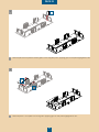
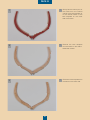
Remove piece 1 from plate 3-07 and glue it applying glue on the parts highlighted in red..
4
4
1
2
1a

PACK 03
63
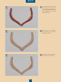
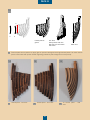
Remove piece 2 from plate 3-08 and glue it to the shipyard joints, applying glue on the parts highlighted in red.
5
5
Remove piece 1 from plate 3-08 and glue it to the shipyard joints, applying glue on the parts highlighted in red.
6
6
2
1

PACK 03
64
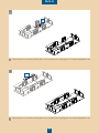
Remove piece 1 from plate 3-09 and glue it to the shipyard joints, applying glue on the parts highlighted in red.
8
8
Remove piece 3 from plate 3-07 and glue it to the shipyard joints, applying glue on the parts highlighted in red.
7
7
1
3

PACK 03
65
9
10
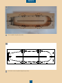
The completed shipyard (top view).
9
10 Picture of the completed shipyard (top view).
10

PACK 03
66
PHASE 19
CULVERIN 03
A
1
B
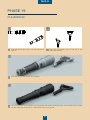
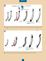
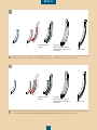
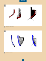
Side and axonometric view of the the half-pound
culverin.
A
Paint the culverin and the fork in Gun Metal.
1
2
The culverin and the fork painted. Do not assemble the culverin and the fork yet: this operation will be carried
out later. Keep the two pieces in a safe placeso they won’t get lost .
2
Side and axonometric view of the fork of the
half-pound culverin.
B

PACK 03
67
A
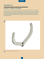
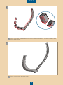
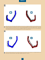
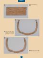
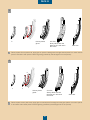
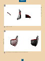
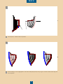
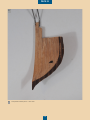
Picture of the frame without mitred corner.
A
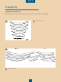
PHASE 20
THEORY - MITRED CORNER
The mitred corner allows plating, which lays on the bow and stern frames, to t perfectly.
To carry out the mitred corner, a wooden section of each frame is to be removed from the
top to the bottom end. According to the length of the model, the frames at the centre of
the ship can make an exception as they often do not have a mitred corner. The frames
most involved in the mitred corner are the bow and stern ones, where plating has more
emphasized bends.

PACK 03
68
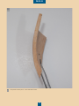
B
C
Picture of the section to be removed from the frame to make the mitred corner. The section marked in red is
the part to be removed.
B
Picture of the frame with the mitred corner.
C

PACK 03
69
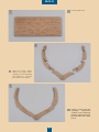
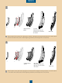
E F G H I L
17 16 15 14 13 12 11 10 9 8 7
6 5 4 3 2 1 # A B C D
A
Picture of the ship - side view.
A

PACK 03
70
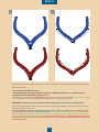
B1 B2
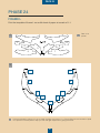
Picture A on the previous page is the picture of the ship’s side view with numbers and letters assigned to the frames.
General observations:
- the main frame is labelled by sign #
- from the main frame the frames towards the bow are labelled by letters A to L, whereas the ones
towards the stern are labelled by numbers 1 to 17.
- the frames towards the bow (in red) from letters E to L, and the ones towards the stern (in green) from numbers
7 to 17, are the frames Pack 03 templates are to be applied to, to make the mitred corner.
REMEMBER: all the frames are to be glued to the keel with letters and numbers towards the bow.
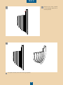
Pictures B1 and B2 display a sample of frames where the two paper templates are to be applied and printed on an
A4 sheet of paper at a scale of 1:1.
The blue template is always to be applied on the side of the number or the letter; the red template is always
to be applied on the other side. The main dierence is: in the frames with numbers (7-17) the blue template
is to be glued following the external outline of the frame, whereas the red template on the other side has to
follow the internal outline (see picture B1). ). In the frames with letters (E - L), the blue template is to be glued
on the internal outline of the frame, whereas the red one on the other side is to be glued on the external outli-
ne (see picture B2).

PACK 03
71
PROFILO INTERNO DIMA BLU COINCIDENTE CON SPIGOLO
(ROSSO) INTERNO ORDINATA
PROFILO ESTERNO DIMA ROSSA COINCIDENTE CON
SPIGOLO (ROSSO) ESTERNO ORDINATA
PROFILO INTERNO DIMA BLU COINCIDENTE CON SPIGOLO
(ROSSO) INTERNO ORDINATA
PROFILO ESTERNO DIMA ROSSA COINCIDENTE CON
SPIGOLO (ROSSO) ESTERNO ORDINATA
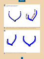
B
AAn example of how to glue the tem-
plates on the frames with letters.
Blue template glued to the frame on the side labelled with a letter.
B
Print the template of frame L on an A4 sheet of paper at a scale of 1:1. Cut out the templates (red and blue)
and glue the blue template from letter L side following the internal outline of the frame (picture A).
A

PACK 03
72
PROFILO INTERNO DIMA BLU COINCIDENTE CON SPIGOLO
(ROSSO) INTERNO ORDINATA
PROFILO ESTERNO DIMA ROSSA COINCIDENTE CON
SPIGOLO (ROSSO) ESTERNO ORDINATA
PROFILO INTERNO DIMA BLU COINCIDENTE CON SPIGOLO
(ROSSO) INTERNO ORDINATA
PROFILO ESTERNO DIMA ROSSA COINCIDENTE CON
SPIGOLO (ROSSO) ESTERNO ORDINATA
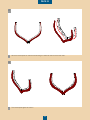
D
C
The red template glued to frame L.
D
Glue the red template on the frames following the external outline of the other side.
C

PACK 03
73
PROFILO INTERNO DIMA BLU COINCIDENTE CON SPIGOLO
(ROSSO) INTERNO ORDINATA
PROFILO ESTERNO DIMA ROSSA COINCIDENTE CON
SPIGOLO (ROSSO) ESTERNO ORDINATA
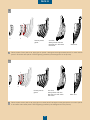
rastremazione
intermedia
rimuovere le dime
PROFILO INTERNO DIMA BLU COINCIDENTE CON SPIGOLO
(ROSSO) INTERNO ORDINATA
PROFILO ESTERNO DIMA ROSSA COINCIDENTE CON
SPIGOLO (ROSSO) ESTERNO ORDINATA
rastremazione
intermedia
rimuovere le dime
F
E
E1
F1
E2
F2
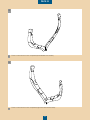
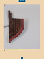
Finish the operation gently with an abrasive sponge until you get a smooth surface at 45 degrees between the
external and internal outlines of the paper templates (pictures F1 and F2).
With the le, start removing the frame external corners with a 45 degree inclination from the external corner of
the blue template up to the external corner of the red template glued on the other side (picture E1). Then start
removing the frame internal corners with a 45 degree inclination from the internal corner of the red template up
to the internal corner of the blue template glued on the other side (picture E2).
E
F

PACK 03
74
PROFILO INTERNO DIMA BLU COINCIDENTE CON SPIGOLO
(ROSSO) INTERNO ORDINATA
PROFILO ESTERNO DIMA ROSSA COINCIDENTE CON
SPIGOLO (ROSSO) ESTERNO ORDINATA
rastremazione
intermedia
rimuovere le dime
PROFILO INTERNO DIMA BLU COINCIDENTE CON SPIGOLO
(ROSSO) INTERNO ORDINATA
PROFILO ESTERNO DIMA ROSSA COINCIDENTE CON
SPIGOLO (ROSSO) ESTERNO ORDINATA
rastremazione
intermedia
rimuovere le dime
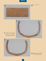
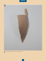
H
G
Frame L with mitred corner completed (opposite side without letter).
H
Frame L with mitred corner completed (side labelled with a letter).
G

PACK 03
75
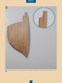
B
A
2
3
4
5
7
6
9
8
1
19
28
37
4
5
6
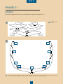
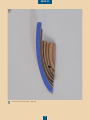
Plate 3-01
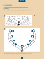
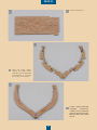
picture.
A
PHASE 21
FRAME 5
Print the template of frame 5 on an A4 sheet of paper at a scale of 1:1.
Print the template of frame 5 on an A4 sheet of paper at a scale of 1:1. Picture B shows the numbers of plate
3-01 pieces on the template to help you with the right sequence for gluing the frame.
B
La pagina si sta caricando...
La pagina si sta caricando...
La pagina si sta caricando...
La pagina si sta caricando...
La pagina si sta caricando...
La pagina si sta caricando...
La pagina si sta caricando...
La pagina si sta caricando...
La pagina si sta caricando...
La pagina si sta caricando...
La pagina si sta caricando...
La pagina si sta caricando...
La pagina si sta caricando...
La pagina si sta caricando...
La pagina si sta caricando...
La pagina si sta caricando...
La pagina si sta caricando...
La pagina si sta caricando...
La pagina si sta caricando...
La pagina si sta caricando...
La pagina si sta caricando...
La pagina si sta caricando...
La pagina si sta caricando...
La pagina si sta caricando...
La pagina si sta caricando...
La pagina si sta caricando...
La pagina si sta caricando...
La pagina si sta caricando...
La pagina si sta caricando...
-
 1
1
-
 2
2
-
 3
3
-
 4
4
-
 5
5
-
 6
6
-
 7
7
-
 8
8
-
 9
9
-
 10
10
-
 11
11
-
 12
12
-
 13
13
-
 14
14
-
 15
15
-
 16
16
-
 17
17
-
 18
18
-
 19
19
-
 20
20
-
 21
21
-
 22
22
-
 23
23
-
 24
24
-
 25
25
-
 26
26
-
 27
27
-
 28
28
-
 29
29
-
 30
30
-
 31
31
-
 32
32
-
 33
33
-
 34
34
-
 35
35
-
 36
36
-
 37
37
-
 38
38
-
 39
39
-
 40
40
-
 41
41
-
 42
42
-
 43
43
-
 44
44
-
 45
45
-
 46
46
-
 47
47
-
 48
48
-
 49
49


Deagostini HMS Bounty Admiralty Ship Guida utente
- Tipo
- Guida utente
in altre lingue
Documenti correlati
Altri documenti
-
Brother Innov-is XV8550D Manuale utente
-
Boston Whaler 250 Outrage Manuale del proprietario
-
 Hangar 9 HAN4770 Manuale del proprietario
-
ROBBE PAULA IV Building Instructions
-
Evolution EVOE10GX Manuale utente
-
-
 Hangar 9 HAN4720CR Manuale del proprietario
-
Pulse Pacesetter BES Lettering 2 Manuale utente
-
 Hangar 9 HAN2990 Manuale del proprietario
-
 Hangar 9 HAN2765 Manuale del proprietario


