Carel pGDx Series Assembly And Installation
- Tipo
- Assembly And Installation

+050001555 - rel. 1.0 date 05.05.2020
Descrizione
I terminali graci pGDx da 10 e 15 pollici appartengono alla famiglia
di terminali touch screen pensata per rendere semplice e intuitivo
interfacciamento dell’utente con i controlli delle famiglie pCO e c.pCO
Sistema. La tecnologia dei nuovo display ad alta risoluzione, insieme
ad una gamma cromatica pari a 16 milioni garantisce un’interfaccia
graca di alto livello. Caratteristica trasmessa anche dallo schermo di
vetro al quale è accoppiato una tecnologia touch capacitiva, capace
di restituire il feeling tipici di cellulari / tablet. Permettono di gestire
immagini ad alta risoluzione e funzionalità avanzate per ottenere un
elevato standard estetico.
Codici modelli
Codice Dimensione display Risoluzione
PGB10010FCCA0 10.1 pollici 1280x800 (WXGA)
PGB15010FCCA0 15.6 pollici 1366x768 (HD)
Codici accessori
Codice Descrizione
PGTA00TRF0 Alimentatore 230 VAC – 24 VDC per guida DIN
Avvertenze per l’installazione
Evitare il montaggio delle schede in ambienti che presentino le
seguenti caratteristiche:
• umidità relativa maggiore di quanto indicato nelle speciche
tecniche;
• forti vibrazioni o urti;
• esposizione ad atmosfere aggressive ed inquinanti (es.: gas solforici
e ammoniacali, nebbie saline, fumi) con conseguente corrosione e/o
ossidazione;
• elevate interferenze magnetiche e/o radiofrequenze (evitare quindi
l’installazione delle macchine vicino ad antenne trasmittenti);
• esposizione all’irraggiamento solare diretto e agli agenti atmosferici
in genere;
• ampie e rapide uttuazioni della temperatura ambiente;
• ambienti ove sono presenti esplosivi o miscele di gas inammabili;
• evitare di avvicinarsi con le dita ai componenti elettronici montati
sulle schede per evitare scariche elettrostatiche (estremamente
dannose) dall’operatore verso i componenti stessi.
Avvertenze generali
1. I terminale pGDTouch 10’’ e 15’’ possono essere alimentati solo in
corrente continua.
2. Una tensione di alimentazione elettrica diversa da quella prescritta
può danneggiare seriamente il sistema;
3. Utilizzare capicorda adatti per i morsetti in uso. Allentare ogni vite
ed inserirvi i capicorda, quindi serrare le viti. Ad operazione ultimata
tirare leggermente i cavi per vericarne il corretto serraggio;
4. L’uso a temperature particolarmente basse può causare una visibile
diminuzione della velocità di risposta del display. Questo è da
ritenersi normale e non è indice di malfunzionamento.
Primo avvio
Al momento dell’avvio, il terminale mostrerà una schermata di scelta tra
la modalità Runtime o la modalità Browser.
Aggiornamento HMI Runtime e/o applicazione
Copiare il pacchetto di aggiornamento (le
.ZIP) contenente il runtime o l’applicazione,
oppure entrambi, a seconda delle opzioni
scelte al momento della generazione di
“Update package” con c.touch, in una
chiavetta USB e successivamente collegare
la chiavetta al pGDx. Tenere premuto il
dito sullo schermo del terminale pGDx
per alcuni secondi no a che il menu
contestuale sarà visualizzato, disabilitabile
lato applicativo (Fig. a lato):
Selezionare “Update…” per avviare
la procedura di aggiornamento
Runtime e/o applicazione. L’utility
per l’aggiornamento si avvierà ed
apparirà la seguente nestra:
Seguire quindi la procedura guidata selezionando il le inserito nella
chiavetta USB e premendo il tasto next per conferma.
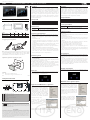
Installazione e montaggio /
Assembly and installation
Dimensioni e forature /
Dimensions & drilling template
(in mm/inc.)
H
L
A
B
C
8mm
0.31”
Fig.1
Model A B C H L
PGB10010FCCA0 271mm/
10.66”
186mm/
07.32”
56mm/
02.20”
197mm/
07.75”
282mm/
11.10”
PGB15010FCCA0 411mm/
16.18”
256mm/
10.00”
56mm/
02.20”
267mm/
10.50”
422mm/
16.60”
Tab. 1
Fissaggio supporti /
Fixing bracket
Fig.2
Nota: avvitare ogni vite di ssaggio no a quando l’angolo della cornice poggerà
sul pannello (Rif.: PGB10010FCCA0: 9 Pezzi; PGB15010FCCA0: 12 Pezzi). /
Tighten
each xing screw until the corner of the frame comes into contact with the
panel (Ref.: PGB10010FCCA0: 9 Pieces; PGB15010FCCA0: 12 Pieces).
Applicazione guarnizione /
Applying the gasket
1
2
Fig.3
Legenda :
PGB10010FCCA0; PGB15010FCCA0
Foratura per il montaggio /
Installation knock-out
Tab. 2
Vista posteriore/ Rear view
Fig.4
USB port V2.0, max. 500 mA
Ethernet port 2 (10/100 Mb), non utilizzabile /
not usable
Ethernet port 1 (10/100 Mb)
Serial port
Ethernet port 0 (10/100/1000 Mb)
Power supply
SD Card Slot
Tab. 2
Alimentazione /
Power supply
Terminale utente pGDx10” / 15” -
pGDx 10” / 15” user terminal
pGDx
Description
The pGDx 10” and 15” graphic terminals are part of the touch screen
family, designed to make the user interface with the pCO/c.pCO
controllers simple and intuitive. The technology used on the high-
resolution display, with 16 million colours, guarantees a high-level
graphic interface. The glass screen, together with capacitive touch
technology, give the user the typical feeling of mobile phones/tablets.
These features mean high resolution images and advanced functions
can be managed, all with a high aesthetic standard.
Model part numbers
P/N Display size Resolution
PGB10010FCCA0 10.1 inches 1280x800 (WXGA)
PGB15010FCCA0 15.6 inches 1366x768 (HD)
Accessory part numbers
P/N Description
PGTA00TRF0 230 VAC – 24 VDC power supply for DIN rail
Installation warnings
Do not install the boards in environments with the following
characteristics:
• relative humidity greater than the value specied in the technical
specications;
• strong vibrations or knocks;
• exposure to aggressive and polluting atmospheres (e.g.: sulphur and
ammonia fumes, saline mist, smoke) so as to avoid corrosion and/or
oxidation;
• strong magnetic and/or radio frequency interference (therefore
avoid installing the units near transmitting antennae);
• exposure to direct sunlight or the elements in general;
• large and rapid uctuations in the room temperature;
• environments where explosives or mixes of ammable gases are
present;
• avoid touching or nearly touching the electronic components tted
on the boards to avoid electrostatic discharges (extremely damaging)
from the operator to the components.
General warnings
1. The pGD Touch 10” and 15” terminals are for DC power supply only.
2. Power supplies other than those specied may seriously damage the
system;
3. Use cable ends suitable for the corresponding terminals. Loosen
each screw and insert the cable ends, then tighten the screws. When
nished, slightly tug the cables to check they are suciently tight.
4. Operation at low temperatures may cause a visible decline in the
response speed of the display. This should be considered normal and
does not indicate a malfunction.
Switching on the first time
At startup, the terminal will show a screen to select Runtime mode or
Browser mode.
HMI Runtime and/or application update
Copy the update package (.ZIP le)
containing the runtime or application, or
both, depending on the options selected
when generating the “Update package”
using c.touch, to a USB pen drive and then
plug the pen drive into the pGDx and hold
the pGDx terminal screen for a few seconds
until the shortcut menu is displayed; this
can be disabled in the application (see the
gure on the side):
Select “Update…” to start the Runtime
and/or application update procedure.
The update utility will start and the
following window will be displayed:
Then follow the guided procedure, selecting the le saved on the USB
pen drive and clicking the next button to conrm.
IMPORTANT WARNINGS
The CAREL product is a state-of-the-art product, whose operation is specied in the technical documentation supplied with
the product or can be downloaded, even prior to purchase, from the website www.carel.com. - The customer (manufacturer,
developer or installer of the nal equipment) accepts all liability and risk relating to the conguration of the product in order to
reach the expected results in relation to the specic nal installation and/or equipment. Failure to complete such operations,
which are required/indicated in the user manual, may cause the nal product to malfunction; CAREL accepts no liability in such
cases. The end customer must only use the product in the manner described in the documentation relating to the product. The
liability of CAREL in relation to its products is specied in the CAREL general contract conditions, available on the website www.
carel.com and/or by specic agreements with customers.
NO POWER
& SIGNAL
CABLES
TOGETHER
READ CAREFULLY IN THE TEXT!
WARNING: separate as much as possible the probe and digital input signal cables from the cables carrying
inductive loads and power cables to avoid possible electromagnetic disturbance. Never run power cables (including the electrical
panel wiring) and signal cables in the same conduits.

CAREL Industries HQs
Via dell’Industria, 11 - 35020 Brugine - Padova (Italy)
Tel. (+39) 0499716611 – Fax (+39) 0499716600 – www.carel.com – e-mail: [email protected]
Alimentatore a bassissima tensione di sicurezza/sorgente di potenza
limitata /
Extra low voltage power supply / Limited power source.
+24 V
0V
+24 V
0V
Fig.5
Non aprire l’involucro dei pannelli quando sono alimentati /
Do not open
the panel rear cover when power is connected.
+24 V
0V
connettere a terra con un faston
L
N
N
L
+V
-V
100-240 Vac
PGTA00TRF0
PGDx10/15
Rear panel
Fig.6
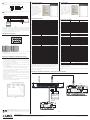
Vericare che l’alimentatore sia in grado di erogare la potenza necessaria per il
corretto funzionamento dell’apparecchiatura. E’ possibile ordinare l’alimentatore
230Vac/24Vdc - codice PGTA00TRF0. /
Ensure that the power supply has enough
power capacity for the operation of the devices
.
The 230 Vac/24Vdc power
supply - part number PGTA00TRF0 can be ordered.
Collegamenti / Connections
SERIAL PORT
1
7
82
Fig.7
Pin Description Pin Description
1 RX/CHB - 5 +5V output
2 TX/CHA - 6 GND
3 CTS/CHB+ 7
4 RTS/CHA+ 8 SHIELD
Nota /Note:
Per operare in RS-485: i pin 1-2 e 3-4 devono essere collegati
esternamente.
To use RS-485: pins 1-2 and 3-4 must be connected externally
Regole per lo smaltimento /
Guidelines for disposal
• Non smaltire il prodotto come riuto solido urbano ma smaltirlo negli
appositi centri di raccolta.
• Il prodotto contiene una batteria ed è quindi necessario rimuoverla
separandola dal resto del prodotto seguendo le istruzioni riportate di seguito
prima di procedere al suo smaltimento.
• Un uso improprio o uno smaltimento non corretto potrebbe avere eetti
negativi sulla salute umana e sull’ambiente.
• Per lo smaltimento vanno utilizzati i sistemi di raccolta pubblici o privati
previsti dalle leggi locali.
• In caso di smaltimento abusivo dei riuti elettrici ed elettronici sono previste
sanzioni stabilite dalle vigenti normative locali in materia di smaltimento.
•
Do not dispose of the product as municipal waste; it must be disposed of
through specialist waste disposal centres.
•
The product contains a battery that must be removed and separated from the
rest of the product according to the instructions provided, before disposing
of the product.
•
Improper use or incorrect disposal of the product may negative eects on
human health and on the environment.
•
The public or private waste collection systems dened by local legislation
must be used for disposal.
•
In the event of illegal disposal of electrical and electronic waste, the penalties
are specied by local waste disposal legislation.
Fig. 8
Impostazioni di sistema
Tenere premuto il
dito sullo schermo del
terminale pGDx per
alcuni secondi no a
che il menu contestuale
sarà visualizzato (g.
sotto), Selezionare “Show
system settings”, apparirà
la schermata principale
del programma di
congurazione (g a
lato):
Caratteristiche tecniche
Dispaly 10" 15"
Tipo LCD TFT LCD TFT
Risoluzione 1280x800, WXGA 1366x768, HD
Area attiva del display 10.1“ diagonale 15,6“ diagonale
Colori 16.7M 16.7M
Retro-illuminazione LED - Lifetime 40 khrs @ 25 °C
Regolazione luminosità Si - auto spegnimento congurabile
Luminosità (tipico) 500 Cd/m2 typ. 400 Cd/m2 typ.
Interfaccia utente
Touchscreen True Glass Projected Capacitive, Multitouch
Indicatori LED sistema Non presente
Interfacce
Porte Ethernet ETH0, ETH1 2 (ETH0 -10/100/1000, ETH1-10/100, ETH 2-not
usable)
Wi-Fi Non Disponibile
Porta USB (1) Host interface 2.0 - USB -A - 500 mA max (non
utilizzare per ricaricare dispositivi) Lmax = 1m
Porte Seriali (1) 1 RS-485
Sonda temper. /umidità Non Disponibile
SD card disponibile
Funzionalità
Grafca vettoriale Si, incluso supporto SVG 1.0
Oggetti dinamici Si Visibilità, posizione, rotazione
TrueType fonts Si
Multiprotocollo Modbus RTU/TCP
Storico e trend Si. Limitato alla capacità della Flash memory
Multi-lingue Si, con impostazione della lingua run-time e
limitato solo dalla memoria disponibile
Recipes (ricette) Si. Limitato alla capacità della Flash memory
Allarmi Si
Lista event Si
Passwords Si
Real Time Clock Si, con batteria di back-up
Buzzer presente
Elettriche
Alimentazione 24 Vdc (da 10 a 32 Vdc)
Max potenza assorbita 24 W 29 W
Fusibile Automatico
Peso 2,5 Kg 4,1 Kg
Batteria Batteria al litio ricaricabile, non sostituibile
dall'utente
Condizioni ambientali
Temperatura di lavoro -20T60 °C -20T60 °C
Temperatura di immagaz. -30T70 °C -30T70 °C
Umidità relativa max di
lavoro e immagaz.
5- 85% RH non-
condensante
5- 85% RH non-
condensante
Grado di protezione IP66 (frontale), IP20 (retro) IP66 (front.), IP20 (retro)
L’utilizzo di queste apparecchiature in ambienti residenziali, commerciali
e dell’industria leggera è permesso solo nel caso in cui vengano prese
le misure speciali per ottenere la conformità alla IEC61000-6-3.
CAREL si riserva la possibilità di apportare modiche o cambiamenti ai propri
prodotti senza alcun preavviso.
Smaltimento del prodotto: l’apparecchiatura (o il prodotto) deve essere oggetto
di raccolta separata in conformità alle vigenti normative locali in materia di
smaltimento. /
Disposal of the product: the appliance (or the product) must be
disposed of separately in accordance with the local waste disposal legislation in
force.
+050001555 - rel. 1.0 date 05.05.2020
Schema per collegamento a pCO/c.pCO /
pCO/c.pCO connection diagram
C1
NO1
NO2
NO3
C1
C4
NO4
NO5
NO6
C4
C7
NO7
C7
NO8
C8
NC8
G
G0
U1
U2
U3
GND
+VDC
U4
GND
U5
GND
VG
VG0
Y1
Y2
Y3
Y4
ID1
ID2
ID3
ID4
ID5
ID6
ID7
ID8
IDC1
J1
J2
J3
J4
J5
J14
J10
J13
J12
J15
drac SMBdrac suBdleiF
4 3 2 1
Tx/Rx
J11 pLAN
GND
J25 BMS2
Tx/Rx
GND
Tx/Rx
GND
J26 FBus2
+Vterm
GND
+5VREF
J24
+
XXXXXXXXXXXX
J1
J2
J3
J4 J5
J14
J10
J13
J12
J15
drac SMBdrac suBdleiF
4 3 2 1
J11 pLAN
Tx/Rx
GND
J26 FBus2
J24
+
XXXXXXXXXXXX
c.pCO/pCO
J25 BMS2
GND
-
+
L
N
N
L
+V
-V
100-240 Vac
PGTA00TRF0
c.pCO
Fig. 9
System settings
Touch and hold the
pGDx terminal screen
for a few seconds until
the shortcut menu
is displayed (see the
gure below). Select
“Show system settings”;
the main conguration
program screen will be
displayed (gure on the
side):
Technical specifications
Display 10" 15"
Type LCD TFT LCD TFT
Resolution 1280x800, WXGA 1366x768, HD
Active display area 10.1” diagonal 15.6” diagonal
Colours 16.7M 16.7M
Backlight LED - Lifetime 40 khrs @ 25 °C
Brightness Yes - congurable auto power-o
Brightness (typical) 500 Cd/m2 typ. 400 Cd/m2 typ.
User interface
Touchscreen True Glass Projected Capacitive, Multitouch
System LED indicators Not present
Interfaces
Ethernet ports ETH0, ETH1 2 (ETH0 -10/100/1000, ETH1-10/100, ETH 2-not
usable)
Wi-Fi Not available
USB Port (1) Host interface 2.0 - USB -A - 500 mA max (do not
use to charge devices) Lmax = 1m
Serial Port (1) 1 RS-485
Temp. /humidity probe Not available
SD card Available
Functions
Vector graphics Yes, includes SVG 1.0 support
Object dynamics Yes Visibility, position size, rotation
TrueType fonts Yes
Multiple driver commun. Modbus RTU/TCP
Data acquisition
and trend presentation
Yes. Limited based on ash memory storage capacity
Multilanguage
Yes, number of run-time languages limited by
available memory
Recipes Yes. Limited based on ash memory storage capacity
Alarms Yes
Event list Yes
Passwords Yes
Real Time Clock Yes, with backup battery
Buzzer Present
Ratings
Power supply 24 Vdc (10 to 32 Vdc)
Current draw 24 W 29 W
Fuse Automatic
Weight 2.5 kg 4.1 kg
Battery Rechargeable Lithium battery, not user-replaceable
Environmental conditions
Operating temperature -20T60 °C
Storage temperature -30T70 °C
Operating and storage
humidity
5-85% RH non-condensing
Index of protection IP66 (front), IP20 (rear)
These devices can only be used in residential, commercial and light
industrial environments if special measures are taken to ensure
conformity to IEC61000-6-3.
CAREL reserves the right to modify the features of its products without prior
notice.
-
 1
1
-
 2
2


Carel pGDx Series Assembly And Installation
- Tipo
- Assembly And Installation
in altre lingue
- English: Carel pGDx Series
Documenti correlati
-
Carel pGD3 Technical Leaflet
-
Carel PGB10010FA0D0 Manuale utente
-
-
-
Carel J3 Manuale utente
-
-
-
-
-