Carel tERA Connect Box 2G/3G Assembly And Installation
- Tipo
- Assembly And Installation

+050001038 - rel. 1.0 - 18/05/2017
tERA Connect Box 2G/3G
Introduzione
Il dispositivo tERA Connect Box 2G/3G appartiene alla
famiglia dei dispositivi di connettività per la supervisione
remota di impianti HVAC/R. tERA Connect Box 2G/3G
permette di collegare una rete di controlli di macchina
alla piattaforma web tERA tramite connessione 2G/3G.
Contenuto confezione
• tERA Connect Box 2G/3G;
• connettori alimentazione e RS485;
• antenna 2G/3G;
• foglio istruzioni.
Avvertenze per l’installazione
Prima di installare il prodotto veri care che la zona
sia coperta adeguatamente dal segnale 2G/3G. Per
una installazione a regola d’arte rivolgersi ad installatori
abilitati. Evitare il montaggio del prodotto in ambienti che
presentino le seguenti caratteristiche:
• umidità relativa maggiore di quanto indicato nelle
specifi che tecniche;
• forti vibrazioni o urti;
• esposizione ad atmosfere aggressive ed inquinanti (es.:
gas solforici e ammoniacali, nebbie saline, fumi) con
conseguente corrosione e/o ossidazione;
• elevate interferenze magnetiche e/o radiofrequenze
(evitare quindi l’installazione delle macchine vicino ad
antenne trasmittenti);
• esposizione all’irraggiamento solare diretto e agli
agenti atmosferici in genere;
• ampie e rapide fl uttuazioni della temperatura ambiente;
• ambienti ove sono presenti esplosivi o miscele di gas
infi ammabili.
Devono essere rispettate le seguenti prescrizioni:
• ATTENZIONE: Per il collegamento elettrico rispettare
la polarità indicata in Fig. 6 e sul connettore incluso
nella scatola;
• posizionare l’antenna al di fuori di carpenterie
metalliche;
• per la rete di comunicazione RS485 utilizzare
esclusivamente cavi schermati;
• una tensione di alimentazione elettrica diversa da
quella prescritta può danneggiare seriamente il
sistema;
• utilizzare capicorda adatti per i morsetti in uso. Allentare
ogni vite ed inserirvi i capicorda, quindi serrare le viti.
Ad operazione ultimata tirare leggermente i cavi per
verifi carne il corretto serraggio;
• non aprire il prodotto quando è alimentato.
Veri ca dell’alimentazione
Led Verde/Green Led = Alimentato correttamente
Led Spento = Non alimentato
Veri ca del collegamento piattaforma web
tERA
Buzzer veloce (5 beep/sec) = mancanza segnale 2G/3G
Buzzer lento (1beep/sec) = collegamento piattaforma
web tERA non riuscito
Beep singolo (1sec) = Il collegamento è OK.
Veri ca dell’installazione
Collegarsi tramite PC o tablet alla piattaforma tERA,
accedere al menù “Confi gurazione” e seguire la procedura.
Se richiesto dalla
procedura inserire
il Serial Number e il
Security Code indicati
nell’etichetta del
prodotto.
ATTENZIONE: solo quando tutti i controlli della linea
sono stati rilevati correttamente è possibile concludere
l’installazione e abbandonare l’impianto.
Installazione e montaggio
Assembly and installation
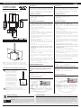
Dimensioni e forature (in mm/inc.)
Dimensions and drilling template (in mm/inc.)
106
168
161
RZ
54
R 6
54
170
198
150
182
152,2
20
344,3
Fig.1
H mm (inc) W mm (inc) P mm (inc)
Dimensioni/
Dimensions
344,3 (13,55) 182 (7,16) 54 (2,13)
Foratura/
Drilling template
17 (4,21) 173 (6,81) -
Tab. 1
Fig.2
Nota: avvitare ogni vite di fi ssaggio fi no a quando l’angolo
della cornice poggerà sul pannello. /
Screw each fi xing
screw until the bezel corner gets in contact with the panel.
Sostituzione batteria /
Battery replacement:
Per accedere alla batteria per la
sostituzione o lo smaltimento,
è necessario disalimentare
il dispositivo e rimuovere il
coperchio superiore (svitare
le 4 viti laterali). Utilizzare
batterie al litio mod BR2330
(non ricaricabili). /
To access
the battery for replacement
or disposal, power down the
device and remove the front
cover (remove the 4 screws
on right and lefts sides).
Use model BR2330 lithium
batteries (non-rechargeable).
Fig. 3
Attenzione! sussiste il pericolo d’esplosione se la
batteria e’ sostituita con altre di tipo errato.
Warning! danger of explosion if an incorrect battery
is used.
Introduction
The tERA Connect Box 2G/3G device belongs to the
family of connectivity devices for remote supervision
of HVAC/R systems. tERA Connect Box 2G/3G is used to
connect a network of unit controllers to the tERA web
platform with 2G/3G connection.
Packaging contents
• tERA Connect Box 2G/3G;
• power supply and RS485 connectors;
• 2G/3G antenna;
• instruction sheet.
Installation warnings
Before installing the product make sure the area is
su ciently covered by a 2G/3G signal. For correct
installation contact a qualifi ed installer. Do not
install products in environments with the following
characteristics:
• relative humidity greater than the value specifi ed in the
technical specifi cations;
• strong vibrations or knocks;
• exposure to aggressive and polluting atmospheres
(e.g.: sulphur and ammonia fumes, saline mist, smoke)
so as to avoid corrosion and/or oxidation;
• strong magnetic and/or radio frequency interference
(therefore avoid installing the units near transmitting
antennae);
• exposure to direct sunlight or the elements in general;
• large and rapid fl uctuations in the room temperature;
• environments where explosives or mixes of fl ammable
gases are present.
The following warnings must be observed:
• ATTENTION: For the electrical connection, maintain
the polarity indicated in Fig. 6 and on the connector
included in the box;
• locate the antenna outside metal hardware;
• only use shielded cables for the RS485 communication
network;
• power supply voltages other than those specifi ed may
seriously damage the system;
• use cable ends suitable for the corresponding
terminals. Loosen each screw and insert the cable ends,
then tighten the screws. When fi nished, slightly tug the
cables to check they are suffi ciently tight;
• do not open the product when powered.
Check power on
Green LED = Powered correctly
LED Off = Not powered
Verify the tERA web platform connection
Quick buzzer (5 beep/sec) = no 2G/3G signal
Slow buzzer (1 beep/sec) = tERA web platform connection
unsuccessful
Single beep (1 sec) = The connection is OK.
Check the installation
Connect to the tERA platform via PC or tablet, access the
“Confi guration” menu and follow the procedure.
Se richiesto dalla procedura
inserire il Serial Number
e il Security Code indicati
nell’etichetta del prodotto.
ATTENTION: only when all line controllers have been
correctly detected can installation be concluded and the
plant be abandoned.
DISPOSAL OF THE PRODUCT
The appliance (or the product) must be disposed of separately in compliance with the local
standards in force on waste disposal.
NO POWER
& SIGNAL
CABLES
TOGETHER
READ CAREFULLY IN THE TEXT!
WARNING: separate as much as possible the probe and digital input signal
cables from the cables carrying inductive loads and power cables to avoid
possible electromagnetic disturbance. Never run power cables (including the
electrical panel wiring) and signal cables in the same conduits.
IMPORTANT WARNINGS
The CAREL product is a state-of-the-art product, whose operation is specified in the technical documentation supplied with the product
or can be downloaded, even prior to purchase, from the website www.carel.com. - The client (builder, developer or installer of the final
equipment) assumes every responsibility and risk relating to the phase of configuration the product in order to reach the expected results
in relation to the specific final installation and/or equipment. The lack of such phase of study, which is requested/indicated in the user
manual, can cause the final product to malfunction of which CAREL can not be held responsible. The final client must use the product only
in the manner described in the documentation related to the product itself. The liability of CAREL in relation to its own product is regulated
by CAREL’s general contract conditions edited on the website www.carel.com and/or by specific agreements with clients.

CAREL Industries HQs
Via dell’Industria, 11 - 35020 Brugine - Padova (Italy)
Tel. (+39) 0499716611 – Fax (+39) 0499716600 – www.carel.com – e-mail: [email protected]
+050001038 - rel. 1.0 - 18/05/2017
Caratteristiche tecniche
Interfacce
Porta Seriale (*) RS485 max 115 Kbs; Connettore
sconnettibile a vite passo 5,08
Rete 2G/3G: Hepta-band 850/900/AWS
1700/1900/2100 MHz
(*) Nota: la porta seriale non è di tipo TNV.
Funzionalità
Protocolli Modbus
RTU / Modbus
over pLAN
Numero max controlli 10
Buzzer Segnala lo stato della rete 2G/3G
Ratings
Alimentazione 24 Vrms -15÷10% 50Hz Max 0.5 Amp
rms (14VA)
12 to 30 Vdc ±5% Max 0.4 Adc a 12Vdc
Potenza max assorbita 6 W
Fusibile Automatico
Peso Approx 1 kg
Batteria Non ricaricabile al litio mod BR2330
Classe e struttura
software
A
Resistenza al calore e
al fuoco
Cat. D
Immunità contro le
sovratensioni
Cat.II
Classe isolamento Classe III
Condizioni ambientali
Temperatura di lavoro -20 to 60 °C
Temperatura di
immagazzinamento
-20 to +70 °C
Umidità di lavoro e
immagazzinamento
5 to 85 % umidità relativa,
non-condensante
Grado di inquinamento Grado II
Technical speci cations
Interfaces
Serial port (*) RS485 max 115 Kbs
Screw connector, pitch 5.08
2G/3G network: Hepta-band 850/900/AWS
1700/1900/2100 MHz
(*) Note: the serial port is not for TNV lines.
Functions
Protocols Modbus
RTU / Modbus
over pLAN
Max no. of controllers 10
Buzzer Signals 2G/3G network status
Ratings
Power supply 24 Vrms -15-10% 50 Hz Max 0.5 Amp
rms (14VA)
12 to 30 Vdc ±5% Max 0.4 Adc at 12 Vdc
Max power consump. 6 W
Fuse Automatic
Weight Approx 1 kg
Battery Non-rechargeable lithium, mod.BR2330
Software class and
structure
A
Resistance to heat
and fi re
Cat. D
Immunity against
voltage surges
Cat.II
Insulation class Class III
Environmental Conditions
Operating temperature -20 to 60 °C
Storage temperature -20 to +70 °C
Operating and storage
humidity
5 to 85 % relative humidity,
non-condensing
Environmental pollution type II
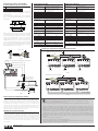
Collegamento elettrico e Rete RS485 /
Power and RS485 network connection:
1 Porta 485 / 485 Port
2 Antenna 2G/3G /2G/3G antenna
3 Alimentazione / Power supply
Seguire gli schemi indicati utilizzando cavo schermato
per reti RS485 /
Follow the diagrams shown, use
shielded cables:
Per il collegamento al pCO seguire i colori indicati in
fi gura /
To connect the pCO follow the colours indicated
in the fi gure:
3
2
1
Fig. 4
NON collegare le resistenze di terminazione da 120
sul primo e sull’ultimo dispositivo della rete in quanto
la porta Rs485 è di tipo HW slave, il numero massimo
di dispositivi collegabili nella rete è 10 e la lunghezza
massima della rete è 500m. /
DO NOT connect the
120
terminal resistors into the fi rst and the last
devices of the Rs485 network, this is because the Rs485
port is HW Slave type. The maximum number of devices
which can be connected in the network is
10
, and the
maximum lenght of it is 500 meters.
CAREL reserves the right to modify the features of its products without prior notice.
Schema per collegamento a pCO5 / Connection to pCO5
230 Vac
24 Vac
L
N
230 Vac
24 Vac
L
N
230 Vac
24 Vac
L
N
J26FBus2
J25 BMS2
J11 pLAN
pCO5
G
G0
J26FBus2
J25 BMS2
J11 pLAN
pCO5
G
G0
J26FBus2
J25 BMS2
J11 pLAN
pCO5
G
G0
collegare a terra /
connect to earth
Fig. 7
J26FBus2
J25 BMS2
J11 pLAN
pCO5
G
G0
J26FBus2
J25 BMS2
J11 pLAN
pCO5
G
G0
J26FBus2
J25 BMS2
J11 pLAN
pCO5
G
G0
Power supply
collegare a terra /
connect to earth
Fig. 8
GND
+
coppia intrecciata /
collegare a terra /
interfaced couple
G0/-
G/+
Fig. 5
RS485 shielded twisted pair cable
G
G0
G
G0
G
G0
or if no pCO
present
G
G0
12...30 Vdc
+
-
24 Vac
230 Vac
* Leggere le avvertenze
per il collegamento / Read
warnings for connection
To other device: max cable length 500m, max device 32
Fig. 6
Avvertenze per il collegamento elettrico
Utilizzare un trasformatore di sicurezza o un alimentatore con avvolgimenti
separati che assicuri un isolamento equivalente come stabilito nelle IEC
61558-2-6 e IEC 61558-2-17 e collegare la carcassa metallica del dispositivo e
la linea G0 a terra (collegamento funzionale). In caso di unico trasformatore
di alimentazione tra il dispositivo il relativo controllo, si raccomanda di non
invertire le connessioni G0 e G sui morsetti di alimentazione per evitare danni
ai dispositivi.Utilizzare un dispositivo di interruzione dell’alimentazione come
protezione in caso di guasto (per il dimensionamento vedere i dati nominali
riportati su “Ratings” nella tabella “Specifi che tecniche”).
Warnings for electrical connection
Use a safety transformer or power supply with separate windings that ensures
equivalent insulation as established by IEC 61558-2-6 and IEC 61558-2-17, and
earth the device’s metal casing and G0 line (functional connection). If the same
power transformer is used for the device and the corresponding controller,
do not reverse the G0 and G connections on the power terminals to avoid
damaging the devices.Use a power disconnect device as fault protection (to
size the device see the rated data shown under “Ratings” in the “Technical
specifi cations”).
This device complies with part 15 of the FCC Rules. Operation is subject to the following two conditions:
1. this device may not cause harmful interference, and
2. this device must accept any interference received, including interference that may cause undesired operation.
Changes or modifi cations not expressly approved by the party responsible for compliance could void the user’s
authority to operate the equipment. This equipment has been tested and found to comply with the limits for a Class B
digital device, pursuant to part 15 of the FCC Rules. These limits are designed to provide reasonable protection against
harmful interference in a residential installation. This equipment generates, uses and can radiate radio frequency
energy and, if not installed and used in accordance with the instructions, may cause harmful interference to radio
communications. However, there is no guarantee that interference will not occur in a particular installation. If this
equipment does cause harmful interference to radio or television reception, which can be determined by turning
the equipment off and on, the user is encouraged to try to correct the interference by one or more of the following
measures:
1: Reorient or relocate the receiving antenna.
2: Increase the separation between the equipment and receiver.
3: Connect the equipment into an outlet on a circuit diff erent from that to which the receiver is connected.4: Consult
the dealer or an experienced radio/TV technician for help.
-
 1
1
-
 2
2


Carel tERA Connect Box 2G/3G Assembly And Installation
- Tipo
- Assembly And Installation
in altre lingue
- English: Carel tERA Connect Box 2G/3G
Documenti correlati
-
Carel Tera Assembly And Installation
-
-
-
-
-
-
-
-
-