
DME
Installation and operating instructions
Montage- und Betriebsanleitung
Notice d’installation et d’entretien
Istruzioni di installazione e funzionamento
Instrucciones de instalación y funcionamiento
Instruções de instalação e funcionamento
√‰ËÁ›Â˜ ÂÁηٿÛÙ·Û˘ Î·È ÏÂÈÙÔùÚÁ›·˜
Installatie- en bedieningsinstructies
Monterings- och driftsinstruktion
Asennus- ja käyttöohjeet
Monterings- og driftsinstruktion
GRUNDFOS INSTRUCTIONS

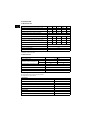
Declaration of Conformity
We GRUNDFOS declare under our sole responsibility that the prod-
ucts DME, to which this declaration relates, are in conformity with
the Council Directives on the approximation of the laws of the EEC
Member States relating to
– Machinery (98/37/EEC).
Standard used: EN 292.
– Electromagnetic compatibility (89/336/EEC).
Standards used: EN 61 000-6-2 and EN 61 000-6-3.
– Electrical equipment designed for use within certain voltage lim-
its (73/23/EEC).
Standards used: EN 60 335-1 and EN 60 335-2-41.
Konformitätserklärung
Wir GRUNDFOS erklären in alleiniger Verantwortung, daß die Pro-
dukte DME, auf die sich diese Erklärung bezieht, mit den folgenden
Richtlinien des Rates zur Angleichung der Rechtsvorschriften der
EG-Mitgliedstaaten übereinstimmen:
– Maschinen (98/37/EWG).
Norm, die verwendet wurde: EN 292.
– Elektromagnetische Verträglichkeit (89/336/EWG).
Normen, die verwendet wurden: EN 61 000-6-2 und
EN 61 000-6-3.
– Elektrische Betriebsmittel zur Verwendung innerhalb bestimmter
Spannungsgrenzen (73/23/EWG).
Normen, die verwendet wurden: EN 60 335-1 und
EN 60 335-2-41.
Déclaration de Conformité
Nous GRUNDFOS déclarons sous notre seule responsabilité que
les produits DME auxquels se réfère cette déclaration sont confor-
mes aux Directives du Conseil concernant le rapprochement des
législations des Etats membres CEE relatives à
– Machines (98/37/CEE).
Standard utilisé: EN 292.
– Compatibilité électromagnétique (89/336/CEE).
Standards utilisés: EN 61 000-6-2 et EN 61 000-6-3.
– Matériel électrique destiné à employer dans certaines limites de
tension (73/23/CEE).
Standards utilisés: EN 60 335-1 et EN 60 335-2-41.
Dichiarazione di Conformità
Noi GRUNDFOS dichiariamo sotto la nostra esclusiva responsabilità
che i prodotti DME ai quali questa dichiarazione se riferisce sono
conformi alle Direttive del Consiglio concernente il ravvicinamento
delle legislazioni degli Stati membri CEE relative a
– Macchine (98/37/CEE).
Standard usato: EN 292.
– Compatibilità elettromagnetica (89/336/CEE).
Standard usati: EN 61 000-6-2 e EN 61 000-6-3.
– Materiale elettrico destinato ad essere utilizzato entro certi limiti
di tensione (73/23/CEE).
Standard usati: EN 60 335-1 e EN 60 335-2-41.
Declaración de Conformidad
Nosotros GRUNDFOS declaramos bajo nuestra única responsabili-
dad que los productos DME a los cuales se refiere esta declaración
son conformes con las Directivas del Consejo relativas a la aproxi-
mación de las legislaciones de los Estados Miembros de la CEE
sobre
– Máquinas (98/37/CEE).
Norma aplicada: EN 292.
– Compatibilidad electromagnética (89/336/CEE).
Normas aplicadas: EN 61 000-6-2 y EN 61 000-6-3.
– Material eléctrico destinado a utilizarse con determinadas lími-
tes de tensión (73/23/CEE).
Normas aplicadas: EN 60 335-1 y EN 60 335-2-41.
Declaração de Conformidade
Nós GRUNDFOS declaramos sob nossa única responsabilidade
que os produtos DME aos quais se refere esta declaração estão em
conformidade com as Directivas do Conselho das Comunidades
Europeias relativas à aproximação das legislações dos Estados
Membros respeitantes à
– Máquinas (98/37/CEE).
Norma utilizada: EN 292.
– Compatibilidade electromagnética (89/336/CEE).
Normas utilizadas: EN 61 000-6-2 e EN 61 000-6-3.
– Material eléctrico destinado a ser utilizado dentro de certos limi-
tes de tensão (73/23/CEE).
Normas utilizadas: EN 60 335-1 e EN 60 335-2-41.
¢‹ÏˆÛË ™ùÌÌÞÚʈÛ˘
∂Ì›˜ Ë GRUNDFOS ‰ËÏÒÓÔùÌ Ì ·ðÔÎÏÂÈÛÙÈο ‰È΋ Ì·˜ Âùõ‡ÓË
ÞÙÈ Ù· ðÚÔÈÞÓÙ· DME ÛùÌÌÔÚÊÒÓÔÓÙ·È Ì ÙËÓ √‰ËÁ›· ÙÔù
™ùÌ‚ÔùÏ›Ôù Âð› Ù˘ Û‡ÁÎÏÈÛ˘ ÙˆÓ ÓÞÌˆÓ ÙˆÓ ∫Ú·ÙÒÓ MÂÏÒÓ Ù˘
∂ùÚˆð·È΋˜ ∂ÓˆÛ˘ Û ۯ¤ÛË Ì ٷ
– ªË¯·Ó‹Ì·Ù· (98/37/EEC).
¶ÚÞÙùðÔ ðÔù ¯ÚËÛÈÌÔðÔÈ‹õËÎÂ: EN 292.
– ∏ÏÂÎÙÚÔÌ·ÁÓËÙÈ΋ ÛùÌ‚·ÙÞÙËÙ· (89/336/EEC).
¶ÚÞÙùð· ðÔù ¯ÚËÛÈÌÔðÔÈ‹õËηÓ: EN 61 000-6-2 ηÈ
EN 61 000-6-3.
– ∏ÏÂÎÙÚÈΤ˜ ÛùÛÎÂù¤˜ ۯ‰ȷṲ̂Ó˜ ÁÈ¿ ¯Ú‹ÛË ÂÓÙÞ˜
ÔÚÈÛÌ¤ÓˆÓ ÔÚ›ˆÓ ËÏÂÎÙÚÈ΋˜ Ù¿Û˘ (73/23/EEC).
¶ÚÞÙùð· ðÔù ¯ÚËÛÈÌÔðÔÈ‹õËηÓ: EN 60 335-1 ηÈ
EN 60 335-2-41.
Overeenkomstigheidsverklaring
Wij GRUNDFOS verklaren geheel onder eigen verantwoordelijkheid
dat de produkten DME waarop deze verklaring betrekking heeft in
overeenstemming zijn met de Richtlijnen van de Raad inzake de
onderlinge aanpassing van de wetgevingen van de Lid-Staten
betreffende
– Machines (98/37/EEG).
Norm: EN 292.
– Elektromagnetische compatibiliteit (89/336/EEG).
Normen: EN 61 000-6-2 en EN 61 000-6-3.
– Elektrisch materiaal bestemd voor gebruik binnen bepaalde
spanningsgrenzen (73/23/EEG).
Normen: EN 60 335-1 en EN 60 335-2-41.
Försäkran om överensstämmelse
Vi GRUNDFOS försäkrar under ansvar, att produkterna DME, som
omfattas av denna försäkran, är i överensstämmelse med Rådets
Direktiv om inbördes närmande till EU-medlemsstaternas lagstift-
ning, avseende
– Maskinell utrustning (98/37/EC).
Använd standard: EN 292.
– Elektromagnetisk kompatibilitet (89/336/EC).
Använda standarder: EN 61 000-6-2 och EN 61 000-6-3.
– Elektrisk material avsedd för användning inom vissa spännings-
gränser (73/23/EC).
Använda standarder: EN 60 335-1 och EN 60 335-2-41.
Vastaavuusvakuutus
Me GRUNDFOS vakuutamme yksin vastuullisesti, että tuotteet
DME, jota tämä vakuutus koskee, noudattavat direktiivejä jotka
käsittelevät EY:n jäsenvaltioiden koneellisia laitteita koskevien
lakien yhdenmukaisuutta seur.:
– Koneet (98/37/EY).
Käytetty standardi: EN 292.
– Elektromagneettinen vastaavuus (89/336/EY).
Käytetyt standardit: EN 61 000-6-2 ja EN 61 000-6-3.
– Määrättyjen jänniterajoitusten puitteissa käytettävät sähköiset
laitteet (73/23/EY).
Käytetyt standardit: EN 60 335-1 ja EN 60 335-2-41.
Overensstemmelseserklæring
Vi GRUNDFOS erklærer under ansvar, at produkterne DME, som
denne erklæring omhandler, er i overensstemmelse med Rådets
direktiver om indbyrdes tilnærmelse til EF medlemsstaternes lovgiv-
ning om
– Maskiner (98/37/EØF).
Anvendt standard: EN 292.
– Elektromagnetisk kompatibilitet (89/336/EØF).
Anvendte standarder: EN 61 000-6-2 og EN 61 000-6-3.
– Elektrisk materiel bestemt til anvendelse inden for visse
spændingsgrænser (73/23/EØF).
Anvendte standarder: EN 60 335-1 og EN 60 335-2-41.
Bjerringbro, 1st January 2002
Jan Strandgaard
Technical Manager

4
CONTENTS
Page
1. General description 4
1.1 Applications 4
1.2 Type key 5
2. Technical data 6
2.1 Mechanical data 6
2.2 Electrical data 6
2.3 Input/output data 6
2.4 Dimensions 7
3. Installation 7
3.1 Safety instructions 7
3.2 Installation environment 7
3.3 Installation of pump 7
3.4 Installation example 8
3.5 Electrical connection 8
3.6 Connection overview 9
4. Functions 10
4.1 Control panel 10
4.2 Start/stop of pump 11
4.3 Priming/venting of pump 11
4.4 Level control 11
4.5 Indicator lights and alarm output 11
4.6 Fieldbus communication 12
4.7 Menu 13
4.8 Operating modes 14
4.9 Manual 14
4.10 Pulse 14
4.11 Analog 14
4.12 Timer 16
4.13 Batch 17
4.14 Anti-cavitation 17
4.15 Capacity limitation 18
4.16 Counters 18
4.17 Resetting 19
4.18 Return 19
4.19 Language 19
4.20 Input setup 20
4.21 Measuring units 21
4.22 Dosing monitoring 22
4.23 Control panel lock 23
5. Start-up 24
6. Calibration 25
6.1 Direct calibration 26
6.2 Indirect calibration 27
6.3 Check calibration 28
7. Maintenance 28
8. Service 28
9. Fault finding chart 29
10. Disposal 29
Before beginning installation procedures,
these installation and operating instruc-
tions should be studied carefully. The in-
stallation and operation should also be in
accordance with local regulations and ac-
cepted codes of good practice.
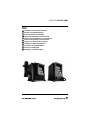
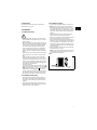
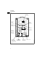
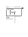
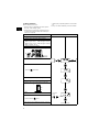
1. General description
The GRUNDFOS DME dosing pump is a self-priming
diaphragm pump.
The pump consists of:
•a cabinet incorporating the drive unit and elec-
tronics,
•a dosing head with back plate, diaphragm,
valves, connections and vent valve and
•a control panel incorporating display and buttons.
The control panel can be fitted either to the end or
to the side of the cabinet.
Being equipped with a stepper motor, this dosing
pump is unique in its field. The stepper motor offers
the possibility of varying the capacity by changing
the duration of the dosing stroke.
Furthermore, the motor is controlled in such a way
that the dosing gets as even and constant as possi-
ble, irrespective of the capacity range in which the
pump is operating.
This is carried out as follows:
The speed of the suction stroke is kept constant and
the stroke relatively short, irrespective of the capa-
city. Contrary to conventional pumps, which generate
the dosing stroke as a short pulse, the duration of
the dosing stroke will be as long as possible. Thus,
an even dosing without peak values is ensured. As
the pump is always dosing at full stroke length, it en-
sures the same high accuracy and suction capability,
irrespective of the capacity, which is infinitely varia-
ble in the ratio of 1:1000.
The pump features an LCD display and a user-
friendly control panel which gives access to the
pump functions.
1.1 Applications
The DME dosing pump is designed for handling
chemicals within the following ranges of applications,
among others:
• Drinking water treatment.
• Wastewater treatment.
• Swimming pool water treatment.
• Boiler water treatment.
• Cooling water treatment.
• Process water treatment.
• Washing systems.

5
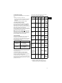
1.2 Type key
(Cannot be used for pump configuration.)
Example
:
Pump range DME ..
Control variant Code
Standard A
Standard + alarm relay AR
Standard + Profibus AP
Standard + GENIbus AG
Dosing head material Code
Polypropylene PP
PVDF PV
Stainless steel 1.4401 SS
Code Mains plug
F EU (Schuko)
B USA, CAN
GUK
IAU
ECH
JJP
Code
Connection,
suction/discharge
1 Tubing 6/9
Tubing 4/6
supplied with the pump
2 Tubing 6/9
Tubing 6/12+9/12
supplied with the pump
3 Tubing 4/6
4 Tubing 6/9
5 Tubing 6/12
6 Tubing 9/12
A Threaded Rp 1/4
B Threaded Rp 3/8
E Cementing d.10
F Cementing d.12
Code Valves
1 Standard valve
2 Spring-loaded valve
Valve ball material Code
Ceramics C
Stainless steel 1.4401 SS
Gasket material Code
EPDM E
FKM V
PTFE T
Maximum pressure [bar]
Control panel Code
Front-fitted F
Side-fitted S
Voltage Code
1 x 100-240 V, 50-60 Hz 3
DME 2-18 A-PP/E/C-F-3 1 1E F

6
2. Technical data
2.1 Mechanical data
*
1
Irrespective of counter pressure
*
2
Maximum suction lift 1 metre
2.2 Electrical data
2.3 Input/output data
The pump offers various input and output possibili-
ties, depending on control variant.
DME 2 DME 8 DME 12 DME 19 DME 48
Maximum capacity without anti-cavitation *
1
[l/h] 2.5 7.5 12 18.5 48
Maximum capacity with anti-cavitation *
1
[l/h] 1.8 5.6 9 14.5 37
Maximum pressure [bar] 18 10 6 6.2 2.6
Maximum stroke rate per minute [stroke/min.] 180 180 180 151 151
Maximum suction lift during operation [m] 6
Maximum suction lift when priming with wet valves [m] 1.8 3 3 3 3
Maximum viscosity with spring-loaded valves *
2
[mPas] 500 500 500 500 100
Maximum viscosity without spring-loaded valves *
2
[mPas]
200 200 200 200 100
Diaphragm diameter [mm] 28 38 42.5 55 77
Liquid temperature [°C] 0 to 50
Ambient temperature [°C] 0 to 45
Accuracy of repeatability ±1%
Sound pressure level [dB(A)] <70
DME 2, 8, 12 DME 19, 48
Supply voltage [VAC] 1 x 100-240
Maximum current consumption [A]
at 100 V 0.30 0.36
at 230 V 0.16 0.26
Maximum power consumption P
1
[W] 18 22
Frequency [Hz] 50-60
Enclosure class IP 65
Insulation class B
Supply cable 1.5 m H05RN-F with plug
Signal input
Voltage in level sensor input [VDC] 5
Voltage in pulse input [VDC] 5
Minimum pulse-repetition period [ms] 3.3
Impedance in analog 4-20 mA input [Ω]250
Maximum loop resistance in pulse signal circuit [Ω]350
Maximum loop resistance in level signal circuit [Ω]350
Signal output
Maximum load of alarm relay output, at ohmic load [A] 2
Maximum voltage, alarm relay output [V] 250

7
2.4 Dimensions
See dimensions at the end of these instructions.
All dimensions are in mm.
3. Installation
3.1 Safety instructions
• When working with chemicals, local safety rules
and regulations must be observed (e.g. wear pro-
tective clothes).
• Before starting work on the dosing pump and sys-
tem, disconnect the electricity supply to the pump,
ensuring that it cannot be accidentally switched
on. Before reconnecting the electricity supply,
make sure that the dosing hose is positioned in
such a way that any chemical left in the dosing
head is not ejected, thereby exposing persons to
danger.
• If the vent valve in the dosing head is used, it must
be connected to a hose which is led back to the
tank.
• When changing a chemical, make sure that the
materials of the dosing pump and system are re-
sistant to the new chemical. If there is any risk of
chemical reaction between the two types of chem-
icals, clean the pump and system thoroughly be-
fore adding the new chemical.
Proceed as follows:
Place the suction tube in water and press the
button until residual chemical has been removed.
Note: When the buttons and are pressed
simultaneously, the pump can be set to run for a
specific number of seconds at maximum capacity.
The remaining number of seconds will appear in
the display. The maximum value is 300 seconds.
3.2 Installation environment
• Exposure to direct sunlight should be avoided.
This applies especially to pumps with plastic dos-
ing heads, as this material can be damaged by
sunlight.
• If the pump is installed outside, an enclosure or
similar protection is required to protect the pump
against rain and similar weathers.
3.3 Installation of pump
• See also the installation example in section
3.4
.
• Note: The dosing head may contain water from
the factory test. If a liquid which must not come
into contact with water is to be dosed, it is recom-
mended to let the pump run with another liquid to
remove the water from the dosing head before in-
stallation.
• Always install the pump on the supporting foot
with vertical suction and discharge ports.
• Always use suitable tools for the mounting of plas-
tic parts. Never apply unnecessary force.
• Make sure that the dosing pump and system are
designed in such a way that neither system equip-
ment nor buildings are damaged in case of leak-
age from the pump or rupture of hoses/pipes. The
installation of leakage hoses and collecting tanks
is recommended.
• Make sure that the drain hole in the dosing head
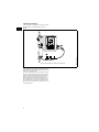
points downwards, see fig. 1.
Note: It is important that the drain pipe/hole is not
inserted direct into the tank contents, as gasses
may penetrate into the pump.
Fig. 1
100%
100%
TM01 8420 5099
hole
Drain

8
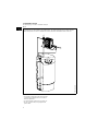
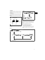
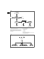
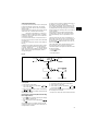
3.4 Installation example
The drawing in fig. 2 shows an installation example.
Fig. 2
3.5 Electrical connection
• The electrical connection of the pump should be
carried out by qualified persons in accordance
with local regulations.
• For electrical data of the pump, see section
2.2
.
• Do not lay signal cables, if any, together with
power cables.
TM01 8421 1600
The DME pump can be installed in many different ways. The sketch below shows an example with side-
fitted control panel. The tank is a GRUNDFOS chemical tank with a GRUNDFOS level control unit.

9
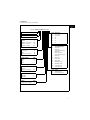
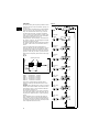
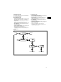
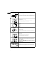
3.6 Connection overview
Fig. 3
Control input:
1 = Contact for pulse signal
2 = Contact for external on/off
Level input:
TM01 8422 0603
2
3
1
4
1
3
4
5
1
3
4
5
3
1
4
2
2
Alarm relay (control variant “AR” only)
Control cable,
see table below
Level cable,
see table below
“NO” black
“NC” blue
“Com” brown
Empty tank
Low level
Number / colour 1 / brown 2 / white 3 / blue 4 / black 5 / grey Description
Function
Manual 2 2
Pulse 1 1
Pulse + external on/off 1 1 + 2 2
Analog – + mA signal
Analog + external on/off 2 2 – + mA signal
Timer + external on/off 2 2
Batch 1 1
Number / colour 1 / brown 2 / white 3 / blue 4 / black
Function
Low level Low level
Empty tank Empty tank
Low level Empty tank Low level + empty tank
Dosing monitoring Dosing monitoring

10
4. Functions
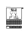
4.1 Control panel
Fig. 4
TM01 8423 0100
ml/h
100%
LCD display,
see section
4.7
Navigation/
settings,
see section
4.7
Menu,
see section
4.7
On/off button,
see section
4.7
Mains connectionM12 connection
level control,
see section
4.4
M12 connection
pulse/analog input,
see section
4.4
Connection
alarm relay/bus.
Control variants
“AR”, “AP” and “AG”,
see sections
4.5
and
4.6
Red
indicator light,
see section
4.5
Green
indicator light,
see section
4.5
Maximum capacity
(priming),
see section
4.3
Navigation/
settings,
see section
4.7

11
4.2 Start/stop of pump
The pump can be started/stopped in three different
ways:
• Locally on the pump control panel.
• By means of an external on/off switch connected
to the pulse input. See connection overview in
section
3.6
.
• By switching on/off the electricity supply.
4.3 Priming/venting of pump
The pump control panel incorporates a button.
Press this button if the maximum pump capacity is
required over a short period, e.g. during start-up.
When the button is released, the pump automatically
returns to the previous operating mode.
During priming/venting, it is recommended to let the
pump run without a counter pressure or to loosen the
vent valve by giving it a 1/8 to 1/4 turn.
Note: When the buttons and are pressed si-
multaneously, the pump can be set to run for a spe-
cific number of seconds at maximum capacity. The
remaining number of seconds will appear in the dis-
play. The maximum value is 300 seconds.
4.4 Level control
The pump can be fitted with a level control unit for
monitoring of the chemical level in the tank.
The pump can react to two level signals. The pump
will react differently, depending on the influence on
the individual level sensors.
* Control variant “AR” only.
See section
3.6
for connection of the level control
unit and alarm output.
4.5 Indicator lights and alarm output
The green and red indicator lights on the pump are
used for operating and fault indication.
In control variant “AR”, the pump can activate an ex-
ternal alarm signal by means of a built-in alarm relay.
The alarm signal is activated by means of an internal
potential-free contact.
The functions of the indicator lights and the built-in
alarm relay appear from the table below:
!1
Control variant AR only.
!2
Requires connection to level sensors.
!3
Requires activation of the dosing monitoring
function and connection to a dosing monitor.
Level sensors Pump reaction
Upper sensor
activated
(closed contact)
• Red indicator light is on.
• Pump running.
• Alarm relay activated.*
Lower sensor
activated
(closed contact)
• Red indicator light is on.
• Pump stopped.
• Alarm relay activated.*
100%
100%
Condition
Green
LED
Red
LED
Dis-
play
Alarm
output
!1
Pump
running
On Off
Normal
indication
Set to stop
Flash-
ing
Off
Normal
indication
Pump fault Off On EEPROM
Supply
failure
Off Off Off
Pump run-
ning, low
chemical
level
!2
On On
Normal
indication
Empty
tank
!2
Off On
Normal
indication
Analog
signal
< 2 mA
Off On
Normal
indication
The dosed
quantity is
too small
according
to the sig-
nal from the
dosing
monitor
!3
On On
Normal
indication
Overheat-
ing
Off On
MAX.
TEMP.
132
NC NO C
132
NC NO C
1
23
NC NO C
132
NC NO C
1
23
NC NO C
1
23
NC NO C
1
23
NC NO C
1
23
NC NO C
1
23
NC NO C

12
4.6 Fieldbus communication
The pump can be configured for fieldbus applica-
tions.
The following bus types are available:
Separate instructions are supplied with each bus
type.
Control variant Bus type
AP Profibus
AG GENIbus

13
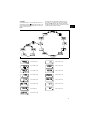
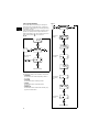
4.7 Menu
The pump features a user-friendly menu which is ac-
tivated by pressing the button. During start-up, all
texts will appear in English language. To select lan-
guage, see section
4.19
.
All menu items are described in the following sec-
tions. When appears at a menu item, it means
that this item is activated. By selecting “RETURN”
anywhere in the menu structure, you will return to the
operating display without changes.
Fig. 5
See section
4.9
See section
4.23
See section
4.10
See section
4.17
See section
4.11
See section
4.18
See section
4.12
See section
4.19
See section
4.13
See section
4.15
See section
4.14
See section
4.20
See section
6
See section
4.21
See section
4.16

14
4.8 Operating modes
Note: The displayed l and ml values are only reliable
if the pump has been calibrated to the actual installa-
tion, see section
6
.
The pump can run in five different operating modes:
•Manual
•Pulse
•Analog
•Timer (internal batch control)
• Batch (external batch control)
See description in the following sections.
4.9 Manual
The pump is dosing as constantly and evenly as pos-
sible, without any external signals.
Set the quantity to be dosed in l/h or ml/h. The pump
automatically changes over between the measuring
units.
Setting range:
DME 2: 2.5 ml/h - 2.5 (1.8*) l/h
DME 8: 7.5 ml/h - 7.5 (5.6*) l/h
DME 12: 12 ml/h - 12 (9*) l/h
DME 19: 18.5 ml/h - 18.5 (14.5*) l/h
DME 48: 48 ml/h - 48 (37*) l/h
* The figures in brackets indicate the maximum ca-
pacity when the anti-cavitation function is acti-
vated.
Fig. 6
4.10 Pulse
The pump is dosing according to an external pulse
signal, i.e. a water meter with pulse output or a con-
troller.
Set the quantity to be dosed per pulse in ml/pulse.
The pump adjusts its capacity according to two fac-
tors:
• Frequency of external pulses.
• The set quantity per pulse.
Setting range:
DME 2: 0.000018 ml/pulse - 5 ml/pulse
DME 8: 0.000069 ml/pulse - 15 ml/pulse
DME 12: 0.000111 ml/pulse - 24 ml/pulse
DME 19: 0.000204 ml/pulse - 37 ml/pulse
DME 48: 0.00530 ml/pulse - 96 ml/pulse
Fig. 7
If the set quantity per pulse multiplied by the pulse
frequency exceeds the pump capacity, the pump will
run at maximum capacity. Excess pulses will be ig-
nored and the “actual capacity” display will flash.
4.11 Analog
The pump is dosing according to an external analog
signal. The dosed quantity is proportional to the input
value in mA.
4-20 (default): 4 mA = 0%.
20 mA = 100%.
20-4: 4 mA = 100%.
20 mA = 0%.
0-20: 0 mA = 0%.
20 mA = 100%.
20-0: 0 mA = 100%.
20 mA = 0%.
See fig. 8.
The capacity limitation will influence the capacity.
100% corresponds to the maximum capacity of the
pump or the set maximum capacity, see section
4.15
.
Fig. 8
Set value
TM02 4498 1102
Set quantity in
ml/pulse
Actual capacity
in ml/h or l/h
0 4 8 12 16 20
0
20
40
60
80
100
4-20 mA
0-20 mA
[mA]
[%]

15
Fig. 9
If 4-20 mA or 20-4 mA is selected and the signal falls
below 2 mA, the pump will indicate a fault. This situa-
tion occurs if the connection is interrupted, for in-
stance if the wire is damaged.
Change the analog mode as illustrated in fig. 10:
Fig. 10
Value
according to
analog signal
Use the buttons
for navigation

16
4.12 Timer
The pump is dosing the set quantity in batches at the
maximum capacity or the set maximum capacity, see
section
4.15
.
The time until the first dosing “NX” and the following
sequences “IN” can be set in minutes, hours and
days. The maximum time limit is 9 days, 23 hours
and 59 minutes (9:23:59). The lowest acceptable
value is 1 minute.
The internal timer continues even
if the pump is stopped by means of the on/off button,
empty tank or stop signal, see fig. 11.
During operation, “NX” will always count down from
“IN” to zero. In this way, the remaining time until the
next batch can always be read.
“IN” must be higher than the time required to perform
one batch. If “IN” is lower, the next batch will be ig-
nored.
In case of supply failure, the set quantity to be
dosed, the “IN” time and the remaining “NX” time are
stored. When the supply is reconnected, the pump
will start up with the “NX” time at the time of the sup-
ply failure. In this way, the timer cycle will continue,
but it has been delayed by the duration of the supply
failure.
Fig. 11
Setting range:
DME 2: 0.23 ml/batch - 5 l/batch
DME 8: 0.69 ml/batch - 15 l/batch
DME 12: 1.11 ml/batch - 24 l/batch
DME 19: 2.04 ml/batch - 37 l/batch
DME 48: 5.3 ml/batch - 96 l/batch
Only values corresponding to complete dosing
strokes (according to the calibration factor) can be
selected.
Example: If the calibration factor is 23.3 (= 0.233 ml/
stroke), the minimum settable value in timer or batch
mode will be 0.233 ml -> the next will be 0.466 ml ->
the next will be 0.699 ml, etc.
These steps will continue up to a value correspond-
ing to 100 dosing strokes. Above this value, the set-
ting range has standard steps as in other operating
modes.
If the calibration factor is changed after setting of
timer or batch mode, the pump will automatically re-
calculate a new amount of dosing strokes per batch
and change the display value to the nearest possible
value compared to the first one set.
Fig. 12
TM01 8942 0900
NX
IN
Quantity per batch
Set quantity
per batch
Set IN value
in minutes
Set IN value
in hours
Set IN value
in days
Set NX value
in hours
Set NX value
in minutes
Set NX value
in days

17
4.13 Batch
The pump is dosing the set quantity in batches at the
maximum capacity or the set maximum capacity, see
section
4.15
.
The quantity is dosed every time the pump receives
an external pulse.
If the pump receives new pulses before the previous
batch is performed, these pulses will be ignored.
Fig. 13
The setting range is the same as for Timer, see sec-
tion
4.12
.
Fig. 14
4.14 Anti-cavitation
The pump features an anti-cavitation function. When
this function is selected, the pump extends and
smooths its suction stroke, resulting in softer prim-
ing.
The anti-cavitation function is used:
• when pumping liquids of high viscosity,
• in the case of a long suction tube and
• in the case of a high suction lift.
The maximum pump capacity is reduced when this
function is selected. See section
2.1 Mechanical
data
.
Fig. 15
TM01 8947 0900
Pulse Pulse
Quantity per batch
Set value
per batch
Operating display

18
4.15 Capacity limitation
This function offers the possibility of reducing the
maximum pump capacity (MAX CAP). It influences
the functions in which the pump is normally operating
at maximum capacity.
Under normal operating conditions, the pump cannot
operate at a capacity which is higher than the one
stated in the display. This does not apply to the max-
imum capacity button , see section
4.3
.
Fig. 16
4.16 Counters
The pump can display “non-resettable” counters for:
•“QUANTITY”
Accumulated value of dosed quantity in litres or
US gallons.
•“STROKES”
Accumulated number of dosing strokes.
•“HOURS”
Accumulated number of operating hours
(Power on).
•“POWER ON”
Accumulated number of times the electricity sup-
ply has been switched on.
Fig. 17
100%
Set maximum
capacity
Operating display
Operating display
Total number
of strokes
Total number
of operating
hours
Total number
of starts
Total dosed
quantity

19
4.17 Resetting
When “DEFAULT” is activated, the pump will return
to the factory settings.
Note: The calibration is also set back to the default
setting. This means that a new calibration is required
when the “DEFAULT” function has been used.
Fig. 18
4.18 Return
Fig. 19
The “RETURN” function makes it possible to return
from any level in the menu to the operating display
without changes after the menu functions have been
used.
4.19 Language
The display text can be displayed in one of the fol-
lowing languages:
•English
•German
•French
• Italian
• Spanish
• Portuguese
•Dutch
•Swedish
•Finnish
•Danish
•Czech
• Slovak
• Polish
• Russian
Operating display Operating display
without changes

20
Fig. 20
4.20 Input setup
Fig. 21 shows all possible settings.
The level and stop inputs can be changed from NO
(normally open) to NC (normally closed) function. If
changed, the inputs must be short-circuited in nor-
mal operation.
For the analog input, one of the following signal
types can be selected:
• 4-20 mA (default),
• 20-4 mA,
• 0-20 mA,
• 20-0 mA.
See also section
4.11 Analog
.
Change the level input to an input for dosing monitor-
ing as illustrated in fig. 21.
Fig. 21
Operating display Operating display Operating display
without changes
Use the buttons
for navigation

21
4.21 Measuring units
It is possible to select metric units (litre/millilitre) or
US units (gallons/millilitre).
Metric measuring units:
• In manual and analog modes, set the quantity to
be dosed in litres per hour (l/h) or millilitres per
hour (ml/h).
• In pulse mode, set the quantity to be dosed in
ml/pulse. The actual capacity is indicated in litres
per hour (l/h) or millilitres per hour (ml/h).
• For calibration, set the quantity to be dosed in
ml per 100 strokes.
• In timer and batch modes, set the quantity to be
dosed in litres (l) or millilitres (ml).
• Under the “QUANTITY” menu item in the
“COUNTERS” menu, the dosed quantity is indi-
cated in litres.
US measuring units:
• In manual and analog modes, set the quantity to
be dosed in gallons per hour (gph).
• In pulse mode, set the quantity to be dosed in
ml/pulse. The actual capacity is indicated in
gallons per hour (gph).
• For calibration, set the quantity to be dosed in
ml per 100 strokes.
• In timer and batch modes, set the quantity to be
dosed in gallons (gal).
• Under the “QUANTITY” menu item in the
“COUNTERS” menu, the dosed quantity is indi-
cated in US gallons (gal).
Fig. 22
Operating display Operating display
3 x
La pagina si sta caricando...
La pagina si sta caricando...
La pagina si sta caricando...
La pagina si sta caricando...
La pagina si sta caricando...
La pagina si sta caricando...
La pagina si sta caricando...
La pagina si sta caricando...
-
 1
1
-
 2
2
-
 3
3
-
 4
4
-
 5
5
-
 6
6
-
 7
7
-
 8
8
-
 9
9
-
 10
10
-
 11
11
-
 12
12
-
 13
13
-
 14
14
-
 15
15
-
 16
16
-
 17
17
-
 18
18
-
 19
19
-
 20
20
-
 21
21
-
 22
22
-
 23
23
-
 24
24
-
 25
25
-
 26
26
-
 27
27
-
 28
28


Grundfos DME 2 series Installation And Operating Instructions Manual
- Tipo
- Installation And Operating Instructions Manual
- Questo manuale è adatto anche per
in altre lingue
- English: Grundfos DME 2 series
Documenti correlati
-
Grundfos DME 48 Installation And Operating Instructions Manual
-
Grundfos DME 375 Installation And Operating Instructions Manual
-
Grundfos DMM 23 Installation And Operating Instructions Manual
-
-
Grundfos 96 00 53 77 Installation And Operating Instructions Manual
-
-
-
Grundfos DMS 2 Installation And Operating Instructions Manual
-
Grundfos CU 401 Installation And Operating Instructions Manual
-
Altri documenti
-
ProMinent GMXa Operating Instructions Manual
-
-
-
-
-