ONKYO TX-NR727 Manuale del proprietario
- Categoria
- Ricevitori AV
- Tipo
- Manuale del proprietario

E
n
AV RECEIVER
TX-NR727
Instruction Manual
Contents
Safety Information and Introduction ............2
Table of Contents...........................................6
Connections .................................................12
Turning On & Basic Operations..................21
Playback........................................................29
Advanced Operations ..................................52
Controlling Other Components...................76
Appendix.......................................................82
Internet Radio Guide
Remote Control Codes

En-2
Safety Information and Introduction
Important Safety Instructions
1. Read these instructions.
2. Keep these instructions.
3. Heed all warnings.
4. Follow all instructions.
5. Do not use this apparatus near water.
6. Clean only with dry cloth.
7. Do not block any ventilation openings. Install in
accordance with the manufacturer’s instructions.
8. Do not install near any heat sources such as
radiators, heat registers, stoves, or other
apparatus (including amplifiers) that produce
heat.
9. Do not defeat the safety purpose of the polarized
or grounding-type plug. A polarized plug has two
blades with one wider than the other. A grounding
type plug has two blades and a third grounding
prong. The wide blade or the third prong are
provided for your safety. If the provided plug does
not fit into your outlet, consult an electrician for
replacement of the obsolete outlet.
10. Protect the power cord from being walked on or
pinched particularly at plugs, convenience
receptacles, and the point where they exit from
the apparatus.
11. Only use attachments/accessories specified by
the manufacturer.
12. Use only with the cart,
stand, tripod, bracket, or
table specified by the
manufacturer, or sold with
the apparatus. When a cart
is used, use caution when
moving the cart/apparatus
combination to avoid injury
from tip-over.
13. Unplug this apparatus during lightning storms or
when unused for long periods of time.
14. Refer all servicing to qualified service personnel.
Servicing is required when the apparatus has
been damaged in any way, such as power-supply
cord or plug is damaged, liquid has been spilled or
objects have fallen into the apparatus, the
apparatus has been exposed to rain or moisture,
does not operate normally, or has been dropped.
15. Damage Requiring Service
Unplug the apparatus from the wall outlet and
refer servicing to qualified service personnel
under the following conditions:
A. When the power-supply cord or plug is
damaged,
B. If liquid has been spilled, or objects have fallen
into the apparatus,
C. If the apparatus has been exposed to rain or
water,
D. If the apparatus does not operate normally by
following the operating instructions. Adjust
only those controls that are covered by the
operating instructions as an improper
adjustment of other controls may result in
damage and will often require extensive work
by a qualified technician to restore the
apparatus to its normal operation,
E. If the apparatus has been dropped or
damaged in any way, and
F. When the apparatus exhibits a distinct change
in performance this indicates a need for
service.
16. Object and Liquid Entry
Never push objects of any kind into the apparatus
through openings as they may touch dangerous
voltage points or short-out parts that could result
in a fire or electric shock.
The apparatus shall not be exposed to dripping or
splashing and no objects filled with liquids, such
as vases shall be placed on the apparatus.
Don’t put candles or other burning objects on top
of this unit.
17. Batteries
Always consider the environmental issues and
follow local regulations when disposing of
batteries.
18. If you install the apparatus in a built-in installation,
such as a bookcase or rack, ensure that there is
adequate ventilation.
Leave 20 cm (8") of free space at the top and
sides and 10 cm (4") at the rear. The rear edge of
the shelf or board above the apparatus shall be
set 10 cm (4") away from the rear panel or wall,
creating a flue-like gap for warm air to escape.
WARNING:
TO REDUCE THE RISK OF FIRE OR ELECTRIC
SHOCK, DO NOT EXPOSE THIS APPARATUS TO RAIN
OR MOISTURE.
CAUTION:
TO REDUCE THE RISK OF ELECTRIC SHOCK, DO NOT
REMOVE COVER (OR BACK). NO USER-SERVICEABLE
PARTS INSIDE. REFER SERVICING TO QUALIFIED
SERVICE PERSONNEL.
The lightning flash with arrowhead symbol, within
an equilateral triangle, is intended to alert the
user to the presence of uninsulated “dangerous
voltage” within the product’s enclosure that may
be of sufficient magnitude to constitute a risk of
electric shock to persons.
The exclamation point within an equilateral
triangle is intended to alert the user to the
presence of important operating and
maintenance (servicing) instructions in the
literature accompanying the appliance.
WARNING
RISK OF ELECTRIC SHOCK
DO NOT OPEN
RISQUE DE CHOC ELECTRIQUE
NE PAS OUVRIR
A VIS
PORTABLE CART WARNIN
G
S3125A

Safety Information and Introduction
En-3
Precautions
1. Recording Copyright—Unless it’s for personal
use only, recording copyrighted material is illegal
without the permission of the copyright holder.
2. AC Fuse—The AC fuse inside the unit is not user-
serviceable. If you cannot turn on the unit, contact
your Onkyo dealer.
3. Care—Occasionally you should dust the unit all
over with a soft cloth. For stubborn stains, use a
soft cloth dampened with a weak solution of mild
detergent and water. Dry the unit immediately
afterwards with a clean cloth. Don’t use abrasive
cloths, thinners, alcohol, or other chemical
solvents, because they may damage the finish or
remove the panel lettering.
4. Power
WARNING
BEFORE PLUGGING IN THE UNIT FOR THE
FIRST TIME, READ THE FOLLOWING SECTION
CAREFULLY.
AC outlet voltages vary from country to country.
Make sure that the voltage in your area meets the
voltage requirements printed on the unit’s rear
panel (e.g., AC 230 V, 50 Hz or AC 120 V, 60 Hz).
The power cord plug is used to disconnect this
unit from the AC power source. Make sure that
the plug is readily operable (easily accessible) at
all times.
For models with [POWER] button, or with both
[POWER] and [ON/STANDBY] buttons:
Pressing the [POWER] button to select OFF
mode does not fully disconnect from the mains. If
you do not intend to use the unit for an extended
period, remove the power cord from the AC outlet.
For models with [ON/STANDBY] button only:
Pressing the [ON/STANDBY] button to select
Standby mode does not fully disconnect from the
mains. If you do not intend to use the unit for an
extended period, remove the power cord from the
AC outlet.
5. Preventing Hearing Loss
Caution
Excessive sound pressure from earphones and
headphones can cause hearing loss.
6. Batteries and Heat Exposure
Warning
Batteries (battery pack or batteries installed) shall
not be exposed to excessive heat as sunshine,
fire or the like.
7. Never Touch this Unit with Wet Hands—Never
handle this unit or its power cord while your hands
are wet or damp. If water or any other liquid gets
inside this unit, have it checked by your Onkyo
dealer.
8. Handling Notes
• If you need to transport this unit, use the original
packaging to pack it how it was when you
originally bought it.
• Do not leave rubber or plastic items on this unit
for a long time, because they may leave marks
on the case.
• This unit’s top and rear panels may get warm
after prolonged use. This is normal.
• If you do not use this unit for a long time, it may
not work properly the next time you turn it on, so
be sure to use it occasionally.
For U.S. and Canadian models
FCC CAUTION
Changes or modifications not expressly approved by
the party responsible for compliance could void the
user’s authority to operate the equipment.
Note:
This equipment has been tested and found to comply
with the limits for a Class B digital device, pursuant to
part 15 of the FCC Rules. These limits are designed
to provide reasonable protection against harmful
interference in a residential installation. This
equipment generates, uses and can radiate radio
frequency energy and, if not installed and used in
accordance with the instructions, may cause harmful
interference to radio communications. However, there
is no guarantee that interference will not occur in a
particular installation. If this equipment does cause
harmful interference to radio or television reception,
which can be determined by turning the equipment off
and on, the user is encouraged to try to correct the
interference by one or more of the following
measures:
–Reorient or relocate the receiving antenna.
–Increase the separation between the equipment
and receiver.
–Connect the equipment into an outlet on a circuit
different from that to which the receiver is
connected.
–Consult the dealer or an experienced radio/TV
technician for help.
This device complies with Industry Canada licence-
exempt RSS standard(s). Operation is subject to the
following two conditions: (1) this device may not
cause interference, and (2) this device must accept
any interference, including interference that may
cause undesired operation of the device.
Le présent appareil est conforme aux CNR d’Industrie
Canada applicables aux appareils radio exempts de
licence. L’exploitation est autorisée aux deux
conditions suivantes : (1) l’appareil ne doit pas
produire de brouillage, et (2) l’utilisateur de l’appareil
doit accepter tout brouillage radioélectrique subi,
même si le brouillage est susceptible d’en
compromettre le fonctionnement.
This transmitter must not be co-located or operated in
conjunction with any other antenna or transmitter.

Safety Information and Introduction
En-4
RF Exposure Compliance
This equipment complies with FCC/IC radiation
exposure limits set forth for an uncontrolled
environment and meets the FCC radio frequency
(RF) Exposure Guidelines in Supplement C to OET65
and RSS-102 of the IC radio frequency (RF)
Exposure rules. This equipment has very low levels of
RF energy that it deemed to comply without
maximum permissive exposure evaluation (MPE).
But it is desirable that it should be installed and
operated keeping the radiator at least 20 cm or more
away from person’s body (excluding extremities:
hands, wrists, feet and ankles).
Cet équipement est conforme aux limites d’exposition
aux rayonnements énoncées pour un environnement
non contrôlé et respecte les régles les
radioélectriques (RF) de la FCC lignes directrices
d’exposition dans le Supplément C à OET65 et
d’exposition aux fréquences radioélectriques (RF)
CNR-102 de l’IC. Cet équipement émet une énergie
RF trés faible qui est considérée conforme sans
évaluation de l’exposition maximale autorisée.
Cependant, cet équipement doit être installé et utilisé
en gardant une distance de 20 cm ou plus entre le
dispositif rayonnant et le corps (à l’exception des
extrémités : mains, poignets, pieds et chevilles).
For Canadian Models
NOTE: THIS CLASS B DIGITAL APPARATUS
COMPLIES WITH CANADIAN ICES-003.
For models having a power cord with a polarized
plug:
CAUTION: TO PREVENT ELECTRIC SHOCK,
MATCH WIDE BLADE OF PLUG TO WIDE SLOT,
FULLY INSERT.
Modèle pour les Canadien
REMARQUE: CET APPAREIL NUMÉRIQUE DE
LA CLASSE B EST CONFORME À LA NORME
NMB-003 DU CANADA.
Sur les modèles dont la fiche est polarisée:
ATTENTION: POUR ÉVITER LES CHOCS
ÉLECTRIQUES, INTRODUIRE LA LAME LA PLUS
LARGE DE LA FICHE DANS LA BORNE
CORRESPONDANTE DE LA PRISE ET POUSSER
JUSQU’AU FOND.
For British models
Replacement and mounting of an AC plug on the
power supply cord of this unit should be performed
only by qualified service personnel.
IMPORTANT
The wires in the mains lead are coloured in
accordance with the following code:
Blue: Neutral
Brown: Live
As the colours of the wires in the mains lead of this
apparatus may not correspond with the coloured
markings identifying the terminals in your plug,
proceed as follows:
The wire which is coloured blue must be connected to
the terminal which is marked with the letter N or
coloured black.
The wire which is coloured brown must be connected
to the terminal which is marked with the letter L or
coloured red.
IMPORTANT
The plug is fitted with an appropriate fuse. If the fuse
needs to be replaced, the replacement fuse must
approved by ASTA or BSI to BS1362 and have the
same ampere rating as that indicated on the plug.
Check for the ASTA mark or the BSI mark on the
body of the fuse.
If the power cord’s plug is not suitable for your socket
outlets, cut it off and fit a suitable plug. Fit a suitable
fuse in the plug.
For European Models
Declaration of Conformity
We declare, under our sole
responsibility, that this product
complies with the standards:
–Safety
–Limits and methods of
measurement of radio disturbance characteristics
–Limits for harmonic current emissions
–Limitation of voltage changes, voltage fluctuations
and flicker
–RoHS Directive, 2011/65/EU
–Hereby, Onkyo Corporation, declares that this
TX-NR727 is in compliance with the essential
requirements and other relevant provisions of
Directive 1999/5/EC.
–С настоящето, Onkyo Corporation, декларира, че
TX-NR727 е в съответствие със съществените
изисквания и другитеприложими разпоредби на
Директива 1999/5/EC.
–Onkyo Corporation tímto prohlašuje, že TX-NR727
splňuje základní požadavky a všechna příslušná
ustanoveni Směrnice 1999/5/ES.
–Undertegnede Onkyo Corporation erklærer herved,
at følgende udstyr TX-NR727 overholder de
væsentlige krav og øvrige relevante krav i direktiv
1999/5/EF.

Safety Information and Introduction
En-5
–Hiermit erklärt Onkyo Corporation, dass sich das
Gerät TX-NR727 in Übereinstimmung mit den
grundlegenden Anforderungen und den übrigen
einschlägigen Bestimmungen der Richtlinie
1999/5/EG befindet.
–Käesolevaga kinnitab Onkyo Corporation seadme
TX-NR727 vastavust direktiivi 1999/5/EÜ
põhinõuetele ja nimetatud direktiivist tulenevatele
teistele asjakohastele sätetele.
–ΜΕ ΤΗΝ ΠΑΡΟΥΣΑ Ο ΚΑΤΑΣΚΕΥΑΣΤΗΣ Onkyo
Corporation ∆ΗΛΩΝΕΙ ΟΤΙ TX-NR727
ΣΥΜΜΟΡΦΩΝΕΤΑΙ ΠΡΟΣ ΤΙΣ ΟΥΣΙΩ∆ΕΙΣ
ΑΠΑΙΤΗΣΕΙΣ ΚΑΙ ΤΙΣ ΛΟΙΠΕΣ ΣΧΕΤΙΚΕΣ
∆ΙΑΤΑΞΕΙΣ ΤΗΣ Ο∆ΗΓΙΑΣ 1999/5/ΕΚ
–Por la presente, Onkyo Corporation, declara que
este TX-NR727 cumple con los requisitos
esenciales y otras exigencias relevantes de la
Directiva 1999/5/EC.
–Par la présente, Onkyo Corporation déclare que
l’appareil TX-NR727 est conforme aux exigences
essentielles et aux autres dispositions pertinentes
de la directive 1999/5/CE.
–Con la presente Onkyo Corporation dichiara che
questo TX-NR727 è conforme ai requisiti essenziali
ed alle altre disposizioni pertinenti stabilite dalla
direttiva 1999/5/CE.
–Ar šo Onkyo Corporation deklarē, ka TX-NR727
atbilst Direktīvas 1999/5/EK būtiskajām prasībām
un citiem ar to saistītajiem noteikumiem.
–Šiuo Onkyo Corporation deklaruoja, kad šis
TX-NR727 atitinka esminius reikalavimus ir kitas
1999/5/EB Direktyvos nuostatas.
–A Onkyo Corporation ezzennel kijelenti, hogy a
TX-NR727 típusú beren-dezés teljesíti az alapvető
követelményeket és más 1999/5/EK irányelvben
meghatározott vonatkozó rendelkezéseket.
–Hierbij verklaart Onkyo Corporation dat het toestel
l TX-NR727 in overeenstemming is met de
essentiële eisen en de andere relevante bepalin-
gen van richtlijn 1999/5/EG.
–Niniejszym Onkyo Corporation deklaruje że
TX-NR727 jest zgodny z zasadniczymi
wymaganiami i innymi właściwymi
postanowieniami Dyrektywy 1999/5/EC.
–Eu, Onkyo Corporation, declaro que o TX-NR727
cumpre os requisitos essenciais e outras provisões
relevantes da Directiva 1999/5/EC.
–Prin prezenta, Onkyo Corporation, declară că
aparatul TX-NR727 este în conformitate cu
cerinţele esenţiale şi cu alte prevederi pertinente
ale Directivei 1999/5/CE.
–Onkyo Corporation týmto vyhlasuje, že TX-NR727
a spĺňa základné požiadavky a všetky príslušné
ustanovenia Smernice 1999/5/ES.
–Onkyo Corporation izjavlja, da je ta TX-NR727 v
skladu z bistvenimi zahtevami in drugimi
relevantnimi določili direktive 1999/5/ES.
–Onkyo Corporation vakuuttaa täten että TX-NR727
tyyppinen laite on direktiivin 1999/5/EY oleellisten
vaatimusten ja sitä koskevien direktiivin muiden
ehtojen mukainen.
–Härmed förklarar Onkyo Corporation att denna
TX-NR727 följer de väsentliga kraven och andra
relevanta stadgar i Direktiv 1999/5/EC.
–Hér með lýsir Onkyo Corporation því yfir að varan
TX-NR727 er í samræmi við grunnkröfur og aðrar
kröfur sem gerðar eru í tilskipun 1999/5/EC.
–Onkyo Corporation erklærer herved at denne
TX-NR727 er i overensstemmelse med vesentlige
krav og andre relevante bestemmelser i direktiv
1999/5/EC.
Thank you for purchasing an Onkyo AV
Receiver. Please read this manual thoroughly
before making connections and plugging in the
unit.
Following the instructions in this manual will
enable you to obtain optimum performance and
listening enjoyment from your new AV Receiver.
Please retain this manual for future reference.
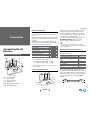
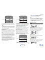
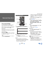
Supplied Accessories
Make sure you have the following accessories:
*
In catalogs and on packaging, the letter at the end of the
product name indicates the color. Specifications and
operations are the same regardless of color.
Indoor FM antenna (➔ page 19)
AM loop antenna (➔ page 19)
Power cord (European and Taiwanese models)
(➔ page 21)
Speaker cable labels (➔ page 12)
Speaker setup microphone (➔ page 25)
Remote controller (RC-868M) and two batteries (AA/R6)
Quick Start Guide
Complies with
IDA Standards
DA106032
23764/SDPPI/2012
2371
TRA
REGISTERED No
ER0086260/12
DEALER No
527090
TA-20120424004

Safety Information and Introduction
En-6
Table of Contents
Safety Information and Introduction
Important Safety Instructions ......................................2
Precautions ...................................................................3
Supplied Accessories...................................................5
Table of Contents..........................................................6
Features .........................................................................7
Front & Rear Panels......................................................8
Front Panel..................................................................8
Display ........................................................................9
Rear Panel ................................................................10
Remote Controller.......................................................11
Controlling the AV Receiver......................................11
Connections
Connecting the AV Receiver......................................12
Connecting Your Speakers .......................................12
Connecting the TV/AV components..........................15
About RIHD-compatible components........................16
Operations that can be performed
with RIHD connection.............................................17
Confirm the settings ..................................................17
Connection Tips ........................................................17
Connecting the Antennas..........................................19
Connecting Onkyo RI Components...........................20
Using Headphones....................................................20
Turning On & Basic Operations
Turning On/Off the AV Receiver ................................21
Connecting the Power Cord......................................21
Turning On ................................................................21
Turning Off ................................................................21
Firmware Update Notification....................................22
About the HYBRID STANDBY indicator....................22
Initial Setup .................................................................22
Selecting the Language
for the On-screen Setup Menus ............................. 22
Audyssey MultEQ: Auto Setup .................................22
Source Connection ...................................................23
Remote Mode Setup.................................................23
Network Connection .................................................23
Terminating the Initial Setup .....................................23
Using the Automatic Speaker Setup.........................24
Performing Wireless LAN Setup ...............................27
Playback
Playback ......................................................................29
Controlling Contents of USB or Network Devices.....30
Understanding Icons on the Display .........................31
Playing an Audio from Bluetooth-enabled Device ....31
Playing a USB Device...............................................32
Listening to TuneIn ...................................................32
Registering Other Internet Radio ..............................34
Changing the Icon Layout
on the Network Service Screen.............................. 34
Playing Music Files on a Server (DLNA) ..................34
Playing Music Files on a Shared Folder ...................36
Remote Playback......................................................37
Listening to AM/FM Radio ........................................38
Playing Audio and Video from Separate Sources.....40
Using the Listening Modes .......................................41
Displaying Source Information..................................49
Using the Sleep Timer ..............................................49
Setting the Display Brightness..................................49
Changing the Input Display.......................................50
Muting the AV Receiver ............................................50
Using the Whole House Mode ..................................50
Using the Home Menu ..............................................51
Advanced Operations
On-screen Setup......................................................... 52
Using the Quick Setup.............................................. 52
Using the Audio Settings of Quick Setup.................. 53
Using the Setup Menu (HOME)................................ 56
Setup Menu Items .................................................... 56
1. Input/Output Assign.............................................. 57
2. Speaker Setup...................................................... 59
3. Audio Adjust ......................................................... 62
4. Source Setup........................................................ 64
5. Listening Mode Preset.......................................... 68
6. Miscellaneous....................................................... 69
7. Hardware Setup.................................................... 69
8. Remote Controller Setup...................................... 73
9. Lock Setup............................................................ 73
Multi Zone ................................................................... 74
Making Multi Zone Connections ............................... 74
Controlling Multi Zone Components ......................... 75
Controlling Other Components
Controlling Other Components................................. 76
Preprogrammed Remote Control Codes .................. 76
Looking up for Remote Control Codes ..................... 76
Entering Remote Control Codes............................... 76
Remapping Colored Buttons .................................... 77
Remote Control Codes for Onkyo Components
Connected via RI ................................................... 77
Resetting the REMOTE MODE Buttons................... 77
Resetting the Remote Controller .............................. 77
Controlling Other Components................................. 78
Using the Onkyo Dock.............................................. 80
Controlling Your iPod/iPhone ................................... 81
Appendix
Troubleshooting ......................................................... 82
Firmware Update ........................................................ 90
About HDMI................................................................. 93
Network/USB Features............................................... 94
License and Trademark Information ........................ 96
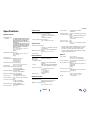
Specifications ............................................................. 97
To reset the AV receiver, see page 82.

Safety Information and Introduction
En-7
Features
Amplifier
• 110 Watts/Channel @ 8 ohms (FTC)
• 170 Watts/Channel @ 6 ohms (IEC)
• 185 Watts/Channel @ 6 ohms (JEITA)
• WRAT–Wide Range Amplifier Technology
(5 Hz to 100 kHz bandwidth)
• Optimum Gain Volume Circuitry
• H.C.P.S. (High Current Power Supply) Massive
High Power Transformer
• 3 Stage Inverted Darlington Amplifier Design
Processing
• THX Select2 Plus Certified
• Incorporates Qdeo™ technology for HDMI Video
Upscaling (to 4K Compatible)
• HDMI (Audio Return Channel, 3D, DeepColor,
x.v.Color, Lip Sync, 4K (up-scaling and
Passthrough), DTS-HD Master Audio, DTS-HD High
Resolution Audio, Dolby TrueHD, Dolby Digital Plus,
DSD and Multi-CH PCM)
• Dolby TrueHD and DTS-HD Master Audio
• Dolby Pro Logic IIz and Audyssey DSX
®
• Non-Scaling Configuration
• A-Form Listening Mode Memory
• Direct Mode
• Pure Audio Mode (European, Australian and Asian
models)
• Music Optimizer for Compressed Digital Music files
• Phase Matching Bass System
• 192 kHz/24-bit D/A Converters
• Powerful and Highly Accurate 32-bit Processing
DSP
• Jitter Cleaning Circuit Technology
Connections
• 8 HDMI Inputs (1 on front panel) and 2 Outputs
• 4K (up-scaling and Passthrough
*
)-compatible HDMI
Inputs
* Compatible with HDMI IN 1 to HDMI IN 4 only
• Onkyo for System Control
• 3 Digital Inputs (1 Optical/2 Coaxial)
• Component Video Switching (1 Input/1 Output)
• Banana Plug-Compatible Speaker Posts
*
In Europe, using banana plugs to connect speakers to an
audio amplifier is prohibited.
• Powered Zone 2
• Bi-Amping Capability for FL/FR with SBL/SBR
• Internet Radio Connectivity
• Network Capability for Streaming Audio Files
• Wi-Fi (Wireless LAN) Connectivity
• Wireless Music Playback via Bluetooth
• Front-Panel USB Input for Memory Devices
• MHL-Enabled AUX Front Input
Miscellaneous
• 40 FM/AM Presets
• Audyssey MultEQ
®
to correct room acoustic
problems
• Audyssey Dynamic EQ
®
for loudness correction
• Audyssey Dynamic Volume
®
to maintain optimal
listening level and dynamic range
• Crossover Adjustment
(40/50/60/70/80/90/100/120/150/200 Hz)
• A/V Sync Control Function (up to 800 ms)
• Auto Standby Function
• On-Screen Display via HDMI
• Preprogrammed -Compatible Remote

Safety Information and Introduction
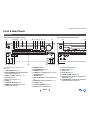
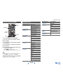
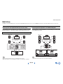
En-8
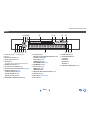
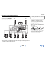
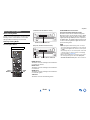
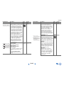
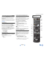
Front & Rear Panels
For detailed information, see the pages in
parentheses.
ON/STANDBY button (21)
MUSIC OPTIMIZER button (North American
and Taiwanese models) (54)
ZONE 2 and ZONE 3 buttons (50, 75)
Wi-Fi indicator (27)
Remote control sensor (11)
Display (9)
LISTENING MODE buttons (41)
DIMMER button (North American and
Taiwanese models) (49)
MEMORY button (38)
TUNING MODE button (38)
HOME button (51)
TUNING / (38), PRESET / (38), cursor
and ENTER buttons
RETURN button
MASTER VOLUME control and indicator (29,
49)
BLUETOOTH button and indicator (31, 73)
PHONES jack (20)
AUX INPUT HDMI/MHL jack (16)
TONE and Tone Level buttons (53)
Input selector buttons (29)
DISPLAY button (49)
USB port (32)
SETUP MIC jack (25)
HYBRID STANDBY indicator (22)
RT/PTY/TP button (European, Australian and
Asian models) (39)
PURE AUDIO button and indicator (European,
Australian and Asian models) (41)
Front Panel
(North American and Taiwanese models) (European, Australian and Asian models)

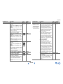
Safety Information and Introduction
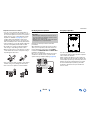
En-9
s
For detailed information, see the pages in
parentheses.
Z2 (Zone 2) indicator (75)
Z3 (Zone 3) indicator (75)
3D indicator
This lights when a 3D input signal is detected.
Headphone indicator (20)
, and cursor indicators (32)
Listening mode and format indicators (41, 68)
Audyssey indicator (24, 64)
Audyssey DSX indicator (45)
Dynamic EQ indicator (64)
Dynamic Vol indicator (64)
M.Opt (Music Optimizer) indicator (54)
Tuning indicators
RDS indicator (excluding North American and
Taiwanese models) (39)
AUTO indicator (38)
TUNED indicator (38)
FM STEREO indicator (38)
MUTING indicator (50)
Input indicators (18)
HDMI indicator (70)
DIGITAL indicator
ARC (Audio Return Channel) indicator (71)
USB indicator (32)
NET indicator (32 to 36, 73)
Message area
SLEEP indicator (49)
Channel/Unit indicators
ch indicator
Hz indicator
m/ft indicator
dB indicator
ASb (Auto Standby) indicator (71)
Display

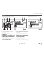
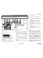
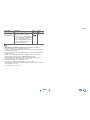
Safety Information and Introduction
En-10
See “Connecting Your Speakers” for connection
(➔ pages 12 to 20).
REMOTE CONTROL jack
COMPONENT VIDEO IN and OUT jacks
ETHERNET port
FM ANTENNA jack and AM ANTENNA terminal
HDMI IN and HDMI output (HDMI OUT MAIN and
HDMI OUT SUB) jacks
SPEAKERS terminals
(CENTER, FRONT, SURROUND, SURROUND
BACK or FRONT HIGH, ZONE 2)
Power cord (North American, Australian and
Asian models)
DIGITAL IN COAXIAL and OPTICAL jacks
GND screw
Composite video and analog audio jacks
(BD/DVD IN, CBL/SAT IN, STB/DVR IN, GAME
IN, PC IN, TV/CD IN, PHONO IN)
MONITOR OUT V jack
SUBWOOFER PRE OUT jacks
ZONE 2/ZONE 3 LINE OUT jacks
AC INLET (European and Taiwanese models)
Rear Panel
(North American, Australian and Asian models) (European and Taiwanese models)

Safety Information and Introduction
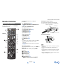
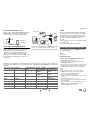
En-11
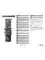
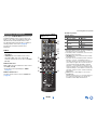
Remote Controller
To control the AV receiver, press RECEIVER to
select Receiver mode.
For detailed information, see the pages in
parentheses.
RECEIVER button (21)
REMOTE MODE/INPUT SELECTOR buttons
(29)
// / and ENTER buttons
Q SETUP button (52)
Listening Mode buttons (41)
DIMMER button (49)
DISPLAY button (49)
MUTING button (50)
VOL / button (29)
RETURN button
HOME button (51)
SLEEP button (49)
Tip
• You can also use the remote controller to control Onkyo
Blu-ray Disc/DVD player, CD player, and other
components.
See “Entering Remote Control Codes” for more details
(➔ page 76).
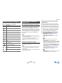
■ Controlling the tuner
To control the AV receiver’s tuner, press TUNER (or
RECEIVER).
You can select AM or FM by pressing TUNER
repeatedly.
/ buttons ( 38)
D.TUN button (38)
DISPLAY button
CH +/– button (39)
Number buttons (38)
*1
These buttons can also be used when a REMOTE
MODE other than Receiver mode is selected.
■ Aiming the remote controller
To use the remote controller, point it at the AV
receiver’s remote control sensor, as shown below.
■ Installing the batteries
Note
• If the remote controller doesn’t work reliably, try replacing
the batteries.
• Don’t mix new and old batteries or different types of
batteries.
• If you intend not to use the remote controller for a long time,
remove the batteries to prevent damage from leakage or
corrosion.
• Remove expired batteries as soon as possible to prevent
damage from leakage or corrosion.
Controlling the AV Receiver
*1
*1
*1
*1
RECEIVER
Remote control sensor
AV receiver
Approx. 16 ft. (5 m)
Batteries (AA/R6)

En-12
Connections
Connecting the AV
Receiver
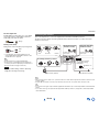
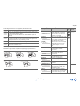
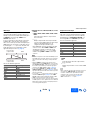
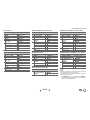
Speaker Configuration
The following table indicates the channels you should
use depending on the number of speakers that you
have.
No matter how many speakers you use, a powered
subwoofer is recommended for a really powerful and
solid bass.
To get the best from your surround sound system,
you need to set the speaker settings automatically
(➔ page 24) or manually (➔ page 59).
*1
Front high and surround back speakers cannot be used
at the same time.
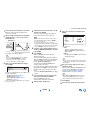
Using Powered Subwoofers
To find the best position for your subwoofer, while
playing a movie or some music with good bass,
experiment by placing your subwoofer at various
positions within the room, and choose the one that
provides the most satisfying results.
You can connect the powered subwoofer with two
SUBWOOFER PRE OUT jacks respectively.
The same signal is output from each jack.
Tip
• If your subwoofer is unpowered and you’re using an
external amplifier, connect the subwoofer pre out jack to an
input on the amplifier.
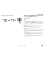
Attaching the Speaker Cable Labels
The speaker terminals are color-coded for
identification purpose.
The supplied speaker cable labels are also color-
coded and you should attach them to the positive (+)
side of each speaker cable in accordance with the
table above. Then all you need to do is to match the
color of each label to the corresponding speaker
terminal.
Connections
Connecting Your Speakers
Front speakers
Center speaker
Surround speakers
Subwoofer(s)
Surround back speakers
Front high speakers
Number of speakers 2 3 4 5 6 7 7
Front speakers ✔✔✔✔✔✔✔
Center speaker ✔✔✔✔✔
Surround speakers ✔✔✔✔✔
Surround back speaker
*1
✔
Surround back speakers
*1
✔
Front high speakers
*1
✔
Speaker Configuration
5.1-channel:
7.1-channel:
+
7.1-channel:
+
Corner
position
1/3 of wall
position
Speaker Color
Front left, Front high left, Zone 2 left White
Front right, Front high right, Zone 2
right
Red
Center Green
Surround left Blue
Surround right Gray
Surround back left Brown
Surround back right Tan

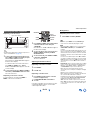
Connections
En-13
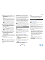
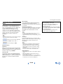
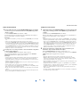
Connecting the Speaker Cables/Powered Subwoofers
Please connect , , , , and for 5.1-channel surround.
• Pay close attention to speaker wiring polarity. In other words, connect positive (+) terminals only to positive (+)
terminals, and negative (–) terminals only to negative (–) terminals. If you get them the wrong way around, the
sound will be out of phase and will sound unnatural.
Surround
speaker R
Surround
speaker L
Surround back or
Front high speaker L
Powered
subwoofer
Gray
Front
speaker L
Front
speaker R
Green White
Red
Center speaker
If you’re using only one surround back
speaker, connect it to the SURROUND
BACK or FRONT HIGH L terminals.
Surround back or
Front high speaker R
Powered
subwoofer
Ta n B ro wn B lu e
• Read the instructions supplied with your speakers.
• By default, speakers for 7.1-channel surround are
configured to use: front right/front left/center/
surround right/surround left/surround back right/
surround back left/subwoofer.
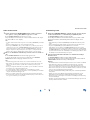
■ Screw-type speaker terminals
Strip 1/2" to 5/8" (12 to 15 mm) of insulation from the
ends of the speaker cables, and twist the bare wires
tightly, as shown.
■ Banana Plugs (North American models)
• If you are using banana plugs, tighten the speaker
terminal before inserting the banana plug.
• Do not insert the speaker code directly into the
center hole of the speaker terminal.
Before connecting the power cord, connect all of
your speakers and AV components. A setup wizard
is launched upon first-time use to let you perform
the settings.
1/2" to 5/8" (12 to 15 mm)

Connections
En-14
■ Speaker Connection Precautions
• You can connect speakers with an impedance of
between 4 and 16 ohms. If the impedance of any of
the connected speakers is 4 ohms or more, but less
than 6 ohms, be sure to set the minimum speaker
impedance to “4ohms” (➔ page 59). If you use
speakers with a lower impedance, and use the
amplifier at high volume levels for a long period of
time, the built-in protection circuit may be activated.
• Unnecessarily long, or very thin speaker cables may
affect the sound quality and should be avoided.
• Be careful not to short the positive and negative
wires. Doing so may damage the AV receiver.
• Make sure the metal core of the wire does not have
contact with the AV receiver’s rear panel. Doing so
may damage the AV receiver.
• Don’t connect more than one cable to each speaker
terminal. Doing so may damage the AV receiver.
• Don’t connect one speaker to several terminals.
Bi-amping the Front Speakers
Bi-amping provides improved bass and treble
performance.
When bi-amping is used, the AV receiver is able to
drive up to a 5.1 speaker system in the main room.
Perform bi-amping connections by using FRONT
terminals and SURROUND BACK or FRONT HIGH
terminals as shown below.
Once you’ve completed the bi-amping connections
and turned on the AV receiver, you must set the
speaker setting to enable bi-amping (➔ page 59).
Using Dipole Speakers
You can use dipole speakers for the surround and
surround back speakers. Dipole speakers output the
same sound in two directions.
Dipole speakers typically have an arrow printed on
them to indicate how they should be positioned. The
surround dipole speakers (a) should be positioned so
that their arrows point toward the TV/screen, while
the surround back dipole speakers (b) should be
positioned so that their arrows point toward each
other, as shown.
Important:
• When making the bi-amping connections, be sure to
remove the jumper bars that link the speakers’ tweeter
(high) and woofer (low) terminals.
• Bi-amping can be used only with speakers that support
bi-amping. Refer to your speaker manual.
Front right Front left
Woofer (low)
Tweeter (high)
bb
aa
TV/screen

Connections
En-15
If you select the input selector button, the signal from
the component connected to the assigned jack is
played.
• Before making any AV connections, read the
manuals supplied with your AV components.
• Push plugs in all the way to make good connections
(loose connections can cause noise or
malfunctions).
• To prevent interference, keep audio and video
cables away from power cords and speaker cables.
Connections
Connecting the TV/AV components
Before connecting the power cord, connect all of your speakers and AV components. To display the setup
menu on the TV screen, connecting the TV to HDMI OUT MAIN is required.
Input selector
buttons
Use this jack to connect to the HDMI input of the
TV. If your TV doesn’t support Audio Return
Channel (ARC)
*1
, you need to connect an optical
digital cable together with the HDMI cable to jack
.
Another TV can be connected to the HDMI OUT
SUB jack.
*1
ARC is the function that carries the audio signal
from the TV to jack . With ARC, a single HDMI
cable can connect the TV and the AV receiver.
Use this jack to connect to your Blu-ray Disc/DVD
player, etc.
Use this jack to connect to the Satellite/cable set-
top box, etc.
Tip
• To listen to the audio of a component connected via HDMI
through your TV’s speakers, enable “HDMI Through”
(
➔ page 70) and set the AV receiver to standby mode.
• In the case of Blu-ray Disc/DVD players, if no sound is
output despite following the above-mentioned procedure,
set your Blu-ray Disc/DVD player’s HDMI audio settings to
PCM.
• Connect a turntable (MM) that has a built-in phono preamp
to TV/CD IN, or connect it to PHONO IN with the phono
preamp turned off. If your turntable (MM) doesn’t have a
phono preamp, connect it to PHONO IN. If your turntable
has a moving coil (MC) type cartridge, you’ll need a
commercially available MC head amp or MC transformer to
connect to PHONO IN. See your turntable’s manual for
details.
If your turntable has a ground wire, connect it to the AV
receiver’s GND screw. With some turntables, connecting
the ground wire may produce an audible hum. If this
happens, disconnect it.
Use this jack to connect to the set top box/digital
video recorder, etc.
Use this jack to connect to the game consoles,
etc.
Use this port to connect to a LAN port on a router
so the AV receiver can be connected to your
home network.
Use jack and terminal here to connect the
supplied FM antenna and AM loop antenna.
Use this jack to make connections using an
analog audio cable.
With this connection, you can also enjoy analog
audio from external components while you are in
Zone 2/3.
Use this jack to make connections using a
component video cable.
Use this jack to connect to the camcorder/MHL-
enabled mobile device, etc.

Connections
En-16
■ MHL (Mobile High-Definition Link)
With its support for MHL (Mobile High-Definition Link),
the AUX (Front) input allows you to deliver high-
definition video from a connected mobile device.
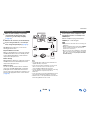
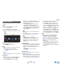
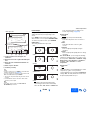
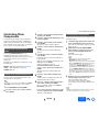
Connecting to the Network (Optional)
The following diagram shows how you can connect
the AV receiver to your home network. In this
example, it’s connected to a LAN port on a router,
which has a 4-port 100Base-TX switch built-in.
Network connection by wireless LAN is possible. See
“Performing Wireless LAN Setup” for connections
(➔ page 27).
Do not connect the AV receiver’s USB port to a USB
port on your computer. Music on your computer
cannot be played through the AV receiver in this way.
The default of the assignment for the input selector buttons and jacks are as shown below. These settings can
be changed. (The assignment for the composite video jacks, analog audio jacks, and HDMI Front jack cannot be
changed.)
MHL-enabled
mobile device, etc.
WAN
LAN
Internet radio
Modem
Computer or media server
Router
Input selector buttons HDMI jacks COMPONENT VIDEO
jacks
DIGITAL IN COAXIAL
and OPTICAL jacks
Composite video and
analog audio jacks
BD/DVD HDMI IN 1 DIGITAL IN
COAXIAL 1
VIDEO/AUDIO IN
BD/DVD
CBL/SAT HDMI IN 2 COMPONENT VIDEO
IN
DIGITAL IN
COAXIAL 2
VIDEO/AUDIO IN
CBL/SAT
STB/DVR HDMI IN 3 VIDEO/AUDIO IN
STB/DVR
GAME HDMI IN 4 VIDEO/AUDIO IN
GAME
PC HDMI IN 5 AUDIO IN PC
AUX HDMI Front
TV/CD DIGITAL IN OPTICAL AUDIO IN TV/CD
PHONO AUDIO IN PHONO
The AV receiver allows interoperability of the CEC
(Consumer Electronics Control) specified in the HDMI
standard, which is known as RIHD. Various linked
operations can be performed by connecting the AV
receiver to an RIHD-compatible TV, player, or
recorder.
Default setting is set to off, so it is required to change
the setting to on.
Perform this setting after the initial setup.
The following components are -compatible
(As of January 2013).
■ TV
•Sharp TV
■ Players/Recorders
• Onkyo and Integra -compatible players
• Toshiba players and recorders
• Sharp players and recorders (only when used
together with Sharp TV)
*
Models other than those mentioned above may have some
interoperability if compatible with CEC, which is part of the
HDMI Standard, but operation cannot be guaranteed.
Note
• For proper linked operations, do not connect more
-compatible components than the quantities
specified below, to the HDMI input terminal.
– Blu-ray Disc/DVD players: up to three.
– Blu-ray Disc/DVD recorders/Digital Video Recorders: up
to three.
– Cable/Satellite Set-top boxes: up to four.
• Do not connect the AV receiver to another AV receiver/AV
amplifier via HDMI.
• Proper linked operations are not guaranteed when more
-compatible components than the above-
mentioned quantities are connected.
About RIHD-compatible components

Connections
En-17
■ For -compatible TV
The following linked operations are enabled by
connecting the AV receiver to an -compatible
TV.
• The AV receiver will enter standby mode when the
TV is set to standby.
• You can set on the menu screen of the TV to either
output the audio from the speakers connected to the
AV receiver, or from the speakers of the TV.
• It is possible to output the audio coming from the
tuner or auxiliary input of your TV to the speakers of
the AV receiver. (A connection such as an optical
digital cable or similar is required in addition to the
HDMI cable.)
• Input to the AV receiver can be selected with the
remote controller of the TV.
• Operations such as volume adjustment or similar for
the AV receiver can be performed from the remote
controller of the TV.
■ For -compatible players/recorders
The following linked operations are enabled by
connecting the AV receiver to an -compatible
player/recorder.
• When playback is started on the player/recorder, AV
receiver will switch to the HDMI input of the
player/recorder that is playing back.
• Operation of the player/recorder is possible using
the remote controller supplied with the AV receiver.
*
Depending on the model used, not all operations may be
available.
Note
• Do not assign an HDMI IN to the TV/CD selector at this
time, otherwise appropriate CEC (Consumer Electronics
Control) operation will not be guaranteed.
1. Turn on the power for all connected components.
2. Turn off the power of the TV, and confirm that the
power of the connected components is turned off
automatically with the link operation.
3. Turn on the power of the Blu-ray Disc/DVD
player/recorder.
4. Start playback on the Blu-ray Disc/DVD
player/recorder, and verify the following:
• The AV receiver automatically turns on, and
selects the input to which the Blu-ray Disc/DVD
player/recorder is connected.
• The TV automatically turns on, and selects the
input to which the AV receiver is connected.
5. Following the operating instructions of the TV,
select “Use the TV speakers” from the menu
screen of the TV, and confirm that the audio is
output from the speakers of the TV, and not from
the speakers connected to the AV receiver.
6. Select “Use the speakers connected from the AV
receiver” from the menu screen of the TV, and
confirm that the audio is output from the speakers
connected to the AV receiver, and not from the TV
speakers.
Note
• Audio from DVD-Audio or Super Audio CD may not output
from the TV speakers. You will be able to output the audio
from the TV speakers by setting the audio output of the
DVD player to 2ch PCM. (It may not be possible depending
on the player models.)
• Even if you set to output audio on the TV speakers, audio
will be output from the speakers connected to the AV
receiver when you adjust the volume or switch the input on
the AV receiver. To output audio from the TV speakers, re-
do the corresponding operations on the TV.
• In case of an connection with and audio
control compatible components, do not connect the
cable at the same time.
• On the TV, when you select anything other than the HDMI
jack to which the AV receiver is connected, the input on the
AV receiver will be switched to “TV/CD”.
• The AV receiver will automatically power on in conjunction
when it determines it to be necessary. Even if the AV
receiver is connected to an compatible TV or
player/recorder, it will not power on if it is not necessary. It
may not power on in conjunction when the TV is set to
output audio from the TV.
• Linked functions with the AV receiver may not work
depending on the component model connected. In such
cases, operate the AV receiver directly.
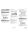
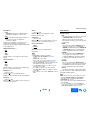
The video and audio signal flow
Connect the AV receiver between the AV
components and the TV. The signal from the AV
components is carried through the AV receiver. You
can enjoy the audio of the TV through the AV
receiver.
Video components can be connected by using any
one of the following video connection formats:
composite video, component video, or HDMI, the
latter offering the best picture quality.
Video input signals flow through the AV receiver as
shown, with composite video and component video
sources all being upconverted for the HDMI output(s).
Operations that can be performed with
RIHD connection
Confirm the settings
Connection Tips
Blu-ray Disc/DVD player, etc.
AV receiver
TV, projector, etc.
Audio
Video, audio
Video, audio

Connections
En-18
The composite video and component video outputs
pass through their respective input signals as they are.
Note
• In order for the AV receiver to upconvert component input
to HDMI output, the source output must be set to 480i/576i.
When signal is input at resolution of 480p/576p and more,
error message will be displayed.
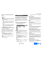
■ Signal Selection
If signals are present at more than one input, the
inputs will be selected automatically in the following
order of priority: HDMI, component video, composite
video.
However, for component video only, regardless of
whether a component video signal is actually present,
if a component video input is assigned to the input
selector, that component video input will be selected.
And if no component video input is assigned to the
input selector, this will be interpreted as no
component video signal being present.
In the Signal Selection Example shown below, video
signals are present at both the HDMI and composite
video inputs. However, the HDMI signal is
automatically selected as the source and the video is
output by the HDMI outputs.
• For optimal video performance, THX recommends
that video signals pass through the system without
upconversion (e.g., component video input passing
through to component video output).
• To by-pass the upconversion, set the “Picture
Mode” setting to “Bypass” (➔ page 66).
Audio components can be connected by using any of
the following audio connection formats: analog,
optical, coaxial, or HDMI.
When choosing a connection format, bear in mind
that the AV receiver does not convert digital input
signals for analog line outputs and vice versa.
If signals are present at more than one input, the
inputs will be selected automatically in the following
order of priority: HDMI, digital, analog.
*1
Depends on the “Audio TV Out (Main)” or “Audio TV
Out (Sub)” setting (➔ pages 70, 71).
*2
This is possible when “Audio Return Channel” is set to
“Auto” (➔ page 71), the TV/CD input selector is
selected, and your TV is ARC capable.
Tip
• When a signal is input via HDMI and the corresponding
input selector is selected, the HDMI indicator lights. In the
case of an optical or coaxial connection, the DIGITAL
indicator lights. In the case of an analog connection, neither
of the HDMI and DIGITAL indicators light.
AV Cables and Jacks
■ HDMI
HDMI connections can carry digital video and audio.
■ Component video
Component video separates the luminance (Y) and
color difference signals (P
B, PR), providing the best
picture quality (some TV manufacturers label their
component video sockets slightly differently).
■ Composite video
Composite video is commonly used on TVs, DVDs,
and other video equipment.
■ Optical digital audio
Optical digital connections allow you to enjoy digital
sound such as PCM
*1
, Dolby Digital or DTS. The
audio quality is the same as coaxial.
IN
MONITOR OUT
Blu-ray Disc/DVD player, etc.
AV receiver
TV, projector, etc.
Composite
Composite
Component
Component
Video Signal Flow Chart
HDMI
HDMI
IN
MONITOR OUT
Blu-ray Disc/DVD player, etc.
TV, projector, etc.
Composite
Composite
Component
Component
Signal Selection Example
HDMI
HDMI
AV receiver
IN
OUT
Blu-ray Disc/DVD player, etc.
AV receiver
TV, projector, etc.
HDMICoaxial Analog
Audio Signal Flow Chart
HDMI
Optical
*1
*1 *1
*1 *2
Green
Blue
Red
Yellow
Y
C
B
/P
B
C
R
/P
R

Connections
En-19
■ Coaxial digital audio
Coaxial digital connections allow you to enjoy digital
sound such as PCM
*1
, Dolby Digital or DTS. The
audio quality is the same as optical.
■ Analog audio (RCA)
Analog audio connections (RCA) carry analog audio.
*1
For PCM signals, the supported sampling rates are
32/44.1/48/88.2/96 kHz. With HDMI connections, 176.4
and 192 kHz are also supported.
Note
• The AV receiver does not support SCART plugs.
• The AV receiver’s optical digital jacks have shutter-type
covers that open when an optical plug is inserted and close
when it’s removed. Push plugs in all the way.
Caution
• To prevent shutter damage, hold the optical plug
straight when inserting and removing.
Orange
White
Red
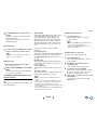
This section explains how to connect the supplied indoor FM antenna and AM loop antenna.
The AV receiver won’t pick up any radio signals without any antenna connected, so you must connect the
antenna to use the tuner.
Note
• Once your AV receiver is ready for use, you’ll need to tune into a radio station and position the antenna to achieve the best
possible reception.
• Keep the AM loop antenna as far away as possible from your AV receiver, TV, speaker cables, and power cords.
Tip
• If you cannot achieve good reception with the supplied indoor FM antenna, try a commercially available outdoor FM antenna
instead.
• If you cannot achieve good reception with the supplied indoor AM loop antenna, try using it with a commercially available
outdoor AM antenna.
Connecting the Antennas
Thumbtacks, etc.
Insert the plug fully
into the jack.
Insert the plug fully
into the jack.
(North American and
Taiwanese models)
(European, Australian
and Asian models)
Push. Insert wire. Release.
Assembling the AM loop antenna
Indoor FM antenna (supplied)AM loop antenna (supplied)
Caution
• Be careful not to injure
yourself when using
thumbtacks.

Connections
En-20
With (Remote Interactive), you can use the
following special functions:
■ System On/Auto Power On
When you start playback on a component connected
via , while the AV receiver is on standby, the AV
receiver will automatically turn on and select that
component as the input source.
■ Direct Change
When playback is started on a component connected
via , the AV receiver automatically selects that
component as the input source.
■ Remote Control
You can use the AV receiver’s remote controller to
control your other -capable Onkyo components,
pointing the remote controller at the AV receiver’s
remote control sensor instead of the component. You
must enter the appropriate remote control code first
(➔ page 77).
Note
• Use only cables for connections. cables are
supplied with Onkyo components.
• Some components have two jacks. You can connect
either one to the AV receiver. The other jack is for
connecting additional -capable components.
• Connect only Onkyo components to jacks. Connecting
other manufacturer’s components may cause a
malfunction.
• Some components may not support all functions. Refer
to the manuals supplied with your Onkyo components.
• While Zone 2/3 is on, the System On/Auto Power On and
Direct Change functions do not work.
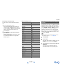
Connecting Onkyo RI Components
1
Make sure that each Onkyo component is
connected with an analog audio cable
(connection
in the hookup examples)
(➔ page 15).
2
Make the connection (see the illustration).
3
If you’re using an RI Dock, or cassette tape
deck, change the Input Display (➔ page 50).
LR
ANALOG
AUDIO OUT
LR
ANALOG
AUDIO OUT
e.g., cassette tape deck
RI Dock
Using Headphones
1
Connect a pair of stereo headphones with a
standard plug (1/4 inch or ø
6.3 mm) to the
PHONES jack.
While the headphones plug is inserted in the
PHONES jack, indicator lights.
Note
• Always turn down the volume before connecting your
headphones.
• While the headphones plug is inserted in the PHONES
jack, the speakers are turned off. (The Zone 2/3
speakers are not turned off.)
• When you connect a pair of headphones, the listening
mode is set to Stereo, unless it’s already set to Stereo,
Mono, Direct, or Pure Audio (European, Australian
and Asian models).
La pagina si sta caricando...
La pagina si sta caricando...
La pagina si sta caricando...
La pagina si sta caricando...
La pagina si sta caricando...
La pagina si sta caricando...
La pagina si sta caricando...
La pagina si sta caricando...
La pagina si sta caricando...
La pagina si sta caricando...
La pagina si sta caricando...
La pagina si sta caricando...
La pagina si sta caricando...
La pagina si sta caricando...
La pagina si sta caricando...
La pagina si sta caricando...
La pagina si sta caricando...
La pagina si sta caricando...
La pagina si sta caricando...
La pagina si sta caricando...
La pagina si sta caricando...
La pagina si sta caricando...
La pagina si sta caricando...
La pagina si sta caricando...
La pagina si sta caricando...
La pagina si sta caricando...
La pagina si sta caricando...
La pagina si sta caricando...
La pagina si sta caricando...
La pagina si sta caricando...
La pagina si sta caricando...
La pagina si sta caricando...
La pagina si sta caricando...
La pagina si sta caricando...
La pagina si sta caricando...
La pagina si sta caricando...
La pagina si sta caricando...
La pagina si sta caricando...
La pagina si sta caricando...
La pagina si sta caricando...
La pagina si sta caricando...
La pagina si sta caricando...
La pagina si sta caricando...
La pagina si sta caricando...
La pagina si sta caricando...
La pagina si sta caricando...
La pagina si sta caricando...
La pagina si sta caricando...
La pagina si sta caricando...
La pagina si sta caricando...
La pagina si sta caricando...
La pagina si sta caricando...
La pagina si sta caricando...
La pagina si sta caricando...
La pagina si sta caricando...
La pagina si sta caricando...
La pagina si sta caricando...
La pagina si sta caricando...
La pagina si sta caricando...
La pagina si sta caricando...
La pagina si sta caricando...
La pagina si sta caricando...
La pagina si sta caricando...
La pagina si sta caricando...
La pagina si sta caricando...
La pagina si sta caricando...
La pagina si sta caricando...
La pagina si sta caricando...
La pagina si sta caricando...
La pagina si sta caricando...
La pagina si sta caricando...
La pagina si sta caricando...
La pagina si sta caricando...
La pagina si sta caricando...
La pagina si sta caricando...
La pagina si sta caricando...
La pagina si sta caricando...
La pagina si sta caricando...
La pagina si sta caricando...
La pagina si sta caricando...
La pagina si sta caricando...
La pagina si sta caricando...
La pagina si sta caricando...
La pagina si sta caricando...
La pagina si sta caricando...
La pagina si sta caricando...
La pagina si sta caricando...
La pagina si sta caricando...
La pagina si sta caricando...
La pagina si sta caricando...
La pagina si sta caricando...
La pagina si sta caricando...
La pagina si sta caricando...
La pagina si sta caricando...
La pagina si sta caricando...
La pagina si sta caricando...
La pagina si sta caricando...
La pagina si sta caricando...
La pagina si sta caricando...
La pagina si sta caricando...
La pagina si sta caricando...
La pagina si sta caricando...
La pagina si sta caricando...
La pagina si sta caricando...
La pagina si sta caricando...
La pagina si sta caricando...
La pagina si sta caricando...
La pagina si sta caricando...
La pagina si sta caricando...
La pagina si sta caricando...
La pagina si sta caricando...
La pagina si sta caricando...
La pagina si sta caricando...
La pagina si sta caricando...
La pagina si sta caricando...
La pagina si sta caricando...
La pagina si sta caricando...
La pagina si sta caricando...
La pagina si sta caricando...
La pagina si sta caricando...
La pagina si sta caricando...
La pagina si sta caricando...
La pagina si sta caricando...
La pagina si sta caricando...
-
 1
1
-
 2
2
-
 3
3
-
 4
4
-
 5
5
-
 6
6
-
 7
7
-
 8
8
-
 9
9
-
 10
10
-
 11
11
-
 12
12
-
 13
13
-
 14
14
-
 15
15
-
 16
16
-
 17
17
-
 18
18
-
 19
19
-
 20
20
-
 21
21
-
 22
22
-
 23
23
-
 24
24
-
 25
25
-
 26
26
-
 27
27
-
 28
28
-
 29
29
-
 30
30
-
 31
31
-
 32
32
-
 33
33
-
 34
34
-
 35
35
-
 36
36
-
 37
37
-
 38
38
-
 39
39
-
 40
40
-
 41
41
-
 42
42
-
 43
43
-
 44
44
-
 45
45
-
 46
46
-
 47
47
-
 48
48
-
 49
49
-
 50
50
-
 51
51
-
 52
52
-
 53
53
-
 54
54
-
 55
55
-
 56
56
-
 57
57
-
 58
58
-
 59
59
-
 60
60
-
 61
61
-
 62
62
-
 63
63
-
 64
64
-
 65
65
-
 66
66
-
 67
67
-
 68
68
-
 69
69
-
 70
70
-
 71
71
-
 72
72
-
 73
73
-
 74
74
-
 75
75
-
 76
76
-
 77
77
-
 78
78
-
 79
79
-
 80
80
-
 81
81
-
 82
82
-
 83
83
-
 84
84
-
 85
85
-
 86
86
-
 87
87
-
 88
88
-
 89
89
-
 90
90
-
 91
91
-
 92
92
-
 93
93
-
 94
94
-
 95
95
-
 96
96
-
 97
97
-
 98
98
-
 99
99
-
 100
100
-
 101
101
-
 102
102
-
 103
103
-
 104
104
-
 105
105
-
 106
106
-
 107
107
-
 108
108
-
 109
109
-
 110
110
-
 111
111
-
 112
112
-
 113
113
-
 114
114
-
 115
115
-
 116
116
-
 117
117
-
 118
118
-
 119
119
-
 120
120
-
 121
121
-
 122
122
-
 123
123
-
 124
124
-
 125
125
-
 126
126
-
 127
127
-
 128
128
-
 129
129
-
 130
130
-
 131
131
-
 132
132
-
 133
133
-
 134
134
-
 135
135
-
 136
136
-
 137
137
-
 138
138
-
 139
139
-
 140
140
-
 141
141
-
 142
142
-
 143
143
-
 144
144


ONKYO TX-NR727 Manuale del proprietario
- Categoria
- Ricevitori AV
- Tipo
- Manuale del proprietario
in altre lingue
- English: ONKYO TX-NR727 Owner's manual
Documenti correlati
-
ONKYO HT-RC440 Manuale del proprietario
-
ONKYO MS-100 HCP and Manuale utente
-
ONKYO TX-NR414 Manuale utente
-
ONKYO TX-NR 616 Manuale utente
-
ONKYO TX-NR 717 Manuale utente
-
-
ONKYO TX-NR515 Manuale utente
-
ONKYO RBX-500 Manuale utente
-
ONKYO TX-NR838 Manuale del proprietario
-
ONKYO CS-265DAB Manuale utente
Altri documenti
-
Sharp XL-B512(BK) Manuale del proprietario
-
Pioneer DM-40BT-W White Manuale utente
-
Sony HT-ST3 Guida utente
-
Sharp XL-B512 Manuale utente
-
Revo Heritage G1 & G2 Manuale del proprietario
-
Philips WAS6050/05 Manuale utente
-
TEAC NS-X1 Manuale del proprietario
-
Pioneer XW-BTS5 Manuale utente
-
Arcam UDP411 Manuale utente
-
Tascam PA-R100 Remote Control Code