
CGC
CO2 COOLERS
MANUALE TECNICO
Aeroevaporatori a soffitto
BETRIEBSANLEITUNG
Deckenluftverdampfer
TECHNICAL MANUAL
Ceiling unit coolers
MANUAL TECNICO
Aeroevaporadores de techo
MANUEL TECHNIQUE
Evaporateurs plafonniers
ТЕХНИЧЕСКОЕ РУКОВОДСТВО
Потолочные воздухоохладители


1
www.modine.com
CGC
Indice
- Avvertenze
. . . . . . . . . . . . . . . . . . . . . . . . . . . . . . . . . . . . . . . . . . . . . . . . . . . . . . . . . . . . . . . . . . . . . . .2
- Ispezione - Trasporto
. . . . . . . . . . . . . . . . . . . . . . . . . . . . . . . . . . . . . . . . . . . . . . . . . . . . . . . . . .2
- Condizioni da verificare per una corretta
messa in opera
. . . . . . . . . . . . . . . . . . . . . . . . . . . . . . . . . . . . . . . . . . . . . . . . . . . . . . . . . . . . . . . . . .2
- Manutenzione generale
. . . . . . . . . . . . . . . . . . . . . . . . . . . . . . . . . . . . . . . . . . . . . . . . . . . . . .2
- Pericoli
. . . . . . . . . . . . . . . . . . . . . . . . . . . . . . . . . . . . . . . . . . . . . . . . . . . . . . . . . . . . . . . . . . . . . . . . . . . . .2
- Norme di riferimento
. . . . . . . . . . . . . . . . . . . . . . . . . . . . . . . . . . . . . . . . . . . . . . . . . . . . . . . . . . .2
- Avvertenze per una corretta installazione
. . . . . . . . . . . . . . . . . . . . . . . . . . . . . . .3
- Caratteristiche costruttive e dimensionali
. . . . . . . . . . . . . . . . . . . . . . . . . . . . . . .3
- Schema di collegamento dei motoventilatori
. . . . . . . . . . . . . . . . . . . . . . . . . . .5
- Suggerimenti per un corretto accesso
all’apparecchio
. . . . . . . . . . . . . . . . . . . . . . . . . . . . . . . . . . . . . . . . . . . . . . . . . . . . . . . . . . . . . . . . . .6
- Schema di collegamento e potenze delle
resistenze elettriche
. . . . . . . . . . . . . . . . . . . . . . . . . . . . . . . . . . . . . . . . . . . . . . . . . . . . . . . . . . .6
- Garanzie
. . . . . . . . . . . . . . . . . . . . . . . . . . . . . . . . . . . . . . . . . . . . . . . . . . . . . . . . . . . . . . . . . . . . . . . . .52
Index
- Hinweise
. . . . . . . . . . . . . . . . . . . . . . . . . . . . . . . . . . . . . . . . . . . . . . . . . . . . . . . . . . . . . . . . . . . . . . . . .10
- Kontrolle - Transport
. . . . . . . . . . . . . . . . . . . . . . . . . . . . . . . . . . . . . . . . . . . . . . . . . . . . . . . . .10
- Hinweise für eine korrekte Inbetriebnahme
. . . . . . . . . . . . . . . . . . . . . . . . . . .10
- Allgemeine Wartung
. . . . . . . . . . . . . . . . . . . . . . . . . . . . . . . . . . . . . . . . . . . . . . . . . . . . . . . . .10
- Gefahren
. . . . . . . . . . . . . . . . . . . . . . . . . . . . . . . . . . . . . . . . . . . . . . . . . . . . . . . . . . . . . . . . . . . . . . . .10
- Bezugsnormen
. . . . . . . . . . . . . . . . . . . . . . . . . . . . . . . . . . . . . . . . . . . . . . . . . . . . . . . . . . . . . . . .10
- Hinweise für eine korrekte Aufstellung
. . . . . . . . . . . . . . . . . . . . . . . . . . . . . . . . . .11
- Konstruktionseigenschaften und
Abmessungen
. . . . . . . . . . . . . . . . . . . . . . . . . . . . . . . . . . . . . . . . . . . . . . . . . . . . . . . . . . . . . . . . . .11
- Anschlußplan der Motorventilatoren
. . . . . . . . . . . . . . . . . . . . . . . . . . . . . . . . . . . .13
- Ratschläge für einen korrekten Zugang
zum Gerät
. . . . . . . . . . . . . . . . . . . . . . . . . . . . . . . . . . . . . . . . . . . . . . . . . . . . . . . . . . . . . . . . . . . . . . .14
- Anschlußplan und Leistungen der
Heizstäbe
. . . . . . . . . . . . . . . . . . . . . . . . . . . . . . . . . . . . . . . . . . . . . . . . . . . . . . . . . . . . . . . . . . . . . . .14
- Gewährleistung
. . . . . . . . . . . . . . . . . . . . . . . . . . . . . . . . . . . . . . . . . . . . . . . . . . . . . . . . . . . . . . . .52
Index
- Important
. . . . . . . . . . . . . . . . . . . . . . . . . . . . . . . . . . . . . . . . . . . . . . . . . . . . . . . . . . . . . . . . . . . . . . . .18
- Inspection - Transport
. . . . . . . . . . . . . . . . . . . . . . . . . . . . . . . . . . . . . . . . . . . . . . . . . . . . . . .18
- For a proper installation
. . . . . . . . . . . . . . . . . . . . . . . . . . . . . . . . . . . . . . . . . . . . . . . . . . . . .18
- General maintenance
. . . . . . . . . . . . . . . . . . . . . . . . . . . . . . . . . . . . . . . . . . . . . . . . . . . . . . .18
- Hazards / Risks
. . . . . . . . . . . . . . . . . . . . . . . . . . . . . . . . . . . . . . . . . . . . . . . . . . . . . . . . . . . . . . .18
- Reference standards
. . . . . . . . . . . . . . . . . . . . . . . . . . . . . . . . . . . . . . . . . . . . . . . . . . . . . . . .18
- Instructions for a correct installation
. . . . . . . . . . . . . . . . . . . . . . . . . . . . . . . . . . . . .19
- Manufacturing and dimensional features
. . . . . . . . . . . . . . . . . . . . . . . . . . . . . .19
- Fan motor connection scheme
. . . . . . . . . . . . . . . . . . . . . . . . . . . . . . . . . . . . . . . . . . .21
- Recommendations for a proper access to model
. . . . . . . . . . . . . . . . . . .22
- Electric heater connection schemes
and electric power
. . . . . . . . . . . . . . . . . . . . . . . . . . . . . . . . . . . . . . . . . . . . . . . . . . . . . . . . . . . .22
- Warranty
. . . . . . . . . . . . . . . . . . . . . . . . . . . . . . . . . . . . . . . . . . . . . . . . . . . . . . . . . . . . . . . . . . . . . . . . .52
Indice
- Advertencias
. . . . . . . . . . . . . . . . . . . . . . . . . . . . . . . . . . . . . . . . . . . . . . . . . . . . . . . . . . . . . . . . . . .26
- Inspección - Transporte
. . . . . . . . . . . . . . . . . . . . . . . . . . . . . . . . . . . . . . . . . . . . . . . . . . . . .26
- Condiciones a verificar para una correcta
puesta en marcha
. . . . . . . . . . . . . . . . . . . . . . . . . . . . . . . . . . . . . . . . . . . . . . . . . . . . . . . . . . . .26
- Manutención general
. . . . . . . . . . . . . . . . . . . . . . . . . . . . . . . . . . . . . . . . . . . . . . . . . . . . . . . .26
- Peligros
. . . . . . . . . . . . . . . . . . . . . . . . . . . . . . . . . . . . . . . . . . . . . . . . . . . . . . . . . . . . . . . . . . . . . . . . . .26
- Normas de referencia
. . . . . . . . . . . . . . . . . . . . . . . . . . . . . . . . . . . . . . . . . . . . . . . . . . . . . . .26
- Advertencias para una correcta instalación
. . . . . . . . . . . . . . . . . . . . . . . . . . .27
- Características constructivas y
dimensionales
. . . . . . . . . . . . . . . . . . . . . . . . . . . . . . . . . . . . . . . . . . . . . . . . . . . . . . . . . . . . . . . . .27
- Esquema de conexión motoventiladores
. . . . . . . . . . . . . . . . . . . . . . . . . . . . . .29
- Sugerencias para un correcto acceso
al aparato
. . . . . . . . . . . . . . . . . . . . . . . . . . . . . . . . . . . . . . . . . . . . . . . . . . . . . . . . . . . . . . . . . . . . . . .30
- Esquema de conexión y potencia
de las resistencias eléctricas
. . . . . . . . . . . . . . . . . . . . . . . . . . . . . . . . . . . . . . . . . . . . . .30
- Garantias
. . . . . . . . . . . . . . . . . . . . . . . . . . . . . . . . . . . . . . . . . . . . . . . . . . . . . . . . . . . . . . . . . . . . . . . .52
Index
- Attention
. . . . . . . . . . . . . . . . . . . . . . . . . . . . . . . . . . . . . . . . . . . . . . . . . . . . . . . . . . . . . . . . . . . . . . . . .34
- Inspection - Transport
. . . . . . . . . . . . . . . . . . . . . . . . . . . . . . . . . . . . . . . . . . . . . . . . . . . . . . .34
- Conditions à vérifier pour une
mise en marche correcte
. . . . . . . . . . . . . . . . . . . . . . . . . . . . . . . . . . . . . . . . . . . . . . . . . . .34
- Entretien général
. . . . . . . . . . . . . . . . . . . . . . . . . . . . . . . . . . . . . . . . . . . . . . . . . . . . . . . . . . . . . .34
- Dangers
. . . . . . . . . . . . . . . . . . . . . . . . . . . . . . . . . . . . . . . . . . . . . . . . . . . . . . . . . . . . . . . . . . . . . . . . .34
- Normes de référence
. . . . . . . . . . . . . . . . . . . . . . . . . . . . . . . . . . . . . . . . . . . . . . . . . . . . . . . .34
- Instructions pour une installation correcte
. . . . . . . . . . . . . . . . . . . . . . . . . . . . .35
- Caractéristiques constructives et
dimensionnelles
. . . . . . . . . . . . . . . . . . . . . . . . . . . . . . . . . . . . . . . . . . . . . . . . . . . . . . . . . . . . . . .35
- Schéma de connexion motoventilateurs
. . . . . . . . . . . . . . . . . . . . . . . . . . . . . . .37
- Instructions pour accéder à l’appareil
. . . . . . . . . . . . . . . . . . . . . . . . . . . . . . . . . . .38
- Schéma de connexion et puissances
des résistances électriques
. . . . . . . . . . . . . . . . . . . . . . . . . . . . . . . . . . . . . . . . . . . . . . . .38
- Garantie
. . . . . . . . . . . . . . . . . . . . . . . . . . . . . . . . . . . . . . . . . . . . . . . . . . . . . . . . . . . . . . . . . . . . . . . . .52
Содержание
- Меры предосторожности
. . . . . . . . . . . . . . . . . . . . . . . . . . . . . . . . . . . . . . . . . . . . . . . . .42
- Осмотр - Транспортировка
. . . . . . . . . . . . . . . . . . . . . . . . . . . . . . . . . . . . . . . . . . . . . . .42
- Условия для выполнения корректного
ввода в эксплуатацию
. . . . . . . . . . . . . . . . . . . . . . . . . . . . . . . . . . . . . . . . . . . . . . . . . . . . .42
- Общее техобслуживание
. . . . . . . . . . . . . . . . . . . . . . . . . . . . . . . . . . . . . . . . . . . . . . . . .42
- Опасность/ Риски
. . . . . . . . . . . . . . . . . . . . . . . . . . . . . . . . . . . . . . . . . . . . . . . . . . . . . . . . . . . .42
- Ссылка на стандарты
. . . . . . . . . . . . . . . . . . . . . . . . . . . . . . . . . . . . . . . . . . . . . . . . . . . . . .42
- Меры предосторожности
для корректной установки
. . . . . . . . . . . . . . . . . . . . . . . . . . . . . . . . . . . . . . . . . . . . . . .43
- Конструктивные
и пространственные характеристики
. . . . . . . . . . . . . . . . . . . . . . . . . . . . . . . .43
- Схема подключения мотовентиляторов
. . . . . . . . . . . . . . . . . . . . . . . . . . . .45
- Рекомендации по корректному
доступу к аппарату
. . . . . . . . . . . . . . . . . . . . . . . . . . . . . . . . . . . . . . . . . . . . . . . . . . . . . . . . . .46
- Схема подключений и мощностей
электрических сопротивлений
. . . . . . . . . . . . . . . . . . . . . . . . . . . . . . . . . . . . . . . . .46
- Гарантии
. . . . . . . . . . . . . . . . . . . . . . . . . . . . . . . . . . . . . . . . . . . . . . . . . . . . . . . . . . . . . . . . . . . . . . . .52
Index

2
www.modine.com
Attenzione
Prima di effettuare qualsiasi intervento di manutenzione, accertarsi che l’alimentazione elettrica sia scollegata dalla fonte principale: le
parti elettriche potrebbero essere collegate ad un controllo automatico.
Avvertenze
1. Conservare questo manuale tecnico per tutto il periodo di vita
del modello.
2. Leggere con attenzione il manuale prima dell’installazione e
prima di qualsiasi operazione sul modello.
3. Impiegare il modello esclusivamente per lo scopo per cui é
stato progettato: l’uso improprio esonera il costruttore da qual-
siasi responsabilità.
Ispezione - Trasporto
1. Al ricevimento del modello controllare immediatamente il suo
stato; contestare subito alla compagnia di trasporto qualsiasi
eventuale danno.
2. Durante il trasporto evitare di esercitare pressioni improprie
sull’imballaggio, che va mantenuto comunque sempre nella
posizione indicata sullo stesso.
3. Disimballare il modello il più vicino possibile al luogo di installa-
zione. Una volta disimballato, evitare urti ai componenti.
4. Durante l’installazione e la movimentazione del modello utiliz-
zare appositi guanti protettivi per evitare di ferirsi con le parti
taglienti (es. alette) del modello.
Condizioni da verificare per una
corretta messa in opera
1. Verificare la tenuta delle strutture di sostegno rispetto al peso
dell’apparecchio.
2. Verificare che il modello venga installato orizzontalmente.
3. Assicurare un volume libero adeguato (circa il 30% del volume
interno della cella) per una corretta circolazione dell’aria in
aspirazione e scarico.
Particolari condizioni di installazione o funzionamento quali
celle basse, travature a soffitto, stoccaggi eccessivi, impedi-
menti al getto e/o all’aspirazione dell’aria, formazione impro-
pria di brina dovuta ad eccessiva immissione di umidità nella
cella, possono influenzare negativamente le prestazioni
dichiarate e creare difettosità nei modelli.
I modelli standard possono non essere adatti ad operare in
tunnel o celle di abbattimento/surgelamento rapido.
4. I modelli sono equipaggiati con motoventilatori assiali, quindi
non adatti ad essere canalizzati o comunque a sopportare pre-
valenze statiche aggiuntive.
5. Verificare che le condizioni di funzionamento (temperature e
pressioni) siano conformi a quelle di progetto.
6. Prestare particolare cura in fase di collegamento affinchè non si
deformino i capillari e non si modifichi la posizione del distributore.
7. In caso di più modelli installati a breve distanza l’uno dall’altro,
evitare sbrinamenti alternati.
8. Installare sugli scarichi condensa gli opportuni sifoni e verificar-
ne l'efficacia in tutte le temperature di utilizzo.
9. Evitare l'installazione degli aeroevaporatori vicino alle porte
delle celle.
10. Collocare la sonda di temperatura per il fine sbrinamento nelle
zone più fredde degli scambiatori, ovvero quelle zone che ten-
dono a ghiacciarsi maggiormente (al termine del ciclo non deve
rimanere ghiaccio sui modelli). La posizione di questo dispositi-
vo non può essere definita a priori, in quanto varia in relazione
al tipo di cella e al tipo di impianto.
11. Verificare che la linea elettrica di alimentazione sia adeguata
alle caratteristiche elettriche dell’apparecchio.
12. Assicurarsi che tutti i collegamenti elettrici siano in accordo con
le norme vigenti.
13. Le unità sono predisposte per il collegamento elettrico a terra.
L’installattore e/o il conduttore dell’unità sono tenuti a garantire
la presenza di un efficiente collegamento alla terra di protezio-
ne contro i contatti elettrici indiretti.
A richiesta i modelli possono essere forniti con scambiatori,
sbrinamenti e motoventilatori diversi dallo standard.
Le resistenze elettriche impiegate per l’eventuale sbrinamento
sono alloggiate in scatola di derivazione in materiale termopla-
stico (protezione contro il contatto elettrico diretto di classe II)
aventi grado di protezione IP 54.
14. Ad installazione completata rimuovere la pellicola protettiva
che ricopre il modello.
15. L’accessibilità al modello, per qualsiasi tipo di intervento, deve
essere riservata al personale qualificato alla conduzione del-
l’impianto, secondo le norme vigenti.
Manutenzione generale
1. Verificare periodicamente i fissaggi, le connessioni elettriche e i
collegamenti all’impianto frigorifero.
2. Provvedere alla pulizia periodica dell’apparecchio, per evitare
accumuli di sostanze nocive. Si consiglia l’utilizzo di normale
acqua saponata, evitando solventi, agenti aggressivi, abrasivi o
a base di ammoniaca.
3. In caso di sostituzioni di resistenze elettriche prestare particola-
re attenzione nelle fasi di installazione per evitare danni alle
vulcanizzazioni; ripristinare correttamente i collegamenti e i
sistemi di fissaggio esistenti per evitare movimenti delle stesse
durante il funzionamento.
Tali operazioni dovranno essere effettuate da personale
esperto e qualificato.
Pericoli
1. Pericolo di elettrocuzione. Il modello è provvisto
di elettroventilatori e resistestenze elettriche di
sbrinamento. La tensione di alimentazione è di
400V AC. Utilizzare sistemi di sicurezza elettrica
previsti dalla normativa vigente.
2. Pericolo di ustione. Le resistenze elettriche di
sbrinamento possono raggiungere temperature
superficiali di 350°C.
3. Pericolo di taglio. Lo scambiatore di calore è
costituito da alette con bordi taglienti e la
carrozzeria da parti in lamiera.
4. Pericolo parti in movimento. Il modello è provvisto
di elettroventilatori dotati di griglia di protezione
esterna.
5. Pericolo di schiacciamento. Il modello può pesare
oltre 500 kg.
Norme di riferimento
- DIRETTIVA MACCHINE 2006/42/EC
- DIRETTIVA BASSA TENSIONE 2014/35/UE
- DIRETTIVA COMP. ELETTROMAGNETICA 2014/30/UE
- DIRETTIVA PED 2014/68/UE
- DIRETTIVA ERP 2009/125/EC

Italiano
3
www.modine.com
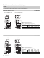
22,5
17,5
30
10
==
P1
135
A
B135
100
336
509
431
387
400 min.
P1 P1
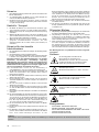
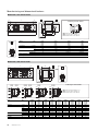
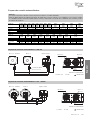
407
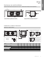
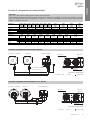
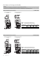
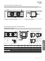
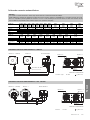
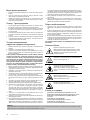
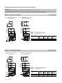
Caratteristiche costruttive e dimensionali
Particolare
di fissaggio
Modello con ventola ø 250 mm
Avvertenze per una corretta installazione
Distanza minima laterale dalla parete lato resistenze e distanza minima dalla parete lato aspirazione
In fase di installazione rispettare la quota minima
A+250 mm per poter togliere/inserire le resistenze.
In fase di installazione rispettare la quota minima di
400 mm per un buon funzionamento del motore.
251 E4R 251 E4 252 G4 252 E4 253 G4 253 E4 254 G4 254 E4
251 E6R 251 E6 252 G6 252 E6 253 G6 253 E6 254 G6 254 E6
251 E8R 251 E8 252 G8 252 E8 253 G8 253 E8 254 G8 254 E8
1x250 1x250 2x250 2x250 3x250 3x250 4x250 4x250
674 774 1224 1224 1674 1674 2124 2124
380 480 930 930 1380 1380 1830 1830
12 12 12 12 12 12 12 12
12 12 12 12 12 12 12 12
1" 1" 1" 1" 1" 1" 1" 1"
14 16 24 26 33 36 42 46
Modello CGC
Motoventilatori
n° x Ø mm
Dimensioni A
B
Attacchi scamb.
In tube (mm)
Out tube (mm)
Attacco scarico Ø (GAS)
Peso netto kg
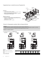
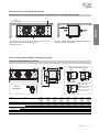
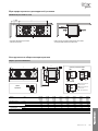
Particolari di posizionamento resistenze
3RR 4RR
4RR (251ExR)
RBA - Resistenza elettrica di
alta potenza nella batteria.
RBB - Resistenza elettrica di
bassa potenza nella batteria.
RSA - Resistenza elettrica
sullo sgocciolatoio interno.

4
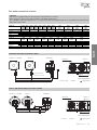
www.modine.com
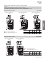
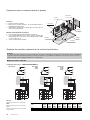
468
424
336
561
400 min.
135 135B
A
22,5
17,5
30
10
==
100
P1
P1 P1
407
Particolare
di fissaggio
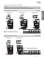
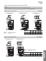
Particolari di posizionamento resistenze
RBA - Resistenza elettrica di alta potenza nella batteria.
RBB - Resistenza elettrica di bassa potenza nella batteria.
RSA - Resistenza elettrica sullo sgocciolatoio interno.
RBA2
RSA1
RBA1
RBB1
RSA1
RBA1
RBA2
RBB1
RBB2
RBA1
RBA2
RSA1
RSA1
RBB1
RBB3
RBB2
RBA1
RBA3
RBA2
RBA4
RBB1
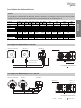
35*F4 ED
35*F6 ED
35*F8 ED
35*E4 ED
35*E6 ED
35*E8 ED
35*E4 EDP
35*E6 EDP
35*E8 EDP
35*F4 EDP
35*F6 EDP
35*F8 EDP
35*A4 ED
35*A6 ED
35*A8 ED
35*A4 EDP
35*A6 EDP
35*A8 EDP
400 min.
135 135B
D C
A
544
499
100
382
608
P1P1
453
22,5
17,5
30
10
==
P1
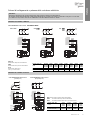
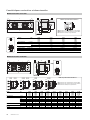
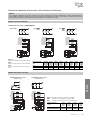
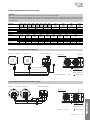
Modello CGC 351 E4 351A4 352 E4 352 A4 353 F4 353A4 354 F4 354 A4 355 A4
351 E6 351A6 352 E6 352 A6 353 F6 353A6 354 F6 354 A6 355 A6
351 E8 351A8 352 E8 352 A8 353 F8 353A8 354 F8 354 A8 355 A8
Motoventilatori n° x Ø 1x350 1x350 2x350 2x350 3x350 3x350 4x350 4x350 5x350
Dimensioni A mm 875 875 1425 1425 1975 1975 2525 2525 3075
B mm 580 580 1130 1130 1680 1680 2230 2230 2780
C mm ------1115 1115 1665
D mm ------1115 1115 1115
In tube (mm) 12 12 12 12 12 12 12 16 16
Out tube (mm) 12 12 12 12 (A8 16) 16 16 (A8 22) 16 (F8 22) 22 22
Attacco scarico Ø (GAS) 1” 1” 1” 1” 1” 1” 1” 1” 1”
Peso netto kg 24 29 45 53 64 69 85 92 113
Particolari di posizionamento resistenze
Modello con ventola ø 350 mm
Attacchi scambiatore
Modello con ventola ø 315 mm
RBA - Resistenza elettrica di alta potenza nella batteria.
RBB - Resistenza elettrica di bassa potenza nella batteria.
RSA - Resistenza elettrica sullo sgocciolatoio interno.
Particolare
di fissaggio
Caratteristiche costruttive e dimensionali
311F4 312F4 313F4 314F4
311F6 312F6 313F6 314F6
311F8 312F8 313F8 314F8
1x315 2x315 3x315 4x315
874 1424 1974 2524
580 1130 1680 2230
12 12 12 12
12 12 12 (F8 16) 16 (F8 22)
1" 1" 1" 1"
22 37 52 67
Modello CGC
Motoventilatori
n° x Ø mm
Dimensioni A
B
Attacchi
In tube (mm)
scambiatore Out tube (mm)
Attacco scarico Ø (GAS)
Peso netto kg

Italiano
5
www.modine.com
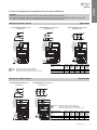
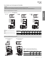
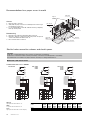
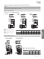
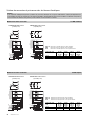
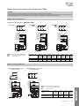
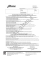
Schema di collegamento dei motoventilatori
Attenzione
I motori sono dotati di termocontatti di protezione interni a riarmo automatico.
Prima di utilizzare sistemi di regolazione del numero di giri dei motori verificare la compatibilità con i motori stessi, sistemi non compati-
bili possono generare rumorosità e danneggiamenti; il costruttore non si assume responsabilità alcuna sulle prestazioni dei modelli equi-
paggiati con sistemi di regolazione.
L N
Schema di collegamento motoventilatori ø 250 mm
Motore n. 2… (eventuali) Motore n. 1 Scatola di derivazione
Connessioni cavi rapida
Scatola di
derivazione
Motore n. 2…
(eventuale)
Motore n. 1
Alimentazione: 230V/1/50-60 Hz
L = marrone o grigio N = blu
= giallo / verde
Alimentazione: 230V/1/50-60 Hz
L = marrone N = blu
= giallo / verde
Schema di collegamento motoventilatori ø 315 - 350 mm
Motore n. 2… (eventuali) Motore n. 1 Scatola di derivazione
Motore n. 2…
(eventuale)
Motore n. 1
Modello CGC 251 E4R 251 E4 252G4 252 E4 253G4 253 E4 254G4 254 E4 311F4 312F4 313F4 314F4
251 E6R 251 E6 252G6 252 E6 253G6 253 E6 254G6 254 E6 311F6 312F6 313F6 314F6
251 E8R 251 E8 252G8 252 E8 253G8 253 E8 254G8 254 E8 311F8 312F8 313F8 314F8
Motori 1 x 250 2 x 250 3 x 250 4 x 250 1 x 315 2 x 315 3 x 315 4 x 315
Frequenza Hz 50 60 50 60 50 60 50 60 50 60 50 60 50 60 50 60
Assorbimento A 0,68 - 1,36 - 2,04 - 2,72 - 0,52 0,66 1,04 1,32 1,56 1,98 2,08 2,64
Motori W 95 - 190 - 285 - 380 - 110 148 220 296 330 444 440 592
RPM 1300 1550 1300 1550 1300 1550 1300 1550 1350 1490 1350 1490 1350 1490 1350 1490
Modello CGC 351 E4 351A4 352 E4 352 A4 353 F4 353A4 354 F4 354 A4 355 A4
351 E6 351A6 352 E6 352 A6 353 F6 353A6 354 F6 354 A6 355 A6
351 E8 351A8 352 E8 352 A8 353 F8 353A8 354 F8 354 A8 355 A8
Motori 1 x 350 2 x 350 3 x 350 4 x 350 5 x 350
Frequenza Hz 50 60 50 60 50 60 50 60 50 60
Assorbimento A 0,96 1,08 1,92 2,16 2,88 3,24 3,84 4,32 4,80 5,40
Motori W 185 250 370 500 555 750 740 1000 925 1250
RPM 1420 1660 1420 1660 1420 1660 1420 1660 1420 1660
Scatola di
derivazione

6
www.modine.com
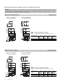
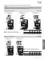
Accesso
1. Smontare il tubo di scarico condensa.
2. Accertarsi che la vaschetta sia libera da eventuali residui di
ghiaccio prima di rimuoverla svitando le viti “A”.
3. Allentare le viti autofilettanti “B”, senza toglierle completamen-
te, quindi sfilare il coperchio laterale.
Riposizionamento
1. Ricollocare il coperchio laterale e fissarlo mediante le viti “B”.
2. Rimettere la vaschetta in posizione, avendo cura che i coper-
chi laterali siano interni alla stessa,
quindi fissarla con le viti “A”.
3. Rimontare il tubo di scarico condensa.
Sostegni
Coperchio
laterale
Scatola di
derivazione
Vaschetta
Scarico condensa
Sgocciolatoio
interno
Convogliatore
Suggerimenti per un corretto accesso all’apparecchio
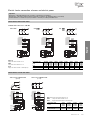
Schemi di collegamento e potenze delle resistenze elettriche
Attenzione
È d’obbligo l’applicazione di opportuni sistemi di protezione termica sulle linee di alimentazione.
Provvedere periodicamente alla verifica delle funzionalità di tutte le resistenze per evitare accumuli dannosi di ghiaccio sui modelli.
Il costruttore non risponde in alcun modo di difettosità create da malfunzionamenti non rilevati.
Modello CGC “ED” 251E4R 251E4 252G4 252E4 253G4 253E4 254G4 254E4
ø 250 251E6R 251E6 252G6 252E6 253G6 253E6 254G6 254E6
251E8R 251E8 252G8 252E8 253G8 253E8 254G8 254E8
Ranghi 4 RR 4 RR 3 RR 4 RR 3 RR 4 RR 3 RR 4 RR
Potenza totale (W) 750 1125 2250 2250 3325 3325 4375 4375
RBA (1-2)
Resistenze di alta potenza nella batteria.
RBB1
Resistenza di bassa potenza nella batteria.
RSA1
Resistenza di alta potenza
sullo sgocciolatoio interno.
RBB1
RBA1
RSA1
L
N
N
RBB1
RBA1
RSA1
P.E.
N
L
L
RBB1
RBA1
RSA1
L
N
N
RBB1
RBA1
RSA1
P.E.
N
L
L
RBA2
RBA1
RSA1
L
N
N
RBA2
RBA1
RSA1
P.E.
N
L
L
R
S
T
N
RBB1
RSA1
RBA1
R
S
T
N
RBB1
RSA1
RBA1
R
S
T
N
RBA2
RSA1
RBA1
N
RBB1
RBA1
RSA1
P.E.
N
R
U
RBB1
RBA1
RSA1
V
W
S
T
N
P.E.
N
R
U
V
W
S
T
RBA2
RBA1
RSA1
N
P.E.
N
R
U
V
W
S
T
CGC 251ExR CGC 252Gx
253Gx
254Gx
CGC 251Ex
252Ex
253Ex
254Ex
Modello con ventola ø 250 mm
COLLEGAMENTO 400V/3/50 Hz PREDISPOSTO

Italiano
7
www.modine.com
Schemi di collegamento e potenze delle resistenze elettriche
RSA1
RBA1
RBA2
RBB1
U
V
W
N
N
W
PE
V
U
R
S
T
N
R
S
T
N
RBB1
RSA1
RBA2
RBA1
RSA1
RBA1
N
L
N
RBB1
RBA2
RBA1
RSA1
L
N
L
N
W
V
U
RBA2
RBB1
PE
Modello CGC “ED” 311F4 321F4 313F4 314F4
ø 315 311F6 321F6 313F6 314F6
311F8 321F8 313F8 314F8
Ranghi 5 RR 5 RR 5RR 5 RR
Potenza totale (W) 1750 3150 4900 6300
COLLEGAMENTO 400V/3/50 Hz COLLEGAMENTO 230V/1/50 Hz
(predisposto) (da predisporre)
Modello con ventola ø 315 mm
RBA (1-2) Resistenze di alta potenza nella batteria.
RBB1 Resistenza di bassa potenza nella batteria.
RSA1 Resistenza di alta potenza sullo sgocciolatoio interno.
Attenzione
È d’obbligo l’applicazione di opportuni sistemi di protezione termica sulle linee di alimentazione.
Provvedere periodicamente alla verifica delle funzionalità di tutte le resistenze per evitare accumuli dannosi di ghiaccio sui modelli.
Il costruttore non risponde in alcun modo di difettosità create da malfunzionamenti non rilevati.
Modello CGC “ED” 251E4R 251E4 252G4 252E4 253G4 253E4 254G4 254E4
ø 250 251E6R 251E6 252G6 252E6 253G6 253E6 254G6 254E6
251E8R 251E8 252G8 252E8 253G8 253E8 254G8 254E8
Ranghi 4 RR 4 RR 3 RR 4 RR 3 RR 4 RR 3 RR 4 RR
Potenza totale (W) 750 1125 2250 2250 3325 3325 4375 4375
RBA (1-2)
Resistenze di alta potenza nella batteria.
RBB1
Resistenza di bassa potenza nella batteria.
RSA1
Resistenza di alta potenza
sullo sgocciolatoio interno.
Modello con ventola ø 250 mm
RBB1
RBA1
RSA1
L
N
N
RBB1
RBA1
RSA1
P.E.
N
L
L
RBB1
RBA1
RSA1
L
N
N
RBB1
RBA1
RSA1
P.E.
N
L
L
RBA2
RBA1
RSA1
L
N
N
RBA2
RBA1
RSA1
P.E.
N
L
L
R
S
T
N
RBB1
RSA1
RBA1
R
S
T
N
RBB1
RSA1
RBA1
R
S
T
N
RBA2
RSA1
RBA1
N
RBB1
RBA1
RSA1
P.E.
N
R
U
RBB1
RBA1
RSA1
V
W
S
T
N
P.E.
N
R
U
V
W
S
T
RBA2
RBA1
RSA1
N
P.E.
N
R
U
V
W
S
T
CGC 251ExR CGC 252Gx
253Gx
254Gx
CGC 251Ex
252Ex
253Ex
254Ex
COLLEGAMENTO 230V/1/50 Hz DA PREDISPORRE

8
www.modine.com
RSA1
RBA1
RBA2
RBB1
R
S
T
N
RSA1
RBB1
RBA1
RSA1
RBA1
L
N
RBB2
RBA2
RBB1
RBA1
RSA1
RBB2
RBB2
RBA2
RBA2
RBB1
RBB2
U
V
W
N
N
W
PE
V
U
R
S
T
N
N
L
N
L
N
W
V
U
PE
COLLEGAMENTO 400V/3/50 Hz COLLEGAMENTO 230V/1/50 Hz
(predisposto) (da predisporre)
Modello con ventola ø 350 mm 4-5 RR potenziato
RBA (1-2) Resistenze di alta potenza nella batteria.
RBB (1-2) Resistenza di bassa potenza nella batteria.
RSA1 Resistenza di alta potenza sullo sgocciolatoio interno.
Schemi di collegamento e potenze delle resistenze elettriche
Attenzione
È d’obbligo l’applicazione di opportuni sistemi di protezione termica sulle linee di alimentazione.
Provvedere periodicamente alla verifica delle funzionalità di tutte le resistenze per evitare accumuli dannosi di ghiaccio sui modelli.
Il costruttore non risponde in alcun modo di difettosità create da malfunzionamenti non rilevati.
Modello CGC “ED” 351 E4 352 E4 353 F4 354 F4
ø 350 351 E6 352 E6 353 F6 354 F6
351 E8 352 E8 353 F8 354 F8
Ranghi 4 RR 4 RR 5 RR 5 RR
Potenza totale (W) 2000 3600 5600 7200
R
S
N
T
RBB1
RSA1
RBA2
RBA1
L
N
RBB1
RBA2
RBA1
RSA1
RSA1
RBA1
RBA2
RBB1
U
V
W
N
N
W
PE
V
U
R
S
T
N
RSA1
RBA1
RBA2
RBB1
N
L
N
L
N
W
V
U
PE
Modello CGC “ED” 351 E4 352 E4 353 F4 354 F4
ø 350 351 E6 352 E6 353 F6 354 F6
351 E8 352 E8 353 F8 354 F8
Ranghi 4 RR 4 RR 5 RR 5 RR
Potenza totale (W) 1750 3150 4900 6300
COLLEGAMENTO 400V/3/50 Hz COLLEGAMENTO 230V/1/50 Hz
(predisposto) (da predisporre)
Modello con ventola ø 350 mm 4-5 RR standard
RBA (1-2) Resistenze di alta potenza nella batteria.
RBB1 Resistenza di bassa potenza nella batteria.
RSA1 Resistenza di alta potenza sullo sgocciolatoio interno.

Italiano
9
www.modine.com
Schemi di collegamento e potenze delle resistenze elettriche
RSA1
RBA1
RBB1
RBA2
RBB3
RBB2
U
V
W
N
N
W
V
U
R
S
T
N
RBB3
R
S
T
N
RBB1
RBA2
RSA1
RBB2
RBA1
RSA1
RBA1
RBB1
RBA2
RBB3
RBB2
RSA1
RBA1
RBB1
RBA2
RBB3
RBB2
R
S
T
RBB3
RBB1
RBA2
RSA1
RBB2
RBA1
U
V
W
N
W
V
U
R
S
T
N
L
N
RBB3
RBA2
RBB2
RBA1
RBB1
RSA1
L
N
L
N
W
V
U
PE
PE
PE
COLLEGAMENTO 400V/3/50 Hz COLLEGAMENTO 230V/3/50 Hz COLLEGAMENTO 230V/1/50 Hz
(predisposto) (da predisporre) (da predisporre)
RBA (1-2) Resistenze di alta potenza nella batteria.
RBB (1-2-3) Resistenza di bassa potenza nella batteria.
RSA1 Resistenza di alta potenza sullo sgocciolatoio interno.
Modello con ventola ø 350 mm 6RR standard
Attenzione
È d’obbligo l’applicazione di opportuni sistemi di protezione termica sulle linee di alimentazione.
Provvedere periodicamente alla verifica delle funzionalità di tutte le resistenze per evitare accumuli dannosi di ghiaccio sui modelli.
Il costruttore non risponde in alcun modo di difettosità create da malfunzionamenti non rilevati.
Modello CGC “ED” 351 A4 352 A4 353 A4 354 A4 355 A4
ø 350 351 A6 352 A6 353 A6 354 A6 355 A6
351 A8 352 A8 353 A8 354 A8 355 A8
Ranghi 6 RR 6 RR 6 RR 6 RR 6 RR
Potenza totale (W) 2250 4050 6300 8100 9900
RSA1
RBA1
RBA2
RBA3
RBB1
RBA4
U
V
W
N
N
W
V
U
R
S
T
N
RBB1
R
S
T
N
RBA1
RBA4
RSA1
RBA3
RBA2
RSA1
RBA1
RBA2
RBA3
N
L
N
RBB1
RBA4
RBA3
RBA2
RBA1
RSA1
L
N
L
N
W
V
U
RBB1
RBA4
PE
PE
COLLEGAMENTO 400V/3/50 Hz COLLEGAMENTO 230V/1/50 Hz
(predisposto) (da predisporre)
RBA (1-2-3-4) Resistenze di alta potenza nella batteria.
RBB1 Resistenza di bassa potenza nella batteria.
RSA1 Resistenza di alta potenza sullo sgocciolatoio interno.
Modello con ventola ø 350 mm 6RR potenziato
Modello CGC “ED” 351 A4 352 A4 353 A4 354 A4 355 A4
ø 350 351 A6 352 A6 353 A6 354 A6 355 A6
351 A8 352 A8 353 A8 354 A8 355 A8
Ranghi 6 RR 6 RR 6 RR 6 RR 6 RR
Potenza totale (W) 2750 4950 7700 9900 12100

Achtung
Versichern Sie sich vor jeder Wartung, daß die Stromzuführung vom Hauptnetz getrennt ist; die elektrischen Teile könnten automatisch
anlaufen.
Hinweise
1. Diese Betriebsanleitung während der ganzen Lebensdauer des
Geräts aufbewahren.
2. Vor Inbetriebnahme des Geräts und vor jedem Eingriff auf-
merksam die Betriebsanleitung durchlesen.
3. Das Gerät nur für den Zweck einsetzen, wofür es entworfen
worden ist; unsachgemäße Anwendung befreit den Hersteller
von jeder Verantwortung.
Kontrolle - Transport
1. Bei Erhalt des Geräts sofort den Zustand kontrollieren; jegli-
chen eventuellen Schaden sofort dem Spediteur beanstanden.
2. Während des Transports unnötigen Druck auf die Verpackung
vermeiden.
3. Während der Montage und des Positionierens des Geräts geei-
gnete Schutzhandschuhe benutzen, um eine Verletzungsgefahr
durch scharfe Stellen am Gerät zu vermeiden.
4. Während der Montage und des Positionierens des Geräts
geeignete Schutzhandschuhe benutzen, um eine
Verletzungsgefahr durch scharfe Stellen (z.B. Lamellen) zu
vermeiden.
Hinweise für eine korrekte
Inbetriebnahme
1. Die Tragfähigkeit der Strukturen bezüglich des Gerätegewichts
überprüfen.
2. Das Modell muß horizontal eingebaut werden.
3. Für eine einwandfreie Luftzirkulation muß genügend Freiraum
vorhanden sein (ungefähr 30% des Innenvolumens der Zelle).
Besondere Einbau- oder Betriebsbedingungen, wie niedrige
Kühlzellen, Deckenträger, übermäßige Lagerung,
Behinderungen des Luftstroms und/oder der Luftansaugung,
übermäßige Reifbildung durch zu hohe Feuchtigkeit in der
Kühlzelle können die angegebenen Leistungen negativ beein-
flussen und Schäden an den Geräten hervorrufen.
Die Standardmodelle können für die Anwendung in
Schnellabkühlungs- oder Schockräumen nicht geeignet sein.
4. Die Modelle sind mit Axialmotorventilatoren ausgestattet und
daher nicht kanalisierbar oder jedenfalls keine weiteren
Druckverluste verkraften.
5. Die Betriebsbedingungen (Temperaturen und Drucke) müssen
dem Projekt entsprechen.
6. Das Anschließen muß sorgfältig erfolgen, um das Verformen
eventueller Kapillarrohre und das Verlagern des Verteilers zu
verhindern.
7. Bei nah aneinander installierten Geräten abwechselnde
Abtauungen vermeiden.
8. An den Tauwasserabflüssen die passenden Siphone installie-
ren und die Wirksamkeit bei allen Anwendungstemperaturen
überprüfen.
9. Die Installation der Luftverdampfer in der Nähe der Zellentüren
vermeiden.
10. Die Temperaturfühler für das Ende der Abtauung in den kälte-
sten Zonen der Wärmeaustauscher anbringen, beziehungswei-
se in den Zonen, wo die Tendenz zur Eisbildung am größten ist
(am Ende der Abtauung darf kein Eis an den Modellen blei-
ben). Die Lage dieser kann nicht vorherbestimmt werden, da
sie sich je nach Typ der Zelle und der Anlage verändert.
11. Die Stromzuleitung muß den elektrischen Daten des Geräts
angepaßt sein.
12. Alle Anschlüsse müssen den gültigen elektrischen Normen ent-
sprechen.
13. Die Einheiten sind für den elektrischen Erdungsanschluss vor-
gesehen. Der Installationsfachmann bzw. Betreiber der Einheit
muss einen funktionstüchtigen Anschluss an den
Erdungsschutzleiter gegen indirekte Stromkontakte gewährlei-
sten. Die elektrischen Widerstände für das Abtausystem sind in
einer Verteilerdose aus thermoplastischem Material unterge-
bracht mit Schutzgrad IP 54. Auf Bestellung können die
Modelle mit nicht standardmäßigen Wärmetauschern,
Abtausystemen und Lüfteraggregaten geliefert werden.
14. Nach beendeter Installation den am Gerät befindlichen
Schutzfilm entfernen.
15. Der Zugang zum Gerät für jeden Eingriff muß dem für die
Anlage qualifizierten Personal gemäß den gültigen Normen
vorbehalten sein.
Allgemeine Wartung
1. Regelmäßige Überprüfung der Befestigungen der elektrischen
Anschlüsse. Kältemittelanschlüsse auf Dichtheit prüfen.
2. Regelmäßige Reinigung des Geräts mit normalem
Seifenwasser, um das Anhäufen von schädlichen Substanzen
zu verhindern. Keine Lösungsmittel und aggressive oder
ammoniakhaltige Reibepulver verwenden.
3. Beim eventuellen Auswechseln von elektrischen Heizstäben
besonders achtgeben, um während der Installation Schäden an
der Vulkanisierung zu vermeiden; die Anschlüsse und die
bestehenden Befestigungssysteme wieder korrekt herstellen,
um zu vermeiden, daß sie sich während des Betriebs bewegen.
Die Wartung darf nur von qualifizierten Personal vorgenom-
men werden.
Gefahren
1. Stromschlaggefahr. Das Gerät ist mit
Motorventilatoren und elektrischen
Abtauheizungen versehen. Die Stromspannung
ist 400 V AC. Elektrische Sicherheitssysteme
gemäß den geltenden Normen anwenden.
2. Verbrennungsgefahr. Die elektrischen
Abtauheizungen können
Oberflächentemperaturen von 350° C erreichen.
3. Schnittgefahr. Der Wärmeaustauscher besteht
aus Lamellen mit scharfen Kanten und das
Gehäuse besteht aus Blechteilen.
4. Gefahr durch sich bewegende Teile. Das Gerät ist
mit Motorventilatoren mit äußerem Schutzgitter
versehen.
5. Quetschgefahr. Das Gerät kann über 500 kg
wiegen.
Bezugsnormen
- MASCHINEN - RICHTLINIE 2006/42/EC
- NIEDERSPANNUNG - RICHTLINIE 2014/35/UE
- RICHTLINIE ELEKTROMAGNETISCHE KOMP. 2014/30/UE
- PED RICHTLINIE 2014/68/UE
- ERP RICHTLINIE 2009/125/EC
10
www.modine.com

Deutsch
11
www.modine.com
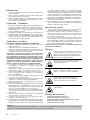
22,5
17,5
30
10
==
P1
135
A
B135
100
336
509
431
387
400 min.
P1 P1
407
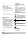
Konstruktionseigenschaften und Abmessungen
Einzelheit
der Befestigung
Modell mit Flügeldurchmesser 250 mm
Hinweise für eine korrekte Aufstellung
Mindestabstand von der Wand, Heizstabseite - Mindestabstand von der Wand, Ansaugseite
Zum seitlichen Ein- und Ausbau der Heizstäbe muß bei der
Geräteinstallation das Mindestmaß A+250 mm
eingehalten werden.
Für einen optimalen Betrieb des Motors den Mindestabstand
400 mm bei der Montage einhalten.
251 E4R 251 E4 252 G4 252 E4 253 G4 253 E4 254 G4 254 E4
251 E6R 251 E6 252 G6 252 E6 253 G6 253 E6 254 G6 254 E6
251 E8R 251 E8 252 G8 252 E8 253 G8 253 E8 254 G8 254 E8
1x250 1x250 2x250 2x250 3x250 3x250 4x250 4x250
674 774 1224 1224 1674 1674 2124 2124
380 480 930 930 1380 1380 1830 1830
12 12 12 12 12 12 12 12
12 12 12 12 12 12 12 12
1" 1" 1" 1" 1" 1" 1" 1"
14 16 24 26 33 36 42 46
Modell CGC
Motorventilatoren
n° x Ø mm
Abmessungen A
B
Innere Batterie=
Eintritt (mm)
anschlüsse Austritt (mm)
Tauwasserabfluß Ø (GAS)
Nettogewicht kg
Einzelheit der Heizstäbebefestigung
3RR 4RR
4RR (251ExR)
RBA - Hochleistungsheizstab
im Wärmeaustauscher.
RBB - Niederleistungsheizstab
im Wärmeaustauscher.
RSA - Elektrischer Heizstab in
der inneren Tropfwanne.

12
www.modine.com
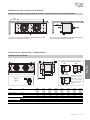
468
424
336
561
400 min.
135 135B
A
22,5
17,5
30
10
==
100
P1
P1 P1
407
Einzelheit
der Befestigung
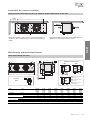
Einzelheit der Heizstäbebefestigung
RBA - Hochleistungsheizstab im Wärmeaustauscher.
RBB - Niederleistungsheizstab im Wärmeaustauscher.
RSA - Elektrischer Heizstab in der inneren Tropfwanne.
RBA2
RSA1
RBA1
RBB1
RSA1
RBA1
RBA2
RBB1
RBB2
RBA1
RBA2
RSA1
RSA1
RBB1
RBB3
RBB2
RBA1
RBA3
RBA2
RBA4
RBB1
35*F4 ED
35*F6 ED
35*F8 ED
35*E4 ED
35*E6 ED
35*E8 ED
35*E4 EDP
35*E6 EDP
35*E8 EDP
35*F4 EDP
35*F6 EDP
35*F8 EDP
35*A4 ED
35*A6 ED
35*A8 ED
35*A4 EDP
35*A6 EDP
35*A8 EDP
400 min.
135 135B
D C
A
544
499
100
382
608
P1P1
453
22,5
17,5
30
10
==
P1
Modell CGC 351 E4 351A4 352 E4 352 A4 353 F4 353A4 354 F4 354 A4 355 A4
351 E6 351A6 352 E6 352 A6 353 F6 353A6 354 F6 354 A6 355 A6
351 E8 351A8 352 E8 352 A8 353 F8 353A8 354 F8 354 A8 355 A8
Motorventilatoren n° x Ø 1x350 1x350 2x350 2x350 3x350 3x350 4x350 4x350 5x350
Abmessungen A mm 875 875 1425 1425 1975 1975 2525 2525 3075
B mm 580 580 1130 1130 1680 1680 2230 2230 2780
C mm ------1115 1115 1665
D mm ------1115 1115 1115
Eintritt (mm) 12 12 12 12 12 12 12 16 16
Austritt (mm) 12 12 12 12 (A8 16) 16 16 (A8 22) 16 (F8 22) 22 22
Tauwasserabfluß Ø (GAS) 1” 1” 1” 1” 1” 1” 1” 1” 1”
Nettogewicht kg 24 29 45 53 64 69 85 92 113
Einzelheit der Heizstäbebefestigung
Modell mit Flügeldurchmesser 350 mm
Innere Batterieanschlüsse
Modell mit Flügeldurchmesser 315 mm
RBA - Hochleistungsheizstab im Wärmeaustauscher.
RBB - Niederleistungsheizstab im Wärmeaustauscher.
RSA - Elektrischer Heizstab in der inneren Tropfwanne.
Particolare
di fissaggio
Konstruktionseigenschaften und Abmessungen
311F4 312F4 313F4 314F4
311F6 312F6 313F6 314F6
311F8 312F8 313F8 314F8
1x315 2x315 3x315 4x315
874 1424 1974 2524
580 1130 1680 2230
12 12 12 12
12 12 12 (F8 16) 16 (F8 22)
1" 1" 1" 1"
22 37 52 67
Modell CGC
Motorventilatoren
n° x Ø mm
Abmessungen A
B
Innere Batterie=
Eintritt (mm)
anschlüsse Austritt (mm)
Tauwasserabfluß Ø (GAS)
Nettogewicht kg

Deutsch
13
www.modine.com
Anschlußplan der Motorventilatoren
Achtung
die Motoren sind mit automatisch wiederaufrüstbaren Temperaturwächtern ausgestattet.
Vor Anwendung von Drehzahlreglern die Eignung für die Motoren überprüfen; nicht verträgliche Systeme können Lärm und Schäden
am Motor hervorrufen; der Hersteller lehnt jede Verantwortung für mit Drehzahlreglern ausgestattete Geräte ab.
L N
Anschlußplan der Motorventilatoren ø 250 mm
Motor Nr. 2… (eventuell) Motor Nr. 1 Abzweigdose
Kabelverbindungen
Abzweigdose
Motor Nr. 2…
(eventuell)
Motor n. 1
Stromaufnahme: 230V/1/50-60 Hz
L = braun oder grau N = blau
= gelb / grün
Stromaufnahme: 230V/1/50-60 Hz
L = braun N = blau
= gelb / grün
Anschlußplan der Motorventilatoren ø 315 - 350 mm
Motor Nr. 2… (eventuell) Motor Nr. 1 Abzweigdose
Motor Nr. 2…
(eventuell)
Motor n. 1
Modell CGC 251 E4R 251 E4 252G4 252 E4 253G4 253 E4 254G4 254 E4 311F4 312F4 313F4 314F4
251 E6R 251 E6 252G6 252 E6 253G6 253 E6 254G6 254 E6 311F6 312F6 313F6 314F6
251 E8R 251 E8 252G8 252 E8 253G8 253 E8 254G8 254 E8 311F8 312F8 313F8 314F8
Motorventilatoren 1 x 250 2 x 250 3 x 250 4 x 250 1 x 315 2 x 315 3 x 315 4 x 315
Frequenz Hz 50 60 50 60 50 60 50 60 50 60 50 60 50 60 50 60
Stromaufnahme A 0,68 - 1,36 - 2,04 - 2,72 - 0,52 0,66 1,04 1,32 1,56 1,98 2,08 2,64
Motorventilatoren W 95 - 190 - 285 - 380 - 110 148 220 296 330 444 440 592
RPM 1300 1550 1300 1550 1300 1550 1300 1550 1350 1490 1350 1490 1350 1490 1350 1490
Modello CGC 351 E4 351A4 352 E4 352 A4 353 F4 353A4 354 F4 354 A4 355 A4
351 E6 351A6 352 E6 352 A6 353 F6 353A6 354 F6 354 A6 355 A6
351 E8 351A8 352 E8 352 A8 353 F8 353A8 354 F8 354 A8 355 A8
Motori 1 x 350 2 x 350 3 x 350 4 x 350 5 x 350
Frequenza Hz 50 60 50 60 50 60 50 60 50 60
Stromaufnahme A 0,96 1,08 1,92 2,16 2,88 3,24 3,84 4,32 4,80 5,40
Motorventilatoren W 185 250 370 500 555 750 740 1000 925 1250
RPM 1420 1660 1420 1660 1420 1660 1420 1660 1420 1660
Abzweigdose

14
www.modine.com
Ausbau
1. Tauwasserabflußrohr demontieren.
2. Befestigungsschrauben “A” der Tropfwanne von der inneren
Tropfwanne losschrauben.
3. Die selbstbohrenden Schrauben “B” lockern, ohne sie jedoch
ganz abzuschrauben und die seitliche Abdeckung abnehmen.
Zusammenbau
1. Die seitliche Abdeckung mit den Schrauben “B” befestigen.
2. Tropfwanne so positionieren, daß die seitlichen Abdeckungen
innen sind und mit den Schrauben “A” befestigen.
3. Tauwasserabflußrohr montieren.
Halterungen
Seitliche
Abdeckung
Abzweigdose
Tropfwanne
Tauwasserabfluß
Innere
Tropfwanne
Lüfterblech
Ratschläge für einen korrekten Zugang zum Gerät
Anschlußplan und Leistungen der Heizstäbe
Achtung
die Motoren sind mit automatisch wiederaufrüstbaren Temperaturwächtern ausgestattet.
Vor Anwendung von Drehzahlreglern die Eignung für die Motoren überprüfen; nicht verträgliche Systeme können Lärm und Schäden
am Motor hervorrufen; der Hersteller lehnt jede Verantwortung für mit Drehzahlreglern ausgestattete Geräte ab.
Modell CGC “ED” 251E4R 251E4 252G4 252E4 253G4 253E4 254G4 254E4
ø 250 251E6R 251E6 252G6 252E6 253G6 253E6 254G6 254E6
251E8R 251E8 252G8 252E8 253G8 253E8 254G8 254E8
Rohrreihen 4 RR 4 RR 3 RR 4 RR 3 RR 4 RR 3 RR 4 RR
Gesamtleistung (W) 750 1125 2250 2250 3325 3325 4375 4375
RBA (1-2)
Hochleistungsheizstab im Wärmeaustauscher.
RBB1
Niederleistungsheizstab im Wärmeaustauscher.
RSA1
Hochleistungsheizstab in der inneren Tropfwanne.
RBB1
RBA1
RSA1
L
N
N
RBB1
RBA1
RSA1
P.E.
N
L
L
RBB1
RBA1
RSA1
L
N
N
RBB1
RBA1
RSA1
P.E.
N
L
L
RBA2
RBA1
RSA1
L
N
N
RBA2
RBA1
RSA1
P.E.
N
L
L
R
S
T
N
RBB1
RSA1
RBA1
R
S
T
N
RBB1
RSA1
RBA1
R
S
T
N
RBA2
RSA1
RBA1
N
RBB1
RBA1
RSA1
P.E.
N
R
U
RBB1
RBA1
RSA1
V
W
S
T
N
P.E.
N
R
U
V
W
S
T
RBA2
RBA1
RSA1
N
P.E.
N
R
U
V
W
S
T
CGC 251ExR CGC 252Gx
253Gx
254Gx
CGC 251Ex
252Ex
253Ex
254Ex
Modell mit Flügeldurchmesser 250 mm
ANSCHLUß 400V/3/50 Hz STANDARD

Deutsch
15
www.modine.com
Anschlußplan und Leistungen der Heizstäbe
RSA1
RBA1
RBA2
RBB1
U
V
W
N
N
W
PE
V
U
R
S
T
N
R
S
T
N
RBB1
RSA1
RBA2
RBA1
RSA1
RBA1
N
L
N
RBB1
RBA2
RBA1
RSA1
L
N
L
N
W
V
U
RBA2
RBB1
PE
Modell CGC “ED” 311F4 321F4 313F4 314F4
ø 315 311F6 321F6 313F6 314F6
311F8 321F8 313F8 314F8
Rohrreihen 5 RR 5 RR 5RR 5 RR
Gesamtleistung (W) 1750 3150 4900 6300
ANSCHLUß 400V/3/50 Hz ANSCHLUß 230V/1/50 Hz
(standard) (vorzubereiten)
Modell mit Flügeldurchmesser 315 mm
RBA (1-2) Hochleistungsheizstab im Wärmeaustauscher.
RBB1 Niederleistungsheizstab im Wärmeaustauscher.
RSA1 Hochleistungsheizstab in der inneren Tropfwanne.
Achtung
die Motoren sind mit automatisch wiederaufrüstbaren Temperaturwächtern ausgestattet.
Vor Anwendung von Drehzahlreglern die Eignung für die Motoren überprüfen; nicht verträgliche Systeme können Lärm und Schäden
am Motor hervorrufen; der Hersteller lehnt jede Verantwortung für mit Drehzahlreglern ausgestattete Geräte ab.
Modell CGC “ED” 251E4R 251E4 252G4 252E4 253G4 253E4 254G4 254E4
ø 250 251E6R 251E6 252G6 252E6 253G6 253E6 254G6 254E6
251E8R 251E8 252G8 252E8 253G8 253E8 254G8 254E8
Rohrreihen 4 RR 4 RR 3 RR 4 RR 3 RR 4 RR 3 RR 4 RR
Gesamtleistung (W) 750 1125 2250 2250 3325 3325 4375 4375
Modell mit Flügeldurchmesser 250 mm
RBB1
RBA1
RSA1
L
N
N
RBB1
RBA1
RSA1
P.E.
N
L
L
RBB1
RBA1
RSA1
L
N
N
RBB1
RBA1
RSA1
P.E.
N
L
L
RBA2
RBA1
RSA1
L
N
N
RBA2
RBA1
RSA1
P.E.
N
L
L
R
S
T
N
RBB1
RSA1
RBA1
R
S
T
N
RBB1
RSA1
RBA1
R
S
T
N
RBA2
RSA1
RBA1
N
RBB1
RBA1
RSA1
P.E.
N
R
U
RBB1
RBA1
RSA1
V
W
S
T
N
P.E.
N
R
U
V
W
S
T
RBA2
RBA1
RSA1
N
P.E.
N
R
U
V
W
S
T
CGC 251ExR CGC 252Gx
253Gx
254Gx
CGC 251Ex
252Ex
253Ex
254Ex
ANSCHLUß 230V/1/50 Hz VORZUBEREITEN
RBA (1-2)
Hochleistungsheizstab im Wärmeaustauscher.
RBB1
Niederleistungsheizstab im Wärmeaustauscher.
RSA1
Hochleistungsheizstab in der inneren Tropfwanne.

16
www.modine.com
RSA1
RBA1
RBA2
RBB1
R
S
T
N
RSA1
RBB1
RBA1
RSA1
RBA1
L
N
RBB2
RBA2
RBB1
RBA1
RSA1
RBB2
RBB2
RBA2
RBA2
RBB1
RBB2
U
V
W
N
N
W
PE
V
U
R
S
T
N
N
L
N
L
N
W
V
U
PE
ANSCHLUß 400V/3/50 Hz ANSCHLUß 230V/1/50 Hz
(standard)(vorzubereiten)
Modell mit Flügeldurchmesser 350 mm 4-5 RR strengthen
RBA (1-2) Hochleistungsheizstab im Wärmeaustauscher.
RBB (1-2) Niederleistungsheizstab im Wärmeaustauscher.
RSA1 Hochleistungsheizstab in der inneren Tropfwanne.
Anschlußplan und Leistungen der Heizstäbe
Achtung
die Motoren sind mit automatisch wiederaufrüstbaren Temperaturwächtern ausgestattet.
Vor Anwendung von Drehzahlreglern die Eignung für die Motoren überprüfen; nicht verträgliche Systeme können Lärm und Schäden
am Motor hervorrufen; der Hersteller lehnt jede Verantwortung für mit Drehzahlreglern ausgestattete Geräte ab.
Modell CGC “ED” 351 E4 352 E4 353 F4 354 F4
ø 350 351 E6 352 E6 353 F6 354 F6
351 E8 352 E8 353 F8 354 F8
Rohrreihen 4 RR 4 RR 5 RR 5 RR
Gesamtleistung (W) 2000 3600 5600 7200
R
S
N
T
RBB1
RSA1
RBA2
RBA1
L
N
RBB1
RBA2
RBA1
RSA1
RSA1
RBA1
RBA2
RBB1
U
V
W
N
N
W
PE
V
U
R
S
T
N
RSA1
RBA1
RBA2
RBB1
N
L
N
L
N
W
V
U
PE
Modell CGC “ED” 351 E4 352 E4 353 F4 354 F4
ø 350 351 E6 352 E6 353 F6 354 F6
351 E8 352 E8 353 F8 354 F8
Rohrreihen 4 RR 4 RR 5 RR 5 RR
Gesamtleistung (W) 1750 3150 4900 6300
ANSCHLUß 400V/3/50 Hz ANSCHLUß 230V/1/50 Hz
(standard) (vorzubereiten)
Modell mit Flügeldurchmesser 350 mm 4-5 RR standard
RBA (1-2) Hochleistungsheizstab im Wärmeaustauscher.
RBB1 Niederleistungsheizstab im Wärmeaustauscher.
RSA1 Hochleistungsheizstab in der inneren Tropfwanne.

Deutsch
17
www.modine.com
Anschlußplan und Leistungen der Heizstäbe
Achtung
die Motoren sind mit automatisch wiederaufrüstbaren Temperaturwächtern ausgestattet.
Vor Anwendung von Drehzahlreglern die Eignung für die Motoren überprüfen; nicht verträgliche Systeme können Lärm und Schäden
am Motor hervorrufen; der Hersteller lehnt jede Verantwortung für mit Drehzahlreglern ausgestattete Geräte ab.
RSA1
RBA1
RBA2
RBA3
RBB1
RBA4
U
V
W
N
N
W
V
U
R
S
T
N
RBB1
R
S
T
N
RBA1
RBA4
RSA1
RBA3
RBA2
RSA1
RBA1
RBA2
RBA3
N
L
N
RBB1
RBA4
RBA3
RBA2
RBA1
RSA1
L
N
L
N
W
V
U
RBB1
RBA4
PE
PE
ANSCHLUß 400V/3/50 Hz ANSCHLUß 230V/1/50 Hz
(standard) (vorzubereiten)
RBA (1-2-3-4) Hochleistungsheizstab im Wärmeaustauscher.
RBB1 Niederleistungsheizstab im Wärmeaustauscher.
RSA1 Hochleistungsheizstab in der inneren Tropfwanne.
Modell mit Flügeldurchmesser 350 mm 6RR strengthen
Modell CGC “ED” 351 A4 352 A4 353 A4 354 A4 355 A4
ø 350 351 A6 352 A6 353 A6 354 A6 355 A6
351 A8 352 A8 353 A8 354 A8 355 A8
Rohrreihen 6 RR 6 RR 6 RR 6 RR 6 RR
Gesamtleistung (W) 2750 4950 7700 9900 12100
RSA1
RBA1
RBB1
RBA2
RBB3
RBB2
U
V
W
N
N
W
V
U
R
S
T
N
RBB3
R
S
T
N
RBB1
RBA2
RSA1
RBB2
RBA1
RSA1
RBA1
RBB1
RBA2
RBB3
RBB2
RSA1
RBA1
RBB1
RBA2
RBB3
RBB2
R
S
T
RBB3
RBB1
RBA2
RSA1
RBB2
RBA1
U
V
W
N
W
V
U
R
S
T
N
L
N
RBB3
RBA2
RBB2
RBA1
RBB1
RSA1
L
N
L
N
W
V
U
PE
PE
PE
ANSCHLUß 400V/3/50 Hz ANSCHLUß 230V/3/50 Hz ANSCHLUß 230V/1/50 Hz
(standard)(vorzubereiten)(vorzubereiten)
RBA (1-2) Hochleistungsheizstab im Wärmeaustauscher.
RBB (1-2-3) Niederleistungsheizstab im Wärmeaustauscher.
RSA1 Hochleistungsheizstab in der inneren Tropfwanne.
Modell mit Flügeldurchmesser 350 mm 6RR standard
Modell CGC “ED” 351 A4 352 A4 353 A4 354 A4 355 A4
ø 350 351 A6 352 A6 353 A6 354 A6 355 A6
351 A8 352 A8 353 A8 354 A8 355 A8
Rohrreihen 6 RR 6 RR 6 RR 6 RR 6 RR
Gesamtleistung (W) 2250 4050 6300 8100 9900

Caution
Before carrying out maintenance on unit, make sure that the electric feed is disconnegced from main power source: the electric parts
may be connegced to an automatic control system.
Important
1. Keep this manual for the lifespan of model.
2. Read technical manual carefully before installation and prior to
any intervention on model.
3. Use model exclusively for the purpose for which it has been
designed; misuse exempts manufacturer from any responsibility.
Inspection - Transport
1. Upon delivery immediately examine condition of model; should
damages be detegced promptly notify forwarder.
2. During transport of model it is necessary to avoid pressure on
packaging and it must be kept in upright position as indicated
on package.
3. Unpack model as close as possible to installation site. When
packaging is removed from model, care must be exercised in
order to avoid damage to parts.
4. In order to avoid injury from the model's sharp edges (e.g. fins)
during installation and positioning of model use of special pro-
tective gloves is recommended.
For a proper installation
1. Verify structural bearing of ceiling in relation to the weight of
the unit.
2. Verify that the unit is installed horizontally.
3. Ensure an adequate free space (approx. 30% of the inner
room volume) to allow a proper intake and exhaust air circu-
lation.
Particular conditions of installation or operation such as low
or beamed rooms, overstorage, obstrugced intake and exhau-
st air circulation and improper ice build-up due to excessive
entry of humidity in room may negatively affect the stated
performance and may cause defects.
Standard models may not be suitable for blast freezer and
chill room application.
4. The models are equipped with axial fan motors, therefore not
suitable for duct ventilation systems and cannot sustain extra
static air pressure drops.
5. Verify that the operating conditions (temperatures and pressu-
res) are in accordance to those of project.
6. Care must be exercised during the connecting phase in order
to avoid possible distortion of the capillary tubes and shifting of
the distributor.
7. In the case of more than one model installed at close range it is
advisable to avoid alternate defrostings.
8. Fit the appropriate siphons on the condensate drain connec-
tions and assess their efficiency in all working temperatures.
9. Avoid installation of the units next to the cold-room doors.
10. Place the end of defrost temperature feeler in the coldest areas
of the coil, i.e. the areas that tend to freeze more (at the end of
the cycle the unit should be completely ice-free).
The position of this device cannot be defined in advance,
because it varies in accordance to the type cold room and type
of installation.
11. Verify that the electrical feed network is in accordance to the
electrical features of model.
12. Ensure that all the electric wiring is in compliance with the stan-
dards in force.
13. The units are predisposed for ground wiring connection.
The unit installer and/or plant operator must ensure the presen-
ce of an efficient earthing connection to protect against indirect
electric contacts.
The electric heating elements eventually used for defrosting
are housed in junction boxes made of thermoplastic material,
with protection rating IP 54.
Upon request, models can be supplied with coils, defrosting
units and fan motors different from the standard ones.
14. The protective film is to be removed from model upon comple-
tion of installation.
15. Access to model, for any type of intervention, is reserved to
qualified personnel as per regulations in force.
General Maintenance
1. Periodically inspect fastenings, electrical connections and con-
nections to cooling installation.
2. It is necessary to arrange periodical cleaning of unit in order to
avoid deposits of toxic substances. Use of mild detergent is
recommended; avoid use of solvents, aggressive, abrasive or
ammonia-based agents.
3. When replacing electric heaters take particular care during
installation in order to avoid damage to the vulcanization; cor-
rectly reset wiring and existing fastening systems to avoid pos-
sible movement during operation.
The above-mentioned operations are to be carried out by qua-
lified personnel only.
Hazards / Risks
1. Electric shock. The model is equipped with fan
motors and electric defrost heaters. The supply
voltage is 400 V AC. It is important to use
electrical safety systems that are in compliance to
the regulations in force.
2. Burns. The surface of the electric defrost heaters
can reach the temperature of 350 ° C.
3. Cuts. The heat exchanger is made with fins with
sharp edges and the casing is made of sheet
metal parts.
4. Parts in motion. The model is equipped with fan
motors fitted with external protection.
5. Crushing. The weight of unit may exceed 500 kg.
Reference standards
- MACHINES DIRECTIVE 2006/42/EC
- LOW-VOLTAGE DIRECTIVE 2014/35/UE
- ELECTROMAGNETIC COMPATIBILITY DIR. 2014/30/UE
- PED DIRECTIVE 2014/68/UE
- ERP DIRECTIVE 2009/125/EC
18
www.modine.com
La pagina si sta caricando...
La pagina si sta caricando...
La pagina si sta caricando...
La pagina si sta caricando...
La pagina si sta caricando...
La pagina si sta caricando...
La pagina si sta caricando...
La pagina si sta caricando...
La pagina si sta caricando...
La pagina si sta caricando...
La pagina si sta caricando...
La pagina si sta caricando...
La pagina si sta caricando...
La pagina si sta caricando...
La pagina si sta caricando...
La pagina si sta caricando...
La pagina si sta caricando...
La pagina si sta caricando...
La pagina si sta caricando...
La pagina si sta caricando...
La pagina si sta caricando...
La pagina si sta caricando...
La pagina si sta caricando...
La pagina si sta caricando...
La pagina si sta caricando...
La pagina si sta caricando...
La pagina si sta caricando...
La pagina si sta caricando...
La pagina si sta caricando...
La pagina si sta caricando...
La pagina si sta caricando...
La pagina si sta caricando...
La pagina si sta caricando...
La pagina si sta caricando...
La pagina si sta caricando...
La pagina si sta caricando...
-
 1
1
-
 2
2
-
 3
3
-
 4
4
-
 5
5
-
 6
6
-
 7
7
-
 8
8
-
 9
9
-
 10
10
-
 11
11
-
 12
12
-
 13
13
-
 14
14
-
 15
15
-
 16
16
-
 17
17
-
 18
18
-
 19
19
-
 20
20
-
 21
21
-
 22
22
-
 23
23
-
 24
24
-
 25
25
-
 26
26
-
 27
27
-
 28
28
-
 29
29
-
 30
30
-
 31
31
-
 32
32
-
 33
33
-
 34
34
-
 35
35
-
 36
36
-
 37
37
-
 38
38
-
 39
39
-
 40
40
-
 41
41
-
 42
42
-
 43
43
-
 44
44
-
 45
45
-
 46
46
-
 47
47
-
 48
48
-
 49
49
-
 50
50
-
 51
51
-
 52
52
-
 53
53
-
 54
54
-
 55
55
-
 56
56


