
FOT000077 REV.1.0
WB-OP10 / WB-OP12 / WB-OP15
ISTRUZIONI DI UTILIZZO WB-OP10 / WB-OP12 / WB-OP15
WB-OP10 / WB-OP12 /WB-OP15 INSTRUCTIONS
Accessorio
Accessory
Prodotto
Product
WB-OP10 OPERA 10
WB-OP10 / WB-OP12 /WB-OP15--> Staffe a muro compatibili con gli speaker OPERA indicati in
tabella.
WB-OP10 / WB-OP12 / WB-OP15--> Wall brackets suitable for OPERA speakers as described in
the table.
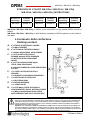
1.Contenuto della confezione
Packing content
A - n°1 STAFFA DI SOSTEGNO A MURO
n°1 WALL BRACKET
B - n°1 VITE M8x16 TESTA ESAGONALE
n°1 M8x16 HEXAGONAL HEAD SCREW
C - n°2 VITI DI FISSAGGIO DELLO
SPEAKER M10x20 TESTA BOMBATA
n°2 BUTTON HEAD HEXAGONAL
SOCKET
D - n°2 VITI DI ANGOLAZIONE M5x8
TESTA CAVA ESAGONALE
n°2 M5x8 CYLINDRICAL HEAD HEXAGONAL
SOCKET
E - n°1 STAFFA DI FISSAGGIO DELLO
SPEAKER
n°1 BRACKET FOR SPEAKER MOUNTING
F - n°1 NOTTOLINO DI FISSAGGIO
n°1 BLOCKING PAWL
G - n°1 PERNO INFERIORE
n°1 LOWER PIVOT
H - n°1 VITE M8x75 TESTA ESAGONALE
CON RONDELLE E DADO AUTOBLOCCANTE
n°1 M8x75 HEXAGONAL HEAD SCREW
WITH WASHERS AND SELF-LOCKING NUT
Accessorio
Accessory
Prodotto
Product
WB-OP12 OPERA 12
Accessorio
Accessory
Prodotto
Product
WB-OP15 OPERA 15
ATTENZIONE: WB-OP10, WB-OP12, WB-OP15 devono essere utilizzati solo da personale qualicato!
Assicurarsi che l’installazione sia posizionata in modo stabile e sicuro per scongiurare ogni condizione di
pericolo per persone, animali e/o cose. L’utilizzatore è tenuto a vericare le regolamentazioni e le leggi
cogenti in materia di sicurezza nel Paese in cui si utilizza il prodotto. Installare il prodotto attenendosi a
quanto illustrato in queste istruzioni.
WARNING: For installation of WB-OP10, WB-OP12 and WB-OP15 use only specialist personnel! Make sure
that the installation is positioned in a stable and secure way in order to avoid any dangerous conditions
for people, animals and/or objects. It is mandatory to follow the safety law and regulations of the Country
in which the equipment is installed. Install the product as described in these instructions.

WB-OP10 / WB-OP12 / WB-OP15
FOT000077 REV.1.0
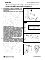
2. Preassemblaggio ed esempio di installazione a muro
2. Preassembly and wall-mounting example
a - Preassemblare la staffa (A) utilizzando la vite
(H) come mostrato a lato per ssare il perno
inferiore (G).
Il montaggio successivo deve essere effettuato
da due persone e può essere necessario l’utiliz-
zo di una scala.
Preassemble the (A) bracket using the (H) screw
to mount the lower pivot (G).
Two persons are needed for the further instal-
lation and a ladder could be possibly used.
b - Vericare che la parete su cui si effettua l’in-
stallazione sia adatta al ssaggio a muro degli
speaker OPERA, per consistenza, forabilità e
caratteristiche statiche. Utilizzare i fori indicati
per ssare le staffe (A) con opportuni mezzi
meccanici (non inclusi) al muro. E’ qui illustrata
l’installazione verticale (massima inclinazione
verso il basso dello speaker: 10°), ma è am-
messa anche quella orizzontale, oltre ad altre
illustrate nel paragrafo 3.
Check that the wall in which you want to make
the installation is appropiate to wall-mount of
OPERA speakers (strenght of the wall, possi-
bility to drill it, static characteristics). Use the
holes shown in the side picture to mount the
(A) bracket on the wall, fastening it with ap-
propiate mechanical hardware (not supplied).
It is here illustrated the vertical conguration
(maximum tilt angle: 10°), but it is admitted
also the horizontal one, among other kinds
described in section 3.
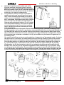
c - Allineare la staffa di ssaggio (E) sotto la staffa
ssata a muro (A), come mostrato nella gura a
anco. Inserire quindi il nottolino (F) allineato
centrando le 2 staffe nella posizione indicata e
avvitare la vite (B). Non serrare troppo la vite
per permettere le successive regolazioni.
Align the (E) bracket under the wall-mounted
(A) one, as shown in the side picture.
Insert the (F) pawl aligning it and centering the
two brackets in the position shown and screw
the (B) screw. Don’t tighten too much the
screw to allow the further settings.
d - Inserire lo speaker sul perno inferiore (G),
come da gura a lato.
Insert the speaker in the lower pivot (G), as
shown in the side picture.

FOT000077 REV.1.0
WB-OP10 / WB-OP12 / WB-OP15
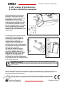
e - Allineare lo speaker avvicinandolo alla staffa
(E) come mostrato. Avvitarne quindi il top alla
staffa con le 2 viti (C) utilizzando gli appositi fori.
Move the speaker closer to the (E) bracket aligning
it as shown in the side pictures. Screw the bracket
to the top of it using the related holes.
f - La regolazione sull’asse verticale è possibile in
modo continuo fra 10° verso il basso e 3° verso
l’alto. Viene effettuata allentando la vite (B), fa-
cendo scorrere la staffa (E) a cui è ssato lo spea-
ker e riavvitando. Nella gura sotto sono riportati
alcuni esempi con riferimenti di angolazione. E’
illustrata una posizione di sblocco in cui il nottoli-
no si libera dalla staffa (E), rilasciando lo speaker
ad un’inclinazione di 4,5° verso l’alto. In questo
caso il cabinet deve essere sostenuto per l’even-
tuale smontaggio.
La regolazione sull’asse orizzontale avviene allentando la vite (B) e ruotando la staffa (E) a cui è
ssato lo speaker. A 0° verticali, in particolare, sono possibili passi di 22,5° orizzontali ssabili con
una vite (D) sulla staffa (A). La seconda vite (D) viene ssata in una posizione libera sulla staffa
(E), con funzione di blocco di sicurezza, come mostrato. Agire allentando o stringendo la vite (B)
ed eventualmente avvitando o svitando le viti (D) per modicare a piacimento le regolazioni su
entrambi gli assi.
The vertical axis tilting can be set continuosly from 3° upward to 10° downward angles. To obtain
the desired tilt it is necessary to release the (B) screw and let the bracket (E) slide to the related
position and screw it. In the picture below some positions are illustrated with angle references.
An unlocking position, in which the pawl is freed from the (E) bracket, releasing the speaker at
4,5° upward tilt angle, is illustrated. In this case the cabinet has to be holded for the possible
dissassembly. On the horizontal axis, the tilt is set releasing the (B) screw and rotating the (E)
bracket. At 0°, the user can set horizontal regulation with a resolution of 22,5° as shown, using
one (D) screw on the (A) bracket. The second (D) screw may be screwed in a further free position
on the (E) bracket, with safety blocking function as shown. Tighten and release the (B) screw and
screw and unscrew the (D) screws to adjust the settings to the preferred value on both the axis.

WB-OP10 / WB-OP12 / WB-OP15
FOT000077 REV.1.0
Features, specication and appearance of products are subject to change without notice. dBTechnologies reserves the
right to make changes or improvements in design or mafacturing without assuming any obligation to change or
improve products previously manufactured.
A.E.B. Industriale Srl V ia Brodolini, 8 Località Crespellano 40053 VALSAMOGGIA BOLOGNA (ITALIA)
Tel +39 051 969870 Fax +39 051 969725 www.dbtechnologies.com info@dbtechnologies-aeb.com
3.Altri esempi di installazione
3.Further installation examples
Nell’installazione orizzontale la
staffa (E) è fatta scorrere nella
posizione a 0° (vedi la sezione 2),
regolando poi con le viti (C)
l’angolazione, con passi di 22,5°
come mostrato nella gura a lato.
In horizontal installation the (E)
bracket is positioned to o° (see the
section 2) and the (C) screws are
used to set the tilt angle with a
resolution of 22,5°, as shown in the
side picture.
La staffa permette anche l’utilizzo
di aliscaff (non inclusi) con cui
montare gli speaker OPERA su
un’americana. Per questa
congurazione utilizzare i fori
indicati a lato, l’installazione
può poi avvenire sia in orizzontale
che verticale, secondo le speciche
della struttura esistente.
The bracket allows the use of
aliscaff hooks (not supplied) to
mount the OPERA speakers on
stage lighting truss. Use the holes
indicated in the side picture to
congure your installation, in
horizontal or vertical conguration,
in accordance with the characteristics
of the stage structure.
ATTENZIONE: Al ne dell’utilizzo in sicurezza dell’accessorio, vericarne periodicamente funzionalità e
integrità prima dell’utilizzo.
WARNING: Check periodically the integrity and functionality of this optional equipment before the use, for
a safe installation.
-
 1
1
-
 2
2
-
 3
3
-
 4
4


dBTechnologies WB OP10 Manuale del proprietario
- Tipo
- Manuale del proprietario
in altre lingue
Documenti correlati
-
dBTechnologies OPERA 15 Manuale del proprietario
-
dBTechnologies WB-VIOX205H Manuale del proprietario
-
-
-
-
-
-
Altri documenti
-
LG ARUN050GSL0 Manuale del proprietario
-
-
LG ARUN080BSS0.AWGBLAT Guida d'installazione
-
Zenoah BK5300DL Manuale utente
-
LG ARUN050GSS0 Manuale del proprietario
-
 Outsunny 840-221BG Assembly Instructions
-
LG ZRUN060GSS0 Manuale del proprietario
-
LG ARUB060GSS4 Manuale del proprietario
-
LG ARUM080LTE5 Manuale del proprietario
