
EN
English - Instruction manual
IT
Italiano - Manuale di istruzioni
FR
Français - Manuel d’instructions
DE
Deutsch - Bedienungsanleitung
RU
Русский - Руководство по эксплуатации
PT
Português - Manual de instruções
KO
한국어 - 지침 설명서
ENGLISH
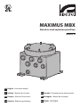
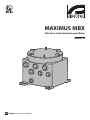
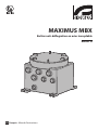
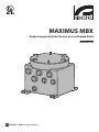
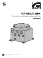
MAXIMUS MBX
Stainless steel explosion-proof box
Manual a


EN
English - Instruction manual
ENGLISH
MAXIMUS MBX
Stainless steel explosion-proof box
Manual a


Instruction manual - English - EN
3MNVCMBX_1929_EN
Contents
ENGLISH 1
1 About this manual ....................................................................................................................5
1.1 Typographical conventions ................................................................................................................................................ 5
Underlined titles ..........................................................................................................................5
2 Notes on copyright and information on trademarks .............................................................5
3 Safety rules................................................................................................................................5
4 Identication .............................................................................................................................7
4.1 Product description and type designation ................................................................................................................... 7
4.2 Product Overview................................................................................................................................................................... 7
4.3 Range of use ............................................................................................................................................................................. 7
4.4 Specic use conditions ......................................................................................................................................................... 7
4.5 Gas Group, Dust Group and Temperatures ................................................................................................................... 8
4.6 Characteristics of installable devices............................................................................................................................... 8
4.7 Cable entry ................................................................................................................................................................................ 8
4.8 Product marking ..................................................................................................................................................................... 9
4.9 For UL/CSA standard reference only. .............................................................................................................................10
5 Preparing the product for use ...............................................................................................12
5.1 Safety precautions before use .........................................................................................................................................12
5.2 Unpacking ...............................................................................................................................................................................12
5.3 Contents ..................................................................................................................................................................................12
5.4 Safely disposing of packaging material .......................................................................................................................12
5.5 Product opening ................................................................................................................................................................... 13
5.6 Ground connection .............................................................................................................................................................13
5.6.1 Earthing equipotential connection ................................................................................................................................................. 13
5.6.2 Connection of the safety earthing...................................................................................................................................................13
5.7 Product closure .....................................................................................................................................................................14
6 Maintenance ...........................................................................................................................14
6.1 Replacement of the cover gasket ................................................................................................................................... 14
7 Cleaning ..................................................................................................................................15
7.1 Cleaning the product .......................................................................................................................................................... 15
8 Information on disposal and recycling .................................................................................15
9 Technical data .........................................................................................................................16
9.1 Mechanical ..............................................................................................................................................................................16
9.2 Environment ...........................................................................................................................................................................16
9.3 Certications .......................................................................................................................................................................... 16
9.4 Certications - Explosion-proof applications ............................................................................................................. 16
10 Technical drawings ...............................................................................................................17

EN - English - Instruction manual
4 MNVCMBX_1929_EN

Instruction manual - English - EN
5MNVCMBX_1929_EN
1 About this manual
Read all the documentation supplied carefully before
installing and using this unit. Keep this manual
and use instructions of the box within reach for
subsequent consultation.
1.1 Typographical conventions
DANGER!
Explosion hazard.
Read carefully to avoid danger of explosion.
DANGER!
High level hazard.
Risk of electric shock. Disconnect the
power supply before proceeding with any
operation, unless indicated otherwise.
CAUTION!
Medium level hazard.
This operation is very important for the
system to function properly. Please read
the procedure described very carefully and
carry it out as instructed.
INFO
Description of system specications.
We recommend reading this part carefully
in order to understand the subsequent
stages.
Underlined titles
Information is subject to certications.
2 Notes on copyright and
information on trademarks
The mentioned names of products or companies are
trademarks or registered trademarks.
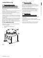
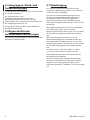
3 Safety rules
DANGER!
Explosion hazard.
Read carefully to avoid danger of explosion.
• Installation and maintenance of the appliance
must be carried out by specialist technical sta in
compliance with the applicable reference code
EN/IEC 60079-14, EN/IEC 60079-17 and national
standards.
• Installation should be carried out using adequate
tools. The location in which the device is installed
may require use of specic tools.
• CAUTION! The external equipotential connections
must be set up through the eyelet on the outside
of the product. Do not use as a protective terminal.
Use cables with a minimum section equal to: 4mm²
(11AWG).
• The equipotential connection is mandatory to
avoid the risk of ignition of products installed in
potentially explosive environments.
• Do not open the device when powered and in
explosive atmosphere.
• Make all connections, installation and maintenance
work in a non-explosive atmosphere.
• The temperature of the surfaces of the device
is increased by exposure to direct sunlight.
The surface temperature class of the device
was determined only with ambient ambient
temperature, without taking into consideration
direct sunlight.
• Make sure that the unit and other components of
the installation are closed so that it is impossible to
come into contact with live parts.
• Ensure that the sealing of cable entry systems (if
any) has been performed properly and the time of
glue hardening has been observed.

EN - English - Instruction manual
6 MNVCMBX_1929_EN
DANGER!
High level hazard.
Risk of electric shock. Disconnect the
power supply before proceeding with any
operation, unless indicated otherwise.
• Before starting any operation, make sure the
power supply is disconnected.
• A power disconnect device must be included
in the electrical installation, and it must be very
quickly recognizable and operated if needed.
• Be careful not to use cables that seem worn or old.
• This equipment is not suitable for use in locations
where children are likely to be present.
CAUTION!
Medium level hazard.
This operation is very important for the
system to function properly. Please read
the procedure described very carefully and
carry it out as instructed.
• Make sure the appliance is securely anchored
before supplying power.
• Any change that is not expressly approved by the
manufacturer will invalidate the guarantee.
• For technical services, consult only and exclusively
authorized technicians.
• Comply with all the national standards during the
device installation.
• The product can be installed in any position.
• All disconnected wires must be electrically
isolated.
• The manufacturer declines all liability for damage
to any of the apparatus mentioned in this
handbook, when resulting from tampering, use of
non-original spare parts, installation, maintenance
and repairs performed by non-authorised, non-
skilled personnel.
• This product must only be repaired by suitably
trained personnel or under the supervision of
VIDEOTEC personnel in accordance with the
foreseen terms and conditions: IEC/EN60079-19.
• Whenever replacing the parts as indicated,
always use VIDEOTEC original spare parts and
meticulously follow the maintenance instructions
supplied with every spare parts kit.
INFO
Description of system specications.
We recommend reading this part carefully
in order to understand the subsequent
stages.
• For handling there are no particular instructions.
It is recommended, to assigned sta, to carry out
operation observing the common rules of accident
prevention.
• Make sure that all precautions for personal safety
have been taken.
• Before proceeding with installation, check the
supplied material to make sure it corresponds
to the order specication by examining the
identication labels.
• Equipment intended for installation in Restricted
Access Location performed by specialist technical
sta.
• Since the user is responsible for choosing the
surface to which the unit is to be anchored, we
do not supply the xing devices for attaching the
unit rmly to the particular surface. The installer is
responsible for choosing xing devices suitable for
the specic purpose on hand. Use methods and
materials capable of supporting at least 4 times the
weight of the device. Remember to use screws no
less than M8 (ISO261) or equivalent.
• The manufacturer declines all responsibility
for any damage caused by an improper use
of the appliances mentioned in this manual.
Furthermore, the manufacturer reserves the right
to modify its contents without any prior notice.
The documentation contained in this manual has
been collected and veried with great care. The
manufacturer, however, cannot take any liability
for its use. The same thing can be said for any
person or company involved in the creation and
production of this manual.
• Contact the manufacturer for information on the
dimensions of the ameproof joint.
• For all maintenance interventions, we recommend
you return the product to the laboratory that will
perform all required operations.

Instruction manual - English - EN
7MNVCMBX_1929_EN
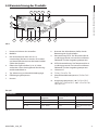
4 Identication
4.1 Product description and type
designation
MAXIMUS MBX is a box for installation in potentially
explosive atmospheres.
MAXIMUS MBX is composed of a body and cover in
stainless steel AISI 316L casting.
The surface treatments further increase its resistance
to corrosion.
MAXIMUS MBX is equipped with NPT or metric type
threaded cable inputs depending on the model.
MAXIMUS MBX has an IP66/IP68/IP69 level of
protection and can be installed in environments with
temperatures from -40°C to 80°C (check the marking
for each of the available models).
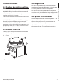
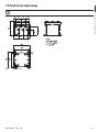
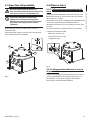
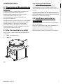
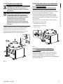
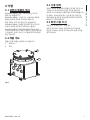
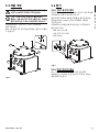
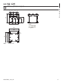
4.2 Product Overview
The main parts of the product are illustrated below.
1. Explosion-proof box.
2. Cover.
02
01
Fig. 1
4.3 Range of use
The unit is designed for use in a xed location, for
surveillance of areas classied as zone 1-21 and zone
2-22 with potentially explosive atmospheres.
The unit has been built and certied in compliance
with directive 2014/34/UE and with the international
standards IECEX, which dene its range of application
and minimum safety requirements.
4.4 Specic use conditions
Ambient temperature and Surface temperature – see
instructions.
Contact the manufacturer for information on the
dimensions of the ameproof joint.
Care shall be taken to prevent accumulation of
electrostatic charges. See installation instructions.

EN - English - Instruction manual
8 MNVCMBX_1929_EN
4.5 Gas Group, Dust Group and
Temperatures
The device is certied for the IIC group (Gas) and the
IIIC group (dust).
The temperature class, the maximum surface
temperature and the temperature of the cable entry
depend on the features of the installable devices
(Watt) and on the ambient temperature.
These features are specied for each model in manual
B.
4.6 Characteristics of installable
devices
All the internal components must be installed inside
by the manufacturer.
4.7 Cable entry
The product is supplied with plastic caps for cable
entry protection. They cannot be used for installation.
Unused cable entries shall be closed o using
blanking devices Ex certied, as appropriate, with
protection type "db" and "tb" suitable for the
conditions of use and installed correctly..
All cable glands shall be Ex certied, as appropriate,
with protection type "db" and "tb", suitable for the
conditions of use and installed correctly..
When conduit is used, a suitable Ex certied stopping
box shall be used, as appropriate, with protection
type "db" and "tb", suitable for the conditions of use
and installed correctly.
The stopping box must be tted within 50mm
(1.97in) from the enclosure entry.
The cable input temperatures are specied in the
marking.
To maintain the IP level of product use cable glands
with appropriate IP level and apply to threads a
sealant compliant with standard IEC/EN60079-14.

Instruction manual - English - EN
9MNVCMBX_1929_EN
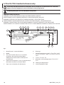
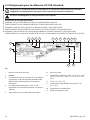
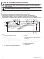
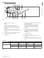
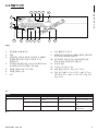
4.8 Product marking
1
7
9
11
52 3
10
86
4
12
1314
12
13
Fig. 2
1. Manufacturer’s name and address.
2. Model.
3. The serial number consists in 12 numeric
characters, the second and third digits
dene the last two numbers of the year of
manufacture.
4. Electrical characteristics (V, Hz, A). Not present, if
the device installed is a terminal block.
5. Type, size and number of cable entries.
6. Cable input temperature.
7. Warnings.
8. Number of the accredited body providing
quality evaluation.
9. ATEX marking. The Class temperature depends
on the electronics installed inside and the
ambient temperature.
10. Marking IECEX. The Class temperature depends
on the electronics installed inside and the
ambient temperature.
11. IP protection degree.
12. T Class (Tx or Tx...Tx).
13. Maximum surface temperature (Tx°C or Tx°C...
Tx°C).
14. Ambient temperature (-40°C ≤ Ta ≤+TX°C, -40°C
≤ Ta ≤ TX°C or TX°C, -40°C ≤ Ta ≤ TX°C or TX°C or
TX°C).
Example:
EXAMPLE DATA
Watt T Class Maximum surface
temperature
Cable entry tempe-
rature
Ambient temperature
16 T4 T135°C 87.4°C -40°C ≤ Ta ≤ 80°C
T6…T5 T85°C…T100°C 77.4°C -40°C ≤ Ta ≤ 60°C or 70°C
T6…T4 T85°C...T135°C 87.4°C -40°C ≤ Ta ≤ 60°C or 70°C
or 80°C
Tab. 1

EN - English - Instruction manual
10 MNVCMBX_1929_EN
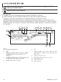
4.9 For UL/CSA standard reference only.
In the USA, the National Electrical Code (NEC) and in Canada the Canadian Electrical Code (CEC)
apply to electrical equipment used on hazardous industrial premises.
The ameproof joints are not intended to be repaired.
Important safety instructions
WARNING: DO NOT OPEN WHEN AN EXPLOSIVE ATMOSPHERE IS PRESENT.
AVERTISSEMENT: NE PAS OUVRIR EN PRÈSENCE D'UNE ATMOSPHÉRE EXPLOSIVE.
WARNING: POTENTIAL ELECTROSTATIC CHARGING HAZARD - SEE INSTRUCTIONS.
AVERTISSEMENT: DANGER POTENTIEL DE CHARGES ÈLECTROSTATIQUES - VOIR INSTRUCTIONS.
WARNING: CONDUITS MUST BE SEALED WITHIN 50MM OF CONDUIT ENTRANCE TO THE ENCLOSURE.
AVERTISSEMENT: LES CONDUITS DOIVENT ÊTRE SCELLES À DANS 50MM DE L’ENTRÉE DU CONDUIT DU CAISSON.
1
6
52 3
7 8
9
4
10
9
9
8
8
11
Fig. 3
1. Manufacturer’s name and address.
2. Model.
3. The serial number consists in 12 numeric
characters, the second and third digits
dene the last two numbers of the year of
manufacture.
4. Electrical characteristics (V, Hz, A). Not present, if
the device installed is a terminal block.
5. Type, size and number of cable entries.
6. Warnings.
7. Ambient temperature (-40°C ≤ Ta ≤+TX°C, -40°C
≤ Ta ≤ TX°C or TX°C, -40°C ≤ Ta ≤ TX°C or TX°C or
TX°C).
8. T Class (Tx or Tx...Tx).
9. Maximum surface temperature (Tx°C or Tx°C...
Tx°C).
10. Cable input temperature.
11. Level of protection Type.

Instruction manual - English - EN
11MNVCMBX_1929_EN
Connections
The choice of connection must comply with local legislation in force.
Cable glands:select a cable gland in compliance with UL2225 with the following protection AEx d IIC and C22.2
with the following protection Ex d IIC in compliance with the marking of the product.
Conduit:it is necessary to install a sealing device within 50mm of the product input when the conduit is used.
Regulation references:
UL 60079-0, 7th Edition, Explosive atmospheres - Part 0: Equipment – General requirements
UL 60079-1, 7th Edition, Explosive Atmospheres - Part 1: Equipment Protection by Flameproof Enclosures “d”
UL 60079-31, 2nd Edition, Explosive Atmospheres - Part 31: Equipment Dust Ignition Protection by Enclosure “t”
CSA C22.2 No. 60079-0:15, Explosive atmospheres - Part 0: Equipment - General requirements
CSA C22.2 No. 60079-1:16, Explosive Atmospheres - Part 1: Equipment Protection by Flameproof Enclosures “d”
CSA C22.2 No. 60079-31:15, Explosive Atmospheres - Part 31: Equipment Dust Ignition Protection by Enclosure “t”

EN - English - Instruction manual
12 MNVCMBX_1929_EN
5 Preparing the product for
use
Before carrying out any type of
intervention, read the Safety standards
chapter carefully in the product manual.
5.1 Safety precautions before use
If the device comes into contact with harsh
substances, it is the responsibility of the user to take
suitable precautions to prevent damage and not
compromise the type of protection.
• Aggressive substances: Acidic liquids or gases
that may attack metals, or solvents that may aect
polymeric materials.
• Suitable precautions: Regular checks as part
of routine inspections or establishing from the
material’s data sheet that it is resistant to specic
chemicals.
It is the responsibility of the end users to make sure
that the materials used to build the product are
suitable for the intended installation site. If in doubt,
contact the manufacturer.
5.2 Unpacking
When the product is delivered, make sure that the
package is intact and that there are no signs that it
has been dropped or scratched.
If there are obvious signs of damage, contact the
supplier immediately.
When returning a faulty product we recommend
using the original packaging for shipping.
Keep the packaging in case you need to send the
product for repairs.
5.3 Contents
Check the contents to make sure they correspond
with the list of materials as below:
• Explosion-proof box
• O-ring replacement part kit, hexagon socket set
screws
• Instruction manuals
5.4 Safely disposing of packaging
material
The packaging material can all be recycled. The
installer technician will be responsible for separating
the material for disposal, and in any case for
compliance with the legislation in force where the
device is to be used.

Instruction manual - English - EN
13MNVCMBX_1929_EN
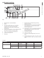
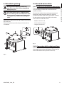
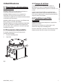
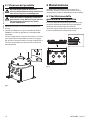
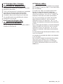
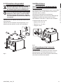
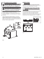
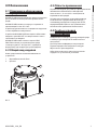
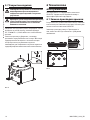
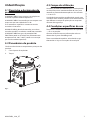
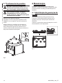
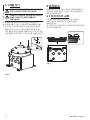
5.5 Product opening
During product opening and closing
operations, be careful not to damage the
ameproof joint.
The safety grub screw is used to prevent
the unscrewing of the threaded cover from
the connection compartment. Remove the
safety grub screw before unscrewing the
cover.
Remove the safety grub screw (01) before unscrewing
the cover (02).
Remove all plastic caps (03), they can't be used on
installation.
01
02
03
Fig. 4
5.6 Ground connection
5.6.1 Earthing equipotential connection
The equipotential connection must be carried out
using an external cable with a minimum 4mm²
section (11AWG).
Connect the cable for the earthing equipotential
connection with the eyelet terminal supplied
(suitable for cables with 4mm² up to 6mm² section).
Fix the eyelet using the screw (M5) and washer.
Characteristics of the M5 screw:
• Material: A4 Class 70
• Screw head: ISO 4762
• Length: 8mm (0.3in)
Fig. 5
5.6.2 Connection of the safety earthing
Electrically connect the safety earthing cable in one
of the holes prepared on the bottom of the box (for
more information to the product manual B).

EN - English - Instruction manual
14 MNVCMBX_1929_EN
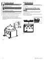
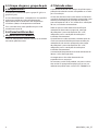
5.7 Product closure
During product opening and closing
operations, be careful not to damage the
ameproof joint.
Before closing the cover, check the O-ring
gasket. If the sealing is damaged replace it
with the one supplied.
Verify that there is no dirt or debris.
Lubricate the threads with grease compliant with IEC/
EN60079-14 to facilitate screwing the cover on.
Screw the cover and ensure there is not space
between the cover and the body of the box.
Fastening the safety grub screw is mandatory to
complete product closure and prevent the unwanted
unscrewing.
Fig. 6
6 Maintenance
When contacting VIDEOTEC for assistance please
provide the serial number and the identication code
of the model.
6.1 Replacement of the cover
gasket
In the event of o-ring gasket deterioration replace
it using the gasket supplied. Use only VIDEOTEC
original spare parts.
Replace the gasket being careful to insert it correctly
into its specic position.
Fig. 7

Instruction manual - English - EN
15MNVCMBX_1929_EN
7 Cleaning
Frequency will depend on the type of
environment in which the product is used.
7.1 Cleaning the product
The cleaning of the product should be
carried out according to the instructions
in this chapter in order to prevent
accumulation of electrostatic charges.
The outside surface of the product must
never be covered in more than 5 mm of
dust.
The device should be cleaned using a damp cloth;
compressed air must not be used.
8 Information on disposal
and recycling
The European Directive 2012/19/EU on Waste
Electrical and Electronic Equipment (WEEE) mandates
that these devices should not be disposed of in the
normal ow of municipal solid waste, but they should
be collected separately in order to optimize the
recovery stream and recycling of the materials that
they contain and to reduce the impact on human
health and the environment due to the presence of
potentially hazardous substances.
The symbol of the crossed out bin is marked
on all products to remember this.
The waste may be delivered to appropriate collection
centers, or may be delivered free of charge to the
distributor where you purchased the equipment at
the time of purchase of a new equivalent or without
obligation to a new purchase for equipment with size
smaller than 25cm (9.8in).
For more information on proper disposal of these
devices, you can contact the responsible public
service.

EN - English - Instruction manual
16 MNVCMBX_1929_EN
9 Technical data
9.1 Mechanical
AISI 316L stainless steel construction
Fastening slots: 4 x Ø11mm (0.43in)
Cable gland holes: 4 x 3/4" NPT + 2 x 1/2" NPT (special
version: 4 x M25 + 2 x M20)
External dimensions (WxHxL): 220x216x240mm
(8.7x8.5x9.4in)
Unit weight: 14kg (31lb)
9.2 Environment
For indoors and outdoors installation
Certication temperature: from -40°C (-40°F) up to
+80°C (+176°F)
Relative humidity: from 10% up to 100%
9.3 Certications
IP protection degree (EN/IEC60529): IP66, IP67, IP68,
IP69
Level of protection Type (UL50E): 4X, 6P
9.4 Certications - Explosion-
proof applications
ATEX (EN IEC 60079-0, EN 60079-1, EN 60079-31)
IECEX (IEC 60079-0, IEC 60079-1, IEC 60079-31)
UL listed for USA (UL 60079-0, UL 60079-1, UL 60079-
31)
UL listed for Canada (CAN/CSA-C22.2 NO. 60079-0,
CAN/CSA-C22.2 NO. 60079-1, CAN/CSA-C22.2 NO.
60079-31)

Instruction manual - English - EN
17MNVCMBX_1929_EN
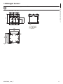
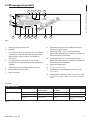
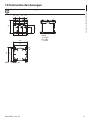
10 Technical drawings
The indicated measurements are expressed in millimetres.
A
A
A
B B
A
C
Fig. 8 MAXIMUS MBX.

MNVCMBX_1929_EN
Headquarters Italy Videotec S.p.A.
Via Friuli, 6 - I-36015 Schio (VI) - Italy
Tel. +39 0445 697411 - Fax +39 0445 697414
Email: [email protected]
France Videotec France SARL
Immeuble Le Montreal, 19bis Avenue du Québec, ZA de Courtaboeuf
91140 Villebon sur Yvette - France
Tel. +33 1 60491816 - Fax +33 1 69284736
Email: info.fr@videotec.com
Asia Pacic Videotec (HK) Ltd
Flat 8, 19/F. On Dak Industrial Building, No. 2-6 Wah Sing Street
Kwai Chung, New Territories - Hong Kong
Tel. +852 2333 0601 - Fax +852 2311 0026
Email: info.hk@videotec.com
Americas Videotec Security, Inc.
Gateway Industrial Park, 35 Gateway Drive, Suite 100
Plattsburgh, NY 12901 - U.S.A.
Tel. +1 518 825 0020 - Fax +1 518 825 0022
Email: info.usa@videotec.com
www.videotec.com
La pagina si sta caricando...
La pagina si sta caricando...
La pagina si sta caricando...
La pagina si sta caricando...
La pagina si sta caricando...
La pagina si sta caricando...
La pagina si sta caricando...
La pagina si sta caricando...
La pagina si sta caricando...
La pagina si sta caricando...
La pagina si sta caricando...
La pagina si sta caricando...
La pagina si sta caricando...
La pagina si sta caricando...
La pagina si sta caricando...
La pagina si sta caricando...
La pagina si sta caricando...
La pagina si sta caricando...
La pagina si sta caricando...
La pagina si sta caricando...
La pagina si sta caricando...
La pagina si sta caricando...
La pagina si sta caricando...
La pagina si sta caricando...
La pagina si sta caricando...
La pagina si sta caricando...
La pagina si sta caricando...
La pagina si sta caricando...
La pagina si sta caricando...
La pagina si sta caricando...
La pagina si sta caricando...
La pagina si sta caricando...
La pagina si sta caricando...
La pagina si sta caricando...
La pagina si sta caricando...
La pagina si sta caricando...
La pagina si sta caricando...
La pagina si sta caricando...
La pagina si sta caricando...
La pagina si sta caricando...
La pagina si sta caricando...
La pagina si sta caricando...
La pagina si sta caricando...
La pagina si sta caricando...
La pagina si sta caricando...
La pagina si sta caricando...
La pagina si sta caricando...
La pagina si sta caricando...
La pagina si sta caricando...
La pagina si sta caricando...
La pagina si sta caricando...
La pagina si sta caricando...
La pagina si sta caricando...
La pagina si sta caricando...
La pagina si sta caricando...
La pagina si sta caricando...
La pagina si sta caricando...
La pagina si sta caricando...
La pagina si sta caricando...
La pagina si sta caricando...
La pagina si sta caricando...
La pagina si sta caricando...
La pagina si sta caricando...
La pagina si sta caricando...
La pagina si sta caricando...
La pagina si sta caricando...
La pagina si sta caricando...
La pagina si sta caricando...
La pagina si sta caricando...
La pagina si sta caricando...
La pagina si sta caricando...
La pagina si sta caricando...
La pagina si sta caricando...
La pagina si sta caricando...
La pagina si sta caricando...
La pagina si sta caricando...
La pagina si sta caricando...
La pagina si sta caricando...
La pagina si sta caricando...
La pagina si sta caricando...
La pagina si sta caricando...
La pagina si sta caricando...
La pagina si sta caricando...
La pagina si sta caricando...
La pagina si sta caricando...
La pagina si sta caricando...
La pagina si sta caricando...
La pagina si sta caricando...
La pagina si sta caricando...
La pagina si sta caricando...
La pagina si sta caricando...
La pagina si sta caricando...
La pagina si sta caricando...
La pagina si sta caricando...
La pagina si sta caricando...
La pagina si sta caricando...
La pagina si sta caricando...
La pagina si sta caricando...
La pagina si sta caricando...
La pagina si sta caricando...
La pagina si sta caricando...
La pagina si sta caricando...
La pagina si sta caricando...
La pagina si sta caricando...
La pagina si sta caricando...
La pagina si sta caricando...
La pagina si sta caricando...
La pagina si sta caricando...
La pagina si sta caricando...
La pagina si sta caricando...
-
 1
1
-
 2
2
-
 3
3
-
 4
4
-
 5
5
-
 6
6
-
 7
7
-
 8
8
-
 9
9
-
 10
10
-
 11
11
-
 12
12
-
 13
13
-
 14
14
-
 15
15
-
 16
16
-
 17
17
-
 18
18
-
 19
19
-
 20
20
-
 21
21
-
 22
22
-
 23
23
-
 24
24
-
 25
25
-
 26
26
-
 27
27
-
 28
28
-
 29
29
-
 30
30
-
 31
31
-
 32
32
-
 33
33
-
 34
34
-
 35
35
-
 36
36
-
 37
37
-
 38
38
-
 39
39
-
 40
40
-
 41
41
-
 42
42
-
 43
43
-
 44
44
-
 45
45
-
 46
46
-
 47
47
-
 48
48
-
 49
49
-
 50
50
-
 51
51
-
 52
52
-
 53
53
-
 54
54
-
 55
55
-
 56
56
-
 57
57
-
 58
58
-
 59
59
-
 60
60
-
 61
61
-
 62
62
-
 63
63
-
 64
64
-
 65
65
-
 66
66
-
 67
67
-
 68
68
-
 69
69
-
 70
70
-
 71
71
-
 72
72
-
 73
73
-
 74
74
-
 75
75
-
 76
76
-
 77
77
-
 78
78
-
 79
79
-
 80
80
-
 81
81
-
 82
82
-
 83
83
-
 84
84
-
 85
85
-
 86
86
-
 87
87
-
 88
88
-
 89
89
-
 90
90
-
 91
91
-
 92
92
-
 93
93
-
 94
94
-
 95
95
-
 96
96
-
 97
97
-
 98
98
-
 99
99
-
 100
100
-
 101
101
-
 102
102
-
 103
103
-
 104
104
-
 105
105
-
 106
106
-
 107
107
-
 108
108
-
 109
109
-
 110
110
-
 111
111
-
 112
112
-
 113
113
-
 114
114
-
 115
115
-
 116
116
-
 117
117
-
 118
118
-
 119
119
-
 120
120
-
 121
121
-
 122
122
-
 123
123
-
 124
124
-
 125
125
-
 126
126
-
 127
127
-
 128
128
-
 129
129
-
 130
130


in altre lingue
- français: Videotec MAXIMUS MBX Manuel utilisateur
- Deutsch: Videotec MAXIMUS MBX Benutzerhandbuch
- português: Videotec MAXIMUS MBX Manual do usuário
Documenti correlati
-
Videotec MAXIMUS MPX SERIES2 Manuale utente
-
Videotec WASEX Manuale utente
-
-
-
-
-
-
-
Videotec EXHC000G Manuale utente
-
Altri documenti
-
SCANGRIP NOVA-EX Manuale del proprietario
-
 Scame electrical solutions OPTIMA-EX Series Installation, Use And Maintenance Manual
-
Crosby SU3593 Manuale utente
-
Honeywell 50047766MICRO SWITCH BX2 Series Explosion-Proof Limit Switch (Stainless Steel) Guida d'installazione
-
Wolf HT-650 Operation And Maintenance Instructions
-
 Stahl IS-TC1A.1 Istruzioni per l'uso
-
 Stahl IS-TH1XX.1 Istruzioni per l'uso
-
-
-


